MQ4WBD512USB 802.11b Wireless LAN Adapter
Abocom Systems Inc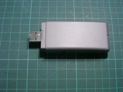
Click to zoom
Application Details
- Equipment Class
- DTS - Digital Transmission System
- Date of Grant
- Nov 20, 2003
- Application Purpose
- Original Equipment
- Date of Application
- Nov 11, 2003
- Equipment Note
- USB 802.11b Wireless LAN Adapter
- Frequency Range
- 2412.00000000 - 2462.00000000
- Company
- Abocom Systems Inc
- Country
- Taiwan
Documents & Files
Document Text
Text extracted from the exhibit documents filed with the FCC. Open a document above to read the original.
Users Manual
Doc. No.: 082203-01 USB 802.11b Wireless LAN Adapter /Flash Disk REGULATORY STATEMENTS FCC Certification The United States Federal Communication Commission (FCC) and the Canadian Department of Communications have established certain rules governing the use of electronic equipment. Part15, Class B This device 802.11b Wireless LAN/Disk (WBD512) and 802.11b Wireless LAN USB Adapter (WUB1600) complies with Part 15 of FCC rules. Operation is subject to the following two conditions: 1) This device may not cause harmful interface, and 2) This device must accept any interface received, including interface that may cause undesired operation. This equipment has been tested and found to comply with the limits for a Class B digital device, pursuant to Part 15 of the FCC Rules. These limits are designed to provide reasonable protection against harmful interference in a residential installation. This equipment generates, uses and can radiate radio frequency energy, and if not installed and used in accordance with the instructions, may cause harmful interference to radio communications. However, there is no guarantee that interference will not occur in a particular installation. If this equipment does cause harmful interference to radio or television reception, which can be determined by turning off and on, the user is encouraged to try to correct the interference by one or more of the following measures: ÿ Reorient or relocate the receiving antenna. ÿ Increase the distance between the equipment and receiver. ÿ Connect the equipment into an outlet on a circuit different from that to which the receiver is connected. Warning: Changes or modifications to this unit not expressly approved by the party responsible for compliance could void the user authority to operate the equipment. Tested To Comply With FCC Standards. FOR HOME OR OFFICE USE. CAUTION: 1) This transmitter must not be co-located or operating in conjunction with any other antenna or transmitter. 2) The equipment complies with FCC RF radiation exposure limits set forth for an uncontrolled environment, under 47 CFR 2.1093 paragraph (d)(2). 3) This Transmitter must not be co-located or operating in conjunction with any other antenna or transmitter The 11Mbps Wireless LAN PCMCIA Card has been tested to the FCC exposure requirements (Specific Absorbtion Rate). U.S. Service Centre: Company name: Xterasys Corporation Address:4711 CHINO AVE. CHINO,CA91710 USA Contact person: Mr. Larry TEL: 909-590-0600 FAX: 909-590-0388 Table of Contents FCC CERTIFICATION................1 INTRODUCTION........................1 PARTS NAME AND FUNCTIONS...............1 LED Indicators.......................1 Switch (optional).....................2 PART 1: 802.11B WIRELESS LAN........1 INSTALLATION...............................2 INSTALL THE DRIVER & UTILITY............2 In Windows 98SE/ME...............2 In Windows 2000.....................5 In Windows XP......................6 INSTALL THE DEVICE.........................8 In Windows 98SE...................8 In Windows ME.....................10 In Windows 2000....................11 In Windows XP......................12 Verify.................................1 6 NETWORK CONNECTION................17 IN WINDOWS 98SE/ME......................17 IN WINDOWS 2000/XP........................21 CONFIGURATION...........................2 5 USE MANUFACTURER’S CONFIGURATION UTILITY.......................................27 Configuration Tool.................28 More Setting........................30 Advanced Setting...................36 Information..........................39 USE WINDOWS XP CONFIGURATION UTILITY........................................4 0 UNINSTALLATION..........................4 9 UNINSTALL THE MANUFACTURER’S CONFIGURATION UTILITY....................49 UNINSTALL THE DEVICE......................50 PART 2: USB FLASH DISK.................1 INSTALL DRIVER............................2 Windows 98/98SE – Install from CD RO.................................2 Windows ME/2000/XP-No Driver is Required............................3 REMOVING YOUR USB FLASH DISK.........4 MANAGE YOUR USB FLASH DISK.....5 MAIN MENU....................................5 DISK MANAGER...............................6 DISK PARTITION...............................6 Switch between Protected and Un-protected Disks..................8 PASSWORD MANAGER........................10 Change Password.....................10 Password Hint........................11 PC LOCK......................................11 Plug-in USB Flash Disk............11 Plug-in USB Flash Disk and Input Password..............................1 2 To lock a PC..........................13 To unlock a PC.......................14 Part 1: 802.11b Wireless LAN 1-1 Introduction About this manual This document is composed of two parts, which will guide you through the installation procedures for setting up the 802.11b Wireless LAN USB Adapter and the optional USB Flash Disk, respectively. However, if you want to use the optional USB Flash Disk function in Windows ME/2000/XP, no driver installation is required since it is Plug and Play ready. Parts name and functions LED Indicators Link/ACT: Green, on/Blink Power: Green, on Part 1: 802.11b Wireless LAN 1-2 Switch (optional) Switch left to use this device as a Wireless LAN adapter, switch right to use it as a Flash Disk. USB Extension Cable to be used together with USB Adapter. The product must be used with the USB cable and a separation distance of at least 20cm must be maintained between the antenna of this device and users. Part 1: 802.11b Wireless LAN 1-3 USB extension cable Part 1: 802.11b Wireless LAN 1-1 Part 1: 802.11b Wireless LAN Part 1: 802.11b Wireless LAN 1-2 Installation Install the Driver & Utility Note: Always remember to install the Driver & Utility before you plug USB cable into the PC’s USB port. In Windows 98SE/ME For Windows 98SE users: As you perform the installation, have your system operating CD-ROM at hand. You may be asked to insert the…
Text truncated - open the document above for the full version.
Cover Letter(s)
Company AboCom Systems, Inc. Address 1F, No. 21, R&D Rd. II, SBIP, Hsin-Chu 300, Taiwan Country Taiwan Telephone number 03-5789090 Fax number 03-589520 Internet www.abocom.com.tw Federal Communications Commission Authorization and Evaluation Division Confidentiality Request RE: FCC ID: MQ4WBD512 Pursuant to Sections 0.457 and 0.459 of the Commission’s Rules, the Applicant hereby requests confidential treatment of information accompanying this Application as outlined below: Schematics.pdf Block Diagram.pdf Operational Descriptions.pdf The above materials contain trade secrets and proprietary information not customarily release to the public. The public disclosure of these matters might be harmful to the Applicant and Provide unjustified benefits to its competitors. The Applicant understands that pursuant to Rule 0.457, disclosure of this Application and all accompanying documentation will not be made before the data of the Grant for this application. Sincerely, Iris Huang Printed Name Position Company name AboCom Systems, Inc. Head Office: 1F, No. 21, R&D Rd. II, SBIP, Hsin-Chu 300, Taiwan, R.O.C. Factory: No. 77, Yu-Yih Rd., Chu-Nan Chen, Miao-Lih Hsian 350, Taiwan, R.O.C. Mobile Interconnected Products: 8F, No. 123, Lane 235, Bao-Chiao Rd, Hsin-Tien City, Taipei 231, Taiwan, R.O.C. TEL: +886-37-580-777 FAX: +886-37-580-799 http://www.abocom.com
Cover Letter(s)
American Telecommunications Certification Body Inc. 6731 Whittier Ave, McLean, VA 22101 September 24, 2003 RE: AboCom System, Inc. FCC ID: MQ4WBD512 After a review of the submitted information, I have a few comments on the above referenced Application. 1) The maximum EIRP of the device is about 153.1 mW - 1.88 dBi = 99.3 mW. The FCC is expected to require any 2.4835 GHz band USB dongle to require SAR evaluation if the device exceeds 24.5 mW (conducted OR EIRP power). Simply providing the user with a cable and instructions is not considered significant enough to quantify this device as mobile. Because this device contains a standard USB connector and may be directly connected to a laptop by the user, the options available include one of the following: a) Perform the necessary SAR testing, or b) reduce the power such that both the conduced and EIRP power are less than 24.5 mW, or c) Change the connector from a standard USB connector (Type A) to a Type B, or some other nonstandard connector and provide the required extension cable. Because the connector is non- standard they will be forced to use the cable and the device may be considered as mobile in this case, or d) provide the product with a permanent built in cord so that the user is required to use the cord and an ensure the 20 cm spacing requirements. This configuration may be considered mobile. e) Note: The FCC's perspective is if users can operate a device in such configurations or conditions because of the way a device is designed or manufactured, these configurations should also be evaluated to ensure compliance. This is why the FCC considers these devices to be able to be used < 2.5 cm. 2) The RF exposure information given in the manual will change due to item 1 above. 3) The 6 dB bandwidth is incorrectly measured. The markers should be placed on the outer most 6 dB points. This will typically yield a results close to 10 MHz. Please provide corrected measurements. 4) Please explain the difference between the Reading column in dBm and the output power in dBm column shown in the power measurements portion of the report. 5) Page 19 of 39 of the test report contains an additional column "Average Factor" with large values. Please explain. Additionally much of the data in this table does not make sense. 6) Given an output power of 153 mw and antenna gain of -1.88 dBi, the power measured in the bandedge plots appears about 10-15 dB lower than expected. Note that this factor already includes an expected 10 dB difference due to the wideband nature of the signal. Far Field calculations yield about 113 dBuV/m - 10 dB difference = approximately 103 dBuV/m. Please explain. Timothy R. Johnson Examining Engineer mailto: [email protected] The items indicated above must be submitted before processing can continue on the above referenced application. Failure to provide the requested information may result in application termination. Correspondence should be considered part of the permanent submission and may be viewed from the Internet after a Grant of Equipment Authorization is issued. Please do not respond to this correspondence using the email reply button. In order for your response to be processed expeditiously, you must submit your documents through the AmericanTCB.com website. Also, please note that partial responses increase processing time and should not be submitted. l Page 2September 24, 2003 Any questions about the content of this correspondence should be directed to the sender.
Cover Letter(s)
American Telecommunications Certification Body Inc. 6731 Whittier Ave, McLean, VA 22101 October 25, 2003 RE: AboCom System, Inc. FCC ID: MQ4WBD512 After a review of the submitted information, I have a few comments on the above referenced Application. 1) This device comes in 4 models with different memory sizes and also one model without the Memory Disk. Note that due to the close proximity of all components and the differences are metallic in nature, each model should have been investigated by testing in order to determine the worse case. Note that the worse case can not simply be assumed. If the different size memories use are actually the exact same layout, only a different component, you may be able to justify these to be the same in nature. However the version without the memory disk should have been pretested and compared to the sample tested in order to determine worse case. Please comment. 2) Please comment on the Probe Angle between the probe axis and surface normal line. Was this maintained at < 30 degrees. Note that if the probe angle is > 30 degrees and the closest point of the probe tip housing to the phantom surface is closer than a probe diameter, the boundary effect may become large and polarization dependent. This additional uncertainty needs to be analyzed and taken into account. Was this done? 3) A zoom scan plot should be provided for the worse case results. 4) Please comment of if the scan procedures given on page 15 for the system validation also apply to the general scan procedures for the test scans. 5) The test report does not appear to provide a description of the validation dipole used, other than including the calibration certificate. Please add this information to the report. 6) The test report should contain the composition, ingredients, and amounts for tissue liquid listed. 7) The 2450 MHz dipole calibration is listed in the report as N/A. The FCC usually desires this to be calibrated since it is the reference for you verification. They also ask that the most recent manufacturer/calibration reference dipole data is included. Please provide and/or comment. 8) The FCC desires that return loss data for the dipole used for verification be provided for the report. This is typically included as part of the manufacturer calibration. Please provide. 9) Please comment on if boundary effect compensation was used. Note that when Probe boundary effect compensation is not used the probe tip should be positioned at least half a probe tip diameter from the phantom surface during area and zoom scans. Please comment. 10) Please comment on if the first 2 measurements points in a direction perpendicular to the surface of the phantom during the zoom scan and closest to the phantom surface, were within 1 cm of the surface. --- Continued on Next Page --- z Page 2October 25, 2003 11) Your previous response to the following question: Given an output power of 153 mw and antenna gain of -1.88 dBi, the power measured in the bandedge plots appears about 10-15 dB lower than expected. Note that this factor already includes an expected 10 dB difference due to the wideband nature of the signal. Far Field calculations yield about 113 dBuV/m - 10 dB difference = approximately 103 dBuV/m. Please explain. Stated "This is because we add 10dB external attenuator". Note that if 10 dB attenuation was added, then the limit line would also need to be adjusted by 10 dB to compensate. However, given that the limit of 74 and 54 dBuV/m are shown at 74 and 54 dBuV/m, these plots were assumed to be corrected for factors such as preamp, cables, antennas, and attenuators. If all factors have been considered, then the level appears lower than expected as given above. Please provide further explanation. Timothy R. Johnson Examining Engineer mailto: [email protected] The items indicated above must be submitted before processing can continue on the above referenced application. Failure to provide the requested information may result in application termination. Correspondence should be considered part of the permanent submission and may be viewed from the Internet after a Grant of Equipment Authorization is issued. Please do not respond to this correspondence using the email reply button. In order for your response to be processed expeditiously, you must submit your documents through the AmericanTCB.com website. Also, please note that partial responses increase processing time and should not be submitted. Any questions about the content of this correspondence should be directed to the sender.
Cover Letter(s)
American Telecommunications Certification Body Inc. 6731 Whittier Ave, McLean, VA 22101 November 12, 2003 RE: AboCom System, Inc. FCC ID: MQ4WBD512 After a review of the submitted information, I have a few comments on the above referenced Application. 1) It appears that the difference between the WUB1600 & WBD512 is that the daughter board is present in only one version. Please comment. Because of the fact that SAR is not necessarily based on power alone, but that nearby metallic objects affect SAR results due to variances in coupling and surface currents, both of these models should have at least been pretested for SAR in order to determine worse case. Justification on conducted power measurements alone is not sufficient. 2) Additionally, careful examination of the test photographs, internal photographs, and external photographs for SAR suggests that the configuration with the bottom side of the laptop facing positions the device such that the antenna is on the opposite side of the device from the phantom. Due to variances in laptops, etc, The side with the antenna should have been positioned against the phantom. Additional data should be taken. Timothy R. Johnson Examining Engineer mailto: [email protected] The items indicated above must be submitted before processing can continue on the above referenced application. Failure to provide the requested information may result in application termination. Correspondence should be considered part of the permanent submission and may be viewed from the Internet after a Grant of Equipment Authorization is issued. Please do not respond to this correspondence using the email reply button. In order for your response to be processed expeditiously, you must submit your documents through the AmericanTCB.com website. Also, please note that partial responses increase processing time and should not be submitted. Antenna Appears to be Here z Page 2November 12, 2003 Any questions about the content of this correspondence should be directed to the sender.
Cover Letter(s)
Dear Timothy, Thanks for your information. We have modified the report as per your review comments and have the file attached for your review. Please see the explanation below: 1) We conducted the SAR test per your requirement. Please find the SAR report as file attached for your review. 2) We modified the user"s manual as per your requirement and have it attached for your reference. 3) About 6 dB bandwidth was incorrectly measured: we remeasured and modified it in section 3 in FCC report. Please find the FCC report as file attached for your review. 4) About difference between the Reading column in dBm and the output power in dBm column: we modified it in section 4 (page 12 of 38) of FCC report as file attached for your review. 5) Page 19 of 38 of the test report contains an additional colume "Average Factor: We have modified it (in page 19 of 38). Please also find the revised FCC report for your review. 6) About quesiotn 6, that's because we add 10dB external attenuator. I hope the supplementary statisfy all your requirement for reviewing this application. If you have further question, please feel free to let me know. Best Regards Sunny Liu To: [email protected] Subject: Re: Review of AboCom System, Inc., FCC ID: MQ4WBD512 10/23/2003file://C:\DOCUME~1\TIMOTH~1.JOH\LOCALS~1\Temp\eud231.htm
Cover Letter(s)
Dear Timothy, Sorry for the late response. We have modified the report as per your review comments, please see the explanation below: For question 1, 3, 5, 6, 7 and 8 We have modified the report per your comments. Please find the SAR Report as the file that we upload to the website for your review. For question 2, 9 and 10 The questions concerned have been asked by FCC and explained to FCC by the system provider, IndexSar. Please see the explanation from IndexSAR. For question 4 Yes, the test scan procedure for system validation also apply to the general scan procedure except for the set-up position. For general scan, the EUT was placed at the side of phantom. For validation scan, the dipole antenna was placed at the bottom of phantom. For question 11 We remeasured the band-edge test and modified it to FCC ID report. Please see the band-edge plot as file that we upload to the website for your review. I hope the supplementary satisfy your requirement for reviewing this application. If you have further question, please feel free to let me know. Best Regards, Julia Chu -----Original Message----- From: Timothy R. Johnson [mailto:[email protected] ] Sent: Sunday, October 26, 2003 8:12 AM To: [email protected]; [email protected] Cc: [email protected]; [email protected]; [email protected] Subject: Review of AboCom System, Inc., FCC ID: MQ4WBD512 after recent uploads To: [email protected] Subject: FW: Review of AboCom System, Inc., FCC ID: MQ4WBD512 after recent uploads 11/12/2003file://C:\DOCUME~1\TIMOTH~1.JOH\LOCALS~1\Temp\eud2F7.htm Elton/Julia/Sunny, Attached are comments regarding review of this application. Thank You, Timothy R. Johnson, NARTE Certified EMC Engineer (No. EMC-002205-NE) Examining Engineer American TCB, Inc. 6731 Whittier Ave. McLean, VA 22101 email: [email protected] alternate email: [email protected] direct number: 404-414-8071 corporate phone: 703-847-4700 corporate fax: 703-847-6888 << File: explanation from IndexSAR.doc >> << File: 031156 (FCC SAR, WBD512)-new.rar >> Your Global Partners in Quality ________________________________________________________________ Confidentiality Notice: All information or opinions expressed in this message and/or any attachments are those of the author and are not necessarily those of Intertek Testing Services or its associated companies. Intertek Testing Services accepts no responsibility for loss or damage arising from its use, including damage from virus. Any personal data contained in this e-mail is treated with the strictest confidence. If you have received this message in error, please notify us immediately and delete it from your system. Our privacy policy can be found at http://www.intertek -labtest.com/home/privacy.htm Please note that any direct business correspondence contained in this e-mail is subject to our business Terms & Conditions available upon request from the sender. 11/12/2003file://C:\DOCUME~1\TIMOTH~1.JOH\LOCALS~1\Temp\eud2F7.htm
Cover Letter(s)
Dear Timothy, As per your comments, we have modified the SAR report and just uploaded to ATCB website for your review. Since this project has spent some time in modify and test for this SAR report, if the report is ok after your review, would you please issue the Grant in the short time? Many thanks for your kindly help. If you have further question, please feel free to let me know. Thanks and Best Regards, Julia Chu To: [email protected] Subject: RE: Review of AboCom System, Inc., FCC ID: MQ4WBD512 after recent uploads Page 1 of 1AboCom MQ4WBD512 11/21/2003Printed for "Timothy R. Johnson" <[email protected]>
External Photos
Photo 1: Exterior photo WBD512 Photo 2: Exterior photo WBD512 Photo 3: Exterior photo WBD512 Photo 4: Exterior photo WBD512
ID Label/Location Info
FCC ID Label Location 71.3 mm 32.6 mm
RF Exposure Info
0597 ILAC MRA Specific Absorption Rate (SAR) Test Report for AboCom System, Inc. on the 802.11b Wireless LAN/Disk Model Number: WBD512 Test Report: EME-031156 Date of Report: Oct. 17, 2003 Date of test: Oct. 16, 2003 Total No of Pages Contained in this Report: 83 Accredited for testing to FCC Part 15 Tested by: Kevin Chen Reviewed by: Elton Chen Review Date: Oct. 17, 2003 All services undertaken are subject to the following general policy: Reports are submitted for exclusive use of the client to whom they are addressed. Their significance is subject to the adequacy and representative character of the samples and to the comprehensiveness of the tests, examinations or surveys made. This report shall not be reproduced except in full, without written consent of Intertek Testing Services, Taiwan Ltd. FCC ID. : MQ4WBD512 Report No.: EME-031156 Page 2 of 83 Table of Contents STATEMENT OF COMPLIANCE...............................................................................3 1.0 Job Description...........................................................................................................4 1.1 Client Information...................................................................................................4 1.2 Equipment under test (EUT)...................................................................................4 Portable..............................................................................................................................4 1.3 Test plan reference..................................................................................................5 1.4 System test configuration........................................................................................5 1.4.1 System block diagram & Support equipment......................................................5 1.4.2 Test Position.........................................................................................................6 1.4.3 Test Condition......................................................................................................6 1.5 Modifications required for compliance...................................................................8 1.6 Additions, deviations and exclusions from standards.............................................8 2.0 SAR Evaluation..........................................................................................................9 2.1 SAR Limits.............................................................................................................9 2.2 Configuration Photographs...................................................................................10 2.3 SAR measurement system....................................................................................18 2.4 SAR measurement system validation...................................................................19 2.5 Test Result.............................................................................................................20 3.0 Test Equipment.........................................................................................................23 3.1 Equipment List......................................................................................................23 3.2 Body Tissue Simulating Liquid for evaluation test...............................................24 3.3 Head Tissue Simulating Liquid for System performance Check test...................25 3.4 E-Field Probe and 2450MHz Balanced Dipole Antenna Calibration...................25 3.5 Measurement Uncertainty.....................................................................................26 3.6 Measurement Traceability.....................................................................................27 4.0 WARNING LABEL INFORMATION - USA..........................................................28 5.0 REFERENCES.........................................................................................................29 6.0 DOCUMENT HISTORY..........................................................................................30 APPENDIX A - SAR Evaluation Data...........................................................................31 APPENDIX B – 2450MHz body liquid Calibration Data..............................................49 APPENDIX C - E-Field Probe and 2450MHz Balanced dipole antenna Certificate and Calibration Data..............................................................................................................56 FCC ID. : MQ4WBD512 Report No.: EME-031156 Page 3 of 83 STATEMENT OF COMPLIANCE The AboCom sample device, model # WBD512 was evaluated in accordance with the requirements for compliance testing defined in FCC OET Bulletin 65, Supplement C (Edition 01-01). Testing was performed at the Intertek Testing Services facility in Hsinchu, Taiwan. For the evaluation, the dosimetric assessment system INDEXSAR SARA2 was used. The phantom employed was the box phantom of 2mm thick in one wall. The total uncertainty for the evaluation of the spatial peak SAR values averaged over a cube of 1g tissue mass had been assessed for this system to be ±29.7%. The device was tested at their maximum output power declared by the AboCom. In summary, the maximum spatial peak SAR value for the sample device averaged over 1g was found to be: Phantom Position SAR 1g , mW/g 2mm thick box phantom wall EUT bottom to the phantom, 0 mm separation. 0.364 mW/g. In conclusion, the tested Sample device was found to be in compliance with the requirements defined in OET Bulletin 65, Supplement C (Edition 01-01) for body configurations. FCC ID. : MQ4WBD512 Report No.: EME-031156 Page 4 of 83 1.0 Job Description 1.1 Client Information The WBD512 has been tested at the request of: Company: AboCom System, Inc. 300 1F, No. 21, R&D Rd. II, SBIP, Hsin-Chu, Taiwan 1.2 Equipment under test (EUT) Product Descriptions: Equipment 802.11b Wireless LAN/Disk Trade Name AboCom Model No: WBD512 FCC ID MQ4WBD512 S/N No. Not…
Text truncated - open the document above for the full version.
RF Exposure Info
Suggested responses to ATCB questions on MQ4WBD512 Question 2: There are many benefits in terms of usability and reduced uncertainty in using upright phantoms compared to horizontal bath phantoms. Since the angle to the source direction can be greater than 30 degrees, the uncertainty allowances for SARA2 systems include allowance for the whole spherical isotropy range of the probes rather than just an allowance for rotational isotropy about the probe axis. The additional uncertainty allowance can be more than offset by the uncertainty reductions with an upright geometry. These include: 1. Lower phone positioning uncertainty 2. Reduced effects from liquid evaporation 3. Reduced influence of stratification of liquid properties at measurement depth In response to FCC requests, Indexsar have performed specific tests to demonstrate that tests at the side of the phantom give equivalent results to tests at the bottom of a bath (probe angled or end-on). These have been reported in several Reports submitted to FCC: 1. IXS0209 (April 2002) Error assessment for probe/interface proximity effects for an upright phantom 2. IXS0214 (September 2002) Error assessment for probe/interface proximity effects for an upright phantom geometry at 1800MHz 3. ISX0215 (October 2002) SARA2 validation testing with CDMA-modulated signals at bottom and side of phantom at 1900MHz These reports showed that probe sensitivity is the same when the f…
Text truncated - open the document above for the full version.
Contact Information
Applicant
Harry Huang(Manager)
Technical Contact
Intertek Testing Services Taiwan Ltd.Elton Chen
[email protected](+886)-3-519-1411
No. 11, Ko-Tze-Nan Chia-Tung Li · Hsinchu · Taiwan
Non-Technical Contact
Intertek Testing Services Taiwan Ltd.Elton Chen
[email protected](+886)-3-519-1411
Test Firm
Intertek Testing Services Taiwan Ltd.Alpha Liu
Technical Specifications
| # | Rule Parts | Frequency Range | Power Output |
|---|---|---|---|
| 1 | 15C | 2.41 GHz - 2.46 GHz | 84.00 mW |
Other Applications from Abocom Systems Inc

MQ4WM5208
Oct 27, 2015802.11b/g/n Module
Equipment Class
DTS - Digital Transmission System
MQ4AM7221
Mar 18, 20152T2R 802.11b/g/n/ac Module
Equipment Class
DTS - Digital Transmission System
MQ4PLW72
Mar 18, 201511ac WiFi Extender Smart Plug / 11ac WiFi Extender
Equipment Class
NII - Unlicensed National Information Infrastructure TX
MQ4CB1522M
Sep 22, 2014IP Camera
Equipment Class
DTS - Digital Transmission System
MQ4-MBR-1100
Sep 21, 2014Android TV Dongle
Equipment Class
JBC - Part 15 Class B Computing Device/Personal Computer