MQ4WMG2400802.11b/g Wirless LAN mini PCI Card
Abocom Systems Inc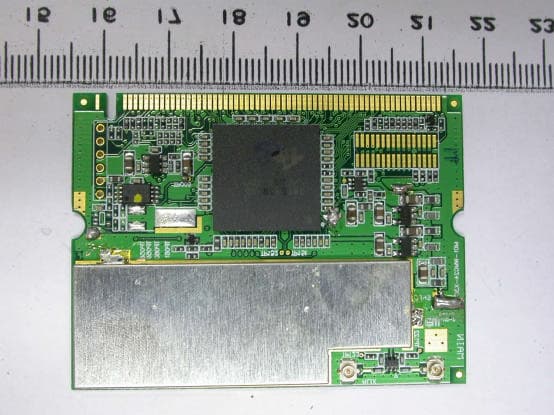
Click to zoom
Application Details
- Equipment Class
- DTS - Digital Transmission System
- Date of Grant
- Jun 25, 2004
- Application Purpose
- Original Equipment
- Date of Application
- Jun 25, 2004
- Equipment Note
- 802.11b/g Wirless LAN mini PCI Card
- Frequency Range
- 2412.00000000 - 2462.00000000
- Company
- Abocom Systems Inc
- Country
- Taiwan
Documents & Files
Document Text
Text extracted from the exhibit documents filed with the FCC. Open a document above to read the original.
Users Manual
Doc. No.:120903-01 802.11g Wireless LAN Card User’s Manual REGULATORY STATEMENTS FCC Certification The United States Federal Communication Commission (FCC) and the Canadian Department of Communications have established certain rules governing the use of electronic equipment. Part15, Class B Warning: Changes or modifications to this unit not expressly approved by the party responsible for compliance could void the user authority to operate the equipment. This device complies with Part 15 of FCC rules. Operation is subject to the following two conditions: 1) This device may not cause harmful interface, and 2) This device mu12st accept any interface received, including interface that may cause undesired operation. This equipment has been tested and found to comply with the limits for a Class B digital device, pursuant to Part 15 of the FCC Rules. These limits are designed to provide reasonable protection against harmful interference in a residential installation. This equipment generates uses and can radiate radio frequency energy, and if not installed and used in accordance with the instructions, may cause harmful interference to radio communications. However, there is no guarantee that interference will not occur in a particular installation. If this equipment does cause harmful interference to radioor television reception, which can be determined by turning off and on, the user is encouraged to try to correct the interference by one or more of the following measures: Reorient or relocate the receiving antenna. Increase the distance between the equipment and receiver. Connect the equipment into an outlet on a circuit different from that to which the receiver is needed. Consult the dealer or an experienced radio/TV technician for help. Channel The Wireless Channel sets the radio frequency used for communication. Access Points use a fixed Channel. You can select the Channel used. This allows you to choose a Channel which provides the least interference and best performance. In the USA and Canada, 11 channel are available. If using multiple Access Points, it is better if adjacent Access Points use different Channels to reduce interference. In "Infrastructure" mode, Wireless Stations normally scan all Channels, looking for an Access Point. If more than one Access Point can be used, the one with the strongest signal is used. (This can only happen within an ESS.) If using "Ad-hoc" mode (no Access Point), all Wireless stations should be set to use the same Channel. However, most Wireless stations will still scan all Channels to see if there is an existing "Ad-hoc" group they can join. CAUTION: 1) To comply with FCC RF exposure compliance requirements, a separation distance of at least 20 cm must be maintained between the antenna of this device and all persons. 2) This transmitter must not be co-located or operating in conjunction with any other antenna or transmitter. This device is intended only for OEM integrators under the following conditions: 1) The antenna must be installed such that 20 cm is maintained between the antenna and users. For laptop installations, the antenna must be installed to ensure that the proper spacing is maintained in the event the users places the device in their lap during use (i.e. positioning of antennas must be placed in the upper portion of the LCD panel only to ensure 20 cm will be maintained if the user places the device in their lap for use) and 2) The transmitter module may not be co-located with any other transmitter or antenna. As long as the 2 conditions above are met, further transmitter testing will not be required. However, the OEM integrator is still responsible for testing their end-product for any additional compliance requirements required with this module installed (for example, digital device emissions, PC peripheral requirements, etc.). IMPORTANT NOTE: In the event that these conditions can not be met (for example certain laptop configurations or co-location with another transmitter), then the FCC authorization is no longer considered valid and the FCC ID can not be used on the final product. In these circumstances, the OEM integrator will be responsible for re-evaluating the end product (including the transmitter) and obtaining a separate FCC authorization. End Product Labeling This transmitter module is authorized only for use in devices where the antenna may be installed such that 20 cm may be maintained between the antenna and users (for example access points, routers, wireless ASDL modems, certain laptop configurations, and similar equipment). The final end product must be labeled in a visible area with the following: "Contains TX FCC ID: MQ4WMG2400". RF Exposure Manual Information That Must be Included The users manual for end users must include the following information in a prominent location "IMPORTANT NOTE: To comply with FCC RF exposure compliance requirements, the antenna used for this transmitter must be installed to provide a separation distance of at least 20 cm from all persons and must not be co-located or operating in conjunction with any other antenna or transmitter Additional Information That Must be Provided to OEM Integrators This device can only installed on the PCI card by the OEM or the OEM integrator. Installation instructions are not allowed to be provided to the end user. Table of Contents INTRODUCTION...................................................................................... 1 WIRELESS NETWORK OPTIONS................................................................. 1 The Peer-to-Peer Network............................................................ 1 The Access Point Network........................................................... 2 LED INDICATORS FOR WIRELESS CARDBUS CARD.................................. 2 Power Indicator: (Orange LED)................................................... 2 Act Indicator: (Green LED)......................................................... 3 INSTALLATION.................…
Text truncated - open the document above for the full version.
Users Manual
All the antennas tested for WMG2400 will not be used in the notebook computer or laptop but the antennas will be installed in the desktop computer with PCI extended adapter. (Please see the figures). The notebook computer manufacturers have their own antennas to fit their design. If we ship WMG2400 to the notebook computer manufacturer, we will apply another FCC test with another antenna. The three antennas will be installed in PCI extended card and wireless router. (or wireless access point. Please see the figures) OEM Installation Manual NOTE:This divice can only be installedo on the PCI card by the OEM or the OEM integrator. It's can't be installed by end user. FCC ID: MQ4WMG2400
Users Manual
All the antennas tested for WMG2400 will not be used in the notebook computer or laptop but the antennas will be installed in the desktop computer with PCI extended adapter. (Please see the figures). The notebook computer manufacturers have their own antennas to fit their design. If we ship WMG2400 to the notebook computer manufacturer, we will apply another FCC test with another antenna. The three antennas will be installed in PCI extended card and wireless router. (or wireless access point. Please see the figures)
Cover Letter(s)
AboCom Systems, Inc. Head Office: 1F, No. 21, R&D Rd. II, SBIP, Hsin-Chu 300, Taiwan, R.O.C. Factory: No. 77, Yu-Yih Rd., Chu-Nan Chen, Miao-Lih Hsian 350, Taiwan, R.O.C. Mobile Interconnected Products: 8F, No. 123, Lane 235, Bao-Chiao Rd, Hsin-Tien City, Taipei 231, Taiwan, R.O.C. TEL: +886-37-580-777 FAX: +886-37-580-799 http://www.abocom.com Request for modular approval – FCC ID: MQ4WMG2400 Dear Application Examiner, The AboCom Product Development The 802.11b/g Wireless LAN MiniPCI Card WMG2400 is seeking FCC authorization as a module transmitter. The requirements of the FCC Public notice DA00-1407 are met. The following requirements are fulfilled: 1. The module transmitter must have its own shielding The radio portion of the module is contained in its own RF shielding. See the external photos. 2. The modular transmitter must have buffered modulation /data inputs The module has a memory management unit inside of the IC. It buffers the data inputs from UART and Mini PCI terminal. 3. The modular transmitter must have its own power supply regulation The IC contains an own voltage regulation. In case of change in the supply voltage VCCfor example cause by temperature changes or other effect,the internal voltage will be stabilized. 4. The modular transmitter must comply with the antenna requirement of Section 15.203 and 15.204c The transmitter shall only be used with the tested integral antenna or with an antenna that has less antenna gain. Requirement for the use of external antennas are specified in the antenna information exhibit.See Dipole Antenna SJW-0007ASMA Antenna C068-510195-AW111-094-D8 5. The modular transmitter must be tested in a stand-alone configuration The EUT was tested in a stand-alone configuration. The module was fixed in test/programming board during the test. See also the test report and Test setup photos. AboCom Systems, Inc. Head Office: 1F, No. 21, R&D Rd. II, SBIP, Hsin-Chu 300, Taiwan, R.O.C. Factory: No. 77, Yu-Yih Rd., Chu-Nan Chen, Miao-Lih Hsian 350, Taiwan, R.O.C. Mobile Interconnected Products: 8F, No. 123, Lane 235, Bao-Chiao Rd, Hsin-Tien City, Taipei 231, Taiwan, R.O.C. TEL: +886-37-580-777 FAX: +886-37-580-799 http://www.abocom.com 6. The modular transmitter must be labeled with its own FCC ID number The EUT will be labeled with its own FCC ID number. If the module is installed inside of an end-product, the label will not be visible. 7. The modular transmitter must comply with any rule or operating requirement applicable to the transmitter and the manufacturer must provide adequate instruction along with the module to explain any such requirements. The EUT is compliant with all applicable FCC rules. Detail instructions are given in the Users Guide. 8. The modular transmitter must comply with any applicable RF exposure requirements. The transmitter herein was tested with the antenna that is integrated on the radio module. Compliance to RF exposure requirements for this antenna is included within this application for approval. Appropriate warning statement will be placed with each end product user information based on the results of the RF exposure data filed with this application. OEM Resellers will be advised to include a similar statement to inform the users of any requirements for RF safety. Please contact us if you have any addition questions. Best Regards, Iris Huang Abocom Systems, Inc. 1F, No.21, R&D Rd. II, SBIP Hsin-Chu, 300 Taiwan, R.O.C. Tel+886-3-578-9090 Fax+886-3-578-9520
Operational Description
WMG2400 A2 CIRCUIT DESCRIPTION HOST MAC BASE BAND TNETW1130 RADIO ANTENNA RF SWITCH CONTROL MAC (Media Access Control) Unit with Baseband Process Unit (U1) The TNETW1130 MAC implements the IEEE Std 802.11 MAC sublayer using both dedicated hardware and embedded firmware. The MAC hardware implements real-time functions, including access protocol management, encryption, decryption, and direct memory access (DMA) transferring of data between the baseband processor and the host. The eCPU runs firmware that manages the flow of commands and data to/from the host, performs scan-and-join operations, and maintains TX and RX queues, as well as a WEP key table stored in internal RAM. The eCPU can override many of the MAC functions that are performed automatically by hardware during normal operation. The baseband processor includes two primary interfaces: radio and MAC. The radio interface provides analog differential signals for transmitting and receiving data by means of 2.4-GHz or 5-GHz radios. The radio interface also includes programmable RX AGC, TX power control, and antenna diversity. The MAC interface ensures that decoded and descrambled RX data is transferred to the MAC for further processing. The MAC interface also allows the MAC to transfer MAC protocol data units (MPDUs) to the baseband processor for encoding and transmission. The baseband processor provides a serial interface through which the MAC accesses registers within the baseband processor core. The baseband processor also provides CCA information to the MAC. RC2422B RF Transceiver Dual-Mode 802.11b/g IQ/IF Transceiver with Dual VCO Synthesizers(U8) The RC2422 is a fully integrated IQ transceiver specifically for use in 802.11 b/g applications. The RC2422 is designed to perform the IQ conversion at 374MHz IF as well as provide an RFLO and control logic to the RFFE (Radio Frequency Front End). The RC2422 also has an internal IQ DC offset calibration function for the receive IQ interface. Combined with the Radia integrated RFFE, the RC2422 completes the Radia WLAN two-chip radio. The RC2422 incorporates all of the system blocks from the modem to the RFFE except for the IF filtering and the reference crystal. The ASIC uniquely incorporates an internal PLL reference oscillator where only a crystal is needed, and also provides a clock output for base-band/MAC ASICs. RC2422 includes two synthesizers with VCOs, IQ modulator, IQ demodulator, anti aliasing filters, IF amplifiers, receive AGC circuit, transmit power control and serial interface. RC2326 Dual-Mode 802.11b/g RFFE ISM band(U2) The RC2321 is a fully integrated Dual Mode Radio Frequency Front End (RFFE) designed specifically for use in 802.11 b/g applications. The RC2321 is designed to perform RF up and down conversions in the unlicensed ISM band. Combined with the Radia RC2422 IF/IQ Tranceiver/Synthesizer, The RC2326 completes the Radia WLAN two-chip radio. The RC2321 incorporates all of the RF blocks for both the “b/g” band except for low cost ceramic filters. The ASIC includes the LNA, PA, mixer, bias circuitry, RX gain control, transmit coupler detector, and T/R switches. High integration and internal RF matching enhances performance and greatly reduce external part count. The only external needed for operation are RF filters and external low power DC switching FETs. Power Regulator(U5,U10,U15) D3.3V Mini PCI Connector D3.3V A3.3V A2.85V A1.5V D1.5V A1.8V LDO Regulator(U5) Filter Transistor Dropout LDO Regulator(U15) LDO Regulator(U10) Digital supply for the TNETW1130 I/O Analog supply for Radio components Analog supply for the TNETW1130 Analog supply for the TNETW1130 Analog supply for the TNETW1130 Digital supply for the TNETW1130 core 802.11 Subsystem Supplies
Operational Description
SPECIFICATION FOR APPROVAL CUSTOMER DATE DESCRIPTION CUSTOMER P/N WANSHIH ELECTRONIC CO., LTD. 723 3F 72 WU KONG 6TH RD., WU KU INDUSTRIAL DISTRICT TAIPEI HSIEN, TAIWAN,R.O.C. TEL(02) 22988066 (5 LINE) FAX(02)22981102 SWIVEL TYPE5dBi DIPOLE ANTENNA REVERSE SMA CONNECTOR 91 12 20 Table of Contents Table of Contents.......................... 1 Specification................................ 2 Drawing..................................... 3 Return Loss ................................. 4 V.S.W.R...................................... 4 Radiation Pattern H Plane Radiation Pattern..............5 E Plane Radiation Pattern..............6 1 SPECIFICATION 1. DESCRITION 2.4Ghz Swivel TypeDipole Antenna 2. CUSTOMER 3. MODEL NO. SJW-0007A 4. APPEARANCE See fig.1 5. FREQUENCY 2.4~2.5Ghz 6. IMPEDANCE 50 Ohm nominal 7. S.W.R. Less than 2.0:1 8. GAIN 5dBi 9. ADMITTED POWER RADIATION 1W 10. TYPE OF RADITION. Toroidal 11. POLARIZATION Vertical 12. ELECTRICAL LENGTH Dipole 13. CONNECTOR SMA reverse connector 14. OPERATION TEMPERATURE RANGE-20~+65 15. STORAGE TEMPERATURE -30~+75 2 3 4 5 6
RF Exposure Info
1.1. Test Result of RF Exposure Evaluation . Product: Wireless Mini PCI Module . Test Item: Test Result of RF Exposure Evaluation . Test site: OATSI-SD . Test Mode: Normal Operation 1.1.1. Antenna Gain Antenna 1 Gain: The maximum Gain is 1.8dBi. Antenna 2 Gain: The maximum Gain is 5.0dBi. Antenna 3 Gain: The maximum Gain is 0 dBi 1.1.2. EUT Operation condition Software provided by client enabled the EUT to transmit and receive data at lowest, middle and highest channel individually. 1.1.3. Output Power into Antenna & RF Exposure Evaluation Distance Antenna 1, Modulation Standard: IEEE 802.11b Test Date: Apr. 24, 2004 Temperature: 24 Humidity: 61 Channel Channel Frequency (MHz) Output Power to Antenna (dBm) Power Density (S) (mW/cm 2 ) 01 2412 15.15 0.0099 06 2437 14.43 0.0084 11 2462 13.55 0.0068 Modulation Standard: IEEE 802.11g Test Date: Apr. 24, 2004 Temperature: 24 Humidity: 61 Channel Channel Frequency (MHz) Output Power to Antenna (dBm) Power Density (S) (mW/cm 2 ) 01 2412 12.23 0.0050 06 2437 11.48 0.0042 11 2462 10.48 0.0034 The MPE is calculated as 0.0099 mW / cm 2 < limit 1 mW / cm 2 . So, RF exposure limit warning or SAR test are not required. Antenna 2, Modulation Standard: IEEE 802.11b Test Date: Apr. 24, 2004 Temperature: 24 Humidity: 61 Channel Channel Frequency (MHz) Output Power to Antenna (dBm) Power Density (S) (mW/cm 2 ) 01 2412 15.15 0.0206 06 2437 14.43 0.0175 11 2462 13.55 0.0142 Modulation Standard: IEEE 802.11g Test Date: Apr. 24, 2004 Temperature: 24 Humidity: 61 Channel Channel Frequency (MHz) Output Power to Antenna (dBm) Power Density (S) (mW/cm 2 ) 01 2412 12.23 0.0105 06 2437 11.48 0.0088 11 2462 10.48 0.0070 The MPE is calculated as 0.0206 mW / cm 2 < limit 1 mW / cm 2 . So, RF exposure limit warning or SAR test are not required. Antenna3, Modulation Standard: IEEE 802.11b Test Date: Apr. 24, 2004 Temperature: 24 Humidity: 61 Channel Channel Frequency (MHz) Output Power to Antenna (dBm) Power Density (S) (mW/cm 2 ) 01 2412 15.15 0.0065 06 2437 14.43 0.0055 11 2462 13.55 0.0045 Modulation Standard: IEEE 802.11g Test Date: Mar. 24, 2004 Temperature: 24 Humidity: 61 Channel Channel Frequency (MHz) Output Power to Antenna (dBm) Power Density (S) (mW/cm 2 ) 01 2412 12.23 0.0033 06 2437 11.48 0.0028 11 2462 10.48 0.0022 The MPE is calculated as 0.0065 mW / cm 2 < limit 1 mW / cm 2 . So, RF exposure limit warning or SAR test are not required.
Test Report
Exclusive Certification Corp. Tel:886-2-2792-3366 Fax:886-2-2792-1100 Issued date: May. 07, 2004 1 of 101 FCC ID: MQ4WMG2400 FCC Test Report: FI04040105-A FCC TEST REPORT according to FCC Rules and Regulations Part 15 Subpart B & C Applicant AboCom Systems, Inc. Address 1F, No. 21, Yanfa 2 nd Rd., SBIP, Hsinchu City 300, Taiwan(R.O.C) Equipment 802.11b/g Wireless LAN MiniPCI Card Model No. WMG2400 FCC ID MQ4WMG2400 Trade Name AboCom † The test result refers exclusively to the test presented test model / sample. † Without written approval of Exclusive Certification Corp. the test report shall not be reproduced except in full. Exclusive Certification Corp. Tel:886-2-2792-3366 Fax:886-2-2792-1100 Issued date: May. 07, 2004 2 of 101 FCC ID: MQ4WMG2400 FCC Test Report: FI04040105-A Contents 1. Report of Measurements and Examinations..................................................................................4 1.1. List of Measurements and Examinations.............................................................................4 1.2. Antenna Requirements......................................................................................................5 1.3. Test of Conducted Emission...............................................................................................6 1.4. Test of Radiated Emission.................................................................................................8 1.5. 6dB Bandwidth.................................................................................................................9 1.6. Maximum Peak Output Power............................................................................................9 1.7. Band Edges Measurement..............................................................................................10 1.8. Power Spectral Density...................................................................................................10 1.9. Restricted Bands of Operation.........................................................................................11 1.10. Labeling Requirement.....................................................................................................11 1.11. RF Exposure..................................................................................................................12 2. Test Configuration of Equipment under Test................................................................................14 2.1. Test Mode......................................................................................................................14 2.2. Description of Test System..............................................................................................14 2.3. Connection Diagram of Test System.................................................................................15 2.4. Feature of Equipment under Test.....................................................................................15 2.5. History of this test report..................................................................................................15 3. General Information of Test........................................................................................................16 4. Test Result and Data.................................................................................................................17 4.1. Antenna Requirement.....................................................................................................17 4.2. Test Result of Conducted Emission..................................................................................18 4.3. RF Portion......................................................................................................................31 4.4. 6dB Bandwidth Measurement Data..................................................................................61 4.5. Peak Output Power Measurement Data............................................................................65 4.6. Band Edges Measurement Data......................................................................................69 4.7. Power Spectral Density Measurement Data......................................................................95 4.8. Test Result of RF Exposure Evaluation.............................................................................99 5. List of Measuring Equipment Used...........................................................................................101 Appendix A. Photographs of EUT........................................................................ .............A1 ~ A5 Exclusive Certification Corp. Tel:886-2-2792-3366 Fax:886-2-2792-1100 Issued date: May. 07, 2004 3 of 101 FCC ID: MQ4WMG2400 FCC Test Report: FI04040105-A CERTIFICATE OF COMPLIANCE according to FCC Rules and Regulations Part 15 Subpart B & C Applicant AboCom Systems, Inc. Address 1F, No. 21, Yanfa 2 nd Rd., SBIP, Hsinchu City 300, Taiwan(R.O.C) Equipment 802.11b/g Wireless LAN MiniPCI Card Model No. WMG2400 FCC ID MQ4WMG2400 I HEREBY CERTIFY THAT : The measurements shown in this test report were made in accordance with the procedures given in ANSI C63.4. The equipment was passed the test performed according to FCC Rules and Regulations Part 15 Subpart B & C (2002). The test was carried out on Apr. 24, 2004 at Exclusive Certification Corp. Signature Anson Chou / Manager Exclusive Certification Corp. Tel:886-2-2792-3366 Fax:886-2-2792-1100 Issued date: May. 07, 2004 4 of 101 FCC ID: MQ4WMG2400 FCC Test Report: FI04040105-A 1. Report of Measurements and Examinations 1.1. List of Measurements and Examinations FCC Rule . Description of Test Result 15.203 . Antenna Requirement Pass 15.207 . Conducted Emission Pass 15.209 . Radiated Emission Pass 15.247(a)(2) . 6dB Bandwidth Pass 15.247(b) . Maximum Peak Output Power Pass 15.247(c) . 100kHz Bandwidth of Frequency Band Edges Pass 15.247(d) . Power Spectral Density Pass 1.1307 1.1310 2.1091 2.1093 . RF Exposure Compliance…
Text truncated - open the document above for the full version.
Test Report
Exclusive Certification Corp. Tel:886-2-2792-3366 Fax:886-2-2792-1100 Issued date: May. 07, 2004 31 of 101 FCC ID: MQ4WMG2400 FCC Test Report: FI04040105-A 4.3. RF Portion 4.3.1. Test Result of Conducted Emission Modulation Standard: IEEE 802.11b Operation Mode: Receiving/ Transmitting Test Date: Apr. 24, 2004 Temperature: 24 Humidity: 61 Exclusive Certification Corp. Tel:886-2-2792-3366 Fax:886-2-2792-1100 Issued date: May. 07, 2004 32 of 101 FCC ID: MQ4WMG2400 FCC Test Report: FI04040105-A Modulation Standard: IEEE 802.11g Exclusive Certification Corp. Tel:886-2-2792-3366 Fax:886-2-2792-1100 Issued date: May. 07, 2004 33 of 101 FCC ID: MQ4WMG2400 FCC Test Report: FI04040105-A Exclusive Certification Corp. Tel:886-2-2792-3366 Fax:886-2-2792-1100 Issued date: May. 07, 2004 34 of 101 FCC ID: MQ4WMG2400 FCC Test Report: FI04040105-A 4.3.2. Test Result of Radiated Emission Antenna 1, Modulation Standard: IEEE 802.11b a) Emission frequencies below 1 GHz Test Date: Apr. 24, 2004 Temperature: 24 Humidity: 61 Frequency (MHz) Ant-Pol H/V Meter Reading (dBuV) Corrected Factor (dB) Result@3m (dBuV/m) Limit@3m (dBuV/m) Margin (dB) Table Deg. Ant High (m) 729.80 H 40.78 1.32 42.10 46 -3.90 180 1.5 735.40 H 41.56 1.51 43.08 46 -2.92 180 1.5 918.80 H 36.59 3.46 40.04 46 -5.96 180 1.5 927.90 H 38.25 3.81 42.06 46 -3.94 180 1.5 932.80 H 38.46 3.93 42.38 46 -3.62 180 1.5 31.89 V 45.29 -10.18 35.11 40 -4.89 270 1.0 69.69 V 57.04 -21.92 35.12 40 -4.88 270 1.0 76.98 V 57.76 -20.75 37.01 40 -2.99 270 1.0 78.33 V 56.45 -20.55 35.90 40 -4.10 270 1.0 79.68 V 57.02 -20.33 36.69 40 -3.31 270 1.0 81.03 V 57.07 -20.09 36.98 40 -3.02 270 1.0 733.30 V 40.29 1.45 41.73 46 -4.27 270 1.0 927.90 V 38.35 3.81 42.16 46 -3.84 270 1.0 934.90 V 37.22 3.95 41.17 46 -4.83 270 1.0 Notes: 1. Result = Meter Reading + Corrected Factor 2. Corrected Factor = Antenna Factor + Cable Loss – Amplifier 3. example: 42.10 = 40.78 + 1.32 b) Emission frequencies above 1 GHz Radiated emission frequencies above 1 GHz to 25 GHz were too low to be measured. Notes: 1. Result = Meter Reading + Corrected Factor 2. Corrected Factor = Antenna Factor + Cable Loss – Amplifier 3. example: 44.52 = 41.93 + 2.59 Exclusive Certification Corp. Tel:886-2-2792-3366 Fax:886-2-2792-1100 Issued date: May. 07, 2004 35 of 101 FCC ID: MQ4WMG2400 FCC Test Report: FI04040105-A Antenna 1, Modulation Standard: IEEE 802.11g a) Emission frequencies below 1 GHz Test Date: Apr. 24, 2004 Temperature: 24 Humidity: 61 Frequency (MHz) Ant-Pol H/V Meter Reading (dBuV) Corrected Factor (dB) Result@3m (dBuV/m) Limit@3m (dBuV/m) Margin (dB) Table Deg. Ant High (m) 30.00 V 46.51 -8.98 37.53 40 -2.47 270 1.0 39.18 V 49.59 -14.06 35.54 40 -4.46 270 1.0 66.99 V 58.43 -22.32 36.11 40 -3.89 270 1.0 68.34 V 58.33 -22.15 36.17 40 -3.83 270 1.0 71.04 V 57.20 -21.69 35.52 40 -4.48 270 1.0 76.98 V 58.21 -20.75 37.46 40 -2.54 270 1.0 79.14 V 57.82 -20.42 37.40 40 -2.60 270 1.0 81.84 V 58.01 -19.94 38.07 40 -1.93 270 1.0 87.24 V 54.73 -19.10 35.63 40 -4.37 270 1.0 729.80 V 39.84 1.32 41.16 46 -4.84 270 1.0 735.40 V 39.98 1.51 41.49 46 -4.51 270 1.0 927.90 V 37.30 3.81 41.11 46 -4.89 270 1.0 927.90 H 37.25 3.81 41.06 46 -4.94 180 1.5 934.90 H 37.48 3.95 41.43 46 -4.57 180 1.5 b) Emission frequencies above 1 GHz Radiated emission frequencies above 1 GHz to 25 GHz were too low to be measured. Exclusive Certification Corp. Tel:886-2-2792-3366 Fax:886-2-2792-1100 Issued date: May. 07, 2004 36 of 101 FCC ID: MQ4WMG2400 FCC Test Report: FI04040105-A Antenna 2, Modulation Standard: IEEE 802.11b a) Emission frequencies below 1 GHz Test Date: Apr. 24, 2004 Temperature: 24 Humidity: 61 Frequency (MHz) Ant-Pol H/V Meter Reading (dBuV) Corrected Factor (dB) Result@3m (dBuV/m) Limit@3m (dBuV/m) Margin (dB) Table Deg. Ant High (m) 197.13 H 56.78 -17.89 38.89 43.5 -4.61 270 1.5 735.40 H 38.96 1.51 40.47 46.0 -5.53 270 1.5 896.40 H 39.05 2.42 41.47 46.0 -4.53 270 1.5 899.90 H 39.21 2.47 41.67 46.0 -4.33 270 1.5 927.90 H 38.23 3.81 42.04 46.0 -3.96 270 1.5 934.90 H 38.04 3.95 41.99 46.0 -4.01 270 1.5 731.90 V 39.38 1.40 40.78 46.0 -5.22 180 1.0 735.40 V 39.31 1.51 40.82 46.0 -5.18 180 1.0 929.30 V 38.03 3.87 41.90 46.0 -4.10 180 1.0 934.90 V 36.94 3.95 40.89 46.0 -5.11 180 1.0 b) Emission frequencies above 1 GHz Radiated emission frequencies above 1 GHz to 25 GHz were too low to be measured. Exclusive Certification Corp. Tel:886-2-2792-3366 Fax:886-2-2792-1100 Issued date: May. 07, 2004 37 of 101 FCC ID: MQ4WMG2400 FCC Test Report: FI04040105-A Antenna 2, Modulation Standard: IEEE 802.11g a) Emission frequencies below 1 GHz Test Date: Apr. 24, 2004 Temperature: 24 Humidity: 61 Frequency (MHz) Ant-Pol H/V Meter Reading (dBuV) Corrected Factor (dB) Result@3m (dBuV/m) Limit@3m (dBuV/m) Margin (dB) Table Deg. Ant High (m) 31.08 V 46.04 -9.67 36.38 40.0 -3.62 270 1.0 99.93 V 55.16 -17.45 37.71 43.5 -5.79 270 1.0 195.78 V 57.44 -17.80 39.64 43.5 -3.86 270 1.0 197.13 V 58.19 -17.89 40.30 43.5 -3.20 270 1.0 209.28 V 56.09 -18.20 37.89 43.5 -5.61 270 1.0 731.90 V 39.17 1.40 40.57 46.0 -5.43 270 1.0 735.40 V 39.70 1.51 41.21 46.0 -4.79 270 1.0 929.30 V 38.08 3.87 41.95 46.0 -4.05 270 1.0 934.90 V 36.34 3.95 40.29 46.0 -5.71 270 1.0 896.40 H 38.70 2.42 41.12 46.0 -4.88 180 1.5 901.30 H 38.85 2.58 41.43 46.0 -4.57 180 1.5 913.90 H 37.27 3.36 40.64 46.0 -5.36 180 1.5 929.30 H 38.87 3.87 42.74 46.0 -3.26 180 1.5 934.90 H 38.86 3.98 42.81 46.0 -3.19 180 1.5 b) Emission frequencies above 1 GHz Radiated emission frequencies above 1 GHz to 25 GHz were too low to be measured. Exclusive Certification Corp. Tel:886-2-2792-3366 Fax:886-2-2792-1100 Issued date: May. 07, 2004 38 of 101 FCC ID: MQ4WMG2400 FCC Test Report: FI04040105-A Antenna 3, Modulation Standard: IEEE 802.11b a) Emission frequencies below 1 GHz Test Date: Apr. 24, 2004 Temperature: 24 Humidity: 61 Frequency (MHz) Ant-Pol H/V Meter Reading (dBuV) Corrected Factor (dB) Result@3m (dBuV/m) Limit@3m (dBuV/m) Margin (dB) Table Deg. Ant High (m) 33.24 V 45.53 -10.86 34.67 40…
Text truncated - open the document above for the full version.
Test Report
Exclusive Certification Corp. Tel:886-2-2792-3366 Fax:886-2-2792-1100 Iss…
Text truncated - open the document above for the full version.
Contact Information
Applicant
Harry Huang(Manager)
Test Firm
Bay Area Compliance LaboratoryJohn Chan
Technical Specifications
| # | Rule Parts | Frequency Range | Power Output |
|---|---|---|---|
| 1 | 15C | 2.41 GHz - 2.46 GHz | 32.80 mW |
Other Applications from Abocom Systems Inc

MQ4WM5208
Oct 27, 2015802.11b/g/n Module
Equipment Class
DTS - Digital Transmission System
MQ4AM7221
Mar 18, 20152T2R 802.11b/g/n/ac Module
Equipment Class
DTS - Digital Transmission System
MQ4PLW72
Mar 18, 201511ac WiFi Extender Smart Plug / 11ac WiFi Extender
Equipment Class
NII - Unlicensed National Information Infrastructure TX
MQ4CB1522M
Sep 22, 2014IP Camera
Equipment Class
DTS - Digital Transmission System
MQ4-MBR-1100
Sep 21, 2014Android TV Dongle
Equipment Class
JBC - Part 15 Class B Computing Device/Personal Computer