MQ4WMG2K4802.11 b/g Mini-PCI Module
Abocom Systems Inc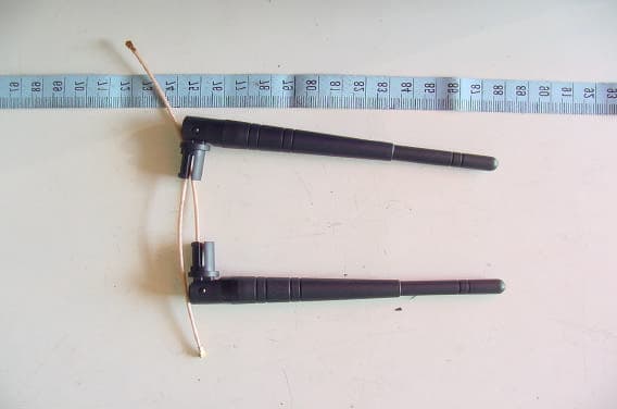
Click to zoom
Application Details
- Equipment Class
- DTS - Digital Transmission System
- Date of Grant
- Nov 16, 2003
- Application Purpose
- Original Equipment
- Date of Application
- Nov 16, 2003
- Equipment Note
- 802.11 b/g Mini-PCI Module
- Frequency Range
- 2412.00000000 - 2462.00000000
- Company
- Abocom Systems Inc
- Country
- Taiwan
Documents & Files
Document Text
Text extracted from the exhibit documents filed with the FCC. Open a document above to read the original.
Users Manual
WMG2400 802.11b/g Wireless miniPCI Card The 802.11g Wireless MiniPCI Card is a device that lets you connect your notebook to a wireless local area network (LAN). A wireless LAN is like a regular LAN, except that you can share information without looking for a place to plug in, and augment networks without installing or moving wires. Based on radio frequency (RF) technology, a wireless LAN transmits and receives data over the air, along with the guarantee to provide privacy and noninterference by the use of separate radio frequency. The 802.11g Wireless MiniPCI Card allows you to take full advantage of your PC’s mobility with access to real-time information and online services anytime and anywhere. Plus, with the network installation simplicity and flexibility, you can eliminate the need to pull cable through walls and ceilings and allow the network to go where wires cannot go. Exploring WWW and augmenting networks can never be done more easily. The 802.11g Wireless MiniPCI Card supports 802.11b and IEEE draft Std 802.11g systems. While the proprietary application of PBCCE technology in 802.11b mode of operation provides data rates up to 22 Mbit/s ,data rates up to 54 Mbit/s may be provided in 802.11g mode of operation. y Complies with IEEE 802.11b standard and draft standard 802.11g for 2.4GHz Wireless LAN. y Type III-b MiniPCI form factor for standard compatibility in a variety of mobile devices y Works with all existing network infrastructure. y Complies with specific wireless products and services. y Capable of up to 256-Bit WEP Encryption. y Freedom to roam while staying connected. y 22-Mbps Packet Binary Convolution Coding (PBCC)( according to the IEEE Std 802.11b high-rate y specification) y Up to 54 Mbps may be provided in 802.11g mode of operation y Complies with Windows98/2000/ME/XP y Lower power consumption. y Easy to install and configure. y Standard IEEE 802.11b, IEEE 802.11g Standard Host Interface Mini PCI 1.0 specification Antenna Internal diversity with connectors Frequency Range 2.412GHz-2.4835GHz Number of Selectable Channels USA, Canada: 11 channels Europe: 13 channels Japan: 14 channels 802.11b: Direct Sequence Spread Spectrum (PBCC, CCK, DQPSK, DBPSK) Modulation Technique 802.11g: Orthogonal frequency division multiplexing 802.11b(22Mbps, 11 Mbps, 5.5 Mbps, 2 Mbps, 1 Mbps) Data Rate 802.11g(54 Mbps, 48 Mbps, 36 Mbps, 24 Mbps, 18 Mbps, 12 Mbps, 9 Mbps, 6 Mbps) 802.11b: Both Short and Long preamble Preamble 802.11g: Long preamble only Security Hardware-Based Encryption/Decryption Using 64-, 128-, and 256-Bit Wired-Equivalent Privacy (WEP) Keys Output Power 54Mbps OFDM: 14dBm;11Mbps CCK: 18dBm Receiver Sensitivity -68dBm at 54Mpbs;-82dBm at 11Mbps Media Access Protocol CSMA/CA (Collision Avoidance) with ACK Power Requirement Operating Voltage: 3.3V WMG2400 802.11b/g Wireless miniPCI Card TX consumption mode:630mA RX consumption mode: T350mA Physical Specifications Weight: 10g Dimension:59.75 (L) x 44.6(W) mm Environment Specifications Operating Temperature: 0~65 ambient temperature Storage Temperature: -20~75 ambient temperature Operating humidity: 95% maximum (non-condensing) Storage humidity: 95% maximum (non-condensing) Supported OS Windows 98 Windows ME Windows 2000 Windows XP EMC Certification FCC Part 15.247 in US Notice : The changes or modifications not expressly approved by the party responsible for compliance could void the user’s authority to operate the equipment. This device complies with part 15 of the FCC Rules. Operation is subject to the following two conditions: 1. This device may not cause harmful interference. 2. This device must accept any interference received, including interference that may cause undesired operation. FCC INFORMATION The Federal Communication Commission Radio Frequency Interference Statement includes the following paragraph: The equipment has been tested and found to comply with the limits for a Class B Digital Device, pursuant to part 15 of the FCC Rules. These limits are designed to provide reasonable protection against harmful interference in a residential installation. This equipment generates, uses and can radiate radio frequency energy and, if not installed and used in accordance with the instruction, may cause harmful interference to radio communication. However, there is no grantee that interference will not occur in a particular installation. If this equipment dose cause harmful interference to radio or television reception, which can be determined by turning the equipment off and on , the user is encouraged to try to correct the interference by one or more of the following measures: --Reorient or relocate the receiving antenna. --Increase the separation between the equipment and receiver. --Connect the equipment into an outlet on a circuit different from that to which the receiver is connected. --Consult the dealer or an experienced radio/TV technician for help. The user should not modify or change this equipment without written approval Form AboCom Systems, Inc. Modification could void authority to use this equipment.
Users Manual
WMG2400 802.11b/g Wireless miniPCI Card The 802.11g Wireless MiniPCI Card is a device that lets you connect your notebook to a wireless local area network (LAN). A wireless LAN is like a regular LAN, except that you can share information without looking for a place to plug in, and augment networks without installing or moving wires. Based on radio frequency (RF) technology, a wireless LAN transmits and receives data over the air, along with the guarantee to provide privacy and noninterference by the use of separate radio frequency. The 802.11g Wireless MiniPCI Card allows you to take full advantage of your PC’s mobility with access to real-time information and online services anytime and anywhere. Plus, with the network installation simplicity and flexibility, you can eliminate the need to pull cable through walls and ceilings and allow the network to go where wires cannot go. Exploring WWW and augmenting networks can never be done more easily. The 802.11g Wireless MiniPCI Card supports 802.11b and IEEE draft Std 802.11g systems. While the proprietary application of PBCCE technology in 802.11b mode of operation provides data rates up to 22 Mbit/s ,data rates up to 54 Mbit/s may be provided in 802.11g mode of operation. y Complies with IEEE 802.11b standard and draft standard 802.11g for 2.4GHz Wireless LAN. y Type III-b MiniPCI form factor for standard compatibility in a variety of mobile devices y Works with all existing network infrastructure. y Complies with specific wireless products and services. y Capable of up to 256-Bit WEP Encryption. y Freedom to roam while staying connected. y 22-Mbps Packet Binary Convolution Coding (PBCC)( according to the IEEE Std 802.11b high-rate y specification) y Up to 54 Mbps may be provided in 802.11g mode of operation y Complies with Windows98/2000/ME/XP y Lower power consumption. y Easy to install and configure. y Standard IEEE 802.11b, IEEE 802.11g Standard Host Interface Mini PCI 1.0 specification Antenna Internal diversity with connectors Frequency Range 2.412GHz-2.4835GHz Number of Selectable Channels USA, Canada: 11 channels Europe: 13 channels Japan: 14 channels 802.11b: Direct Sequence Spread Spectrum (PBCC, CCK, DQPSK, DBPSK) Modulation Technique 802.11g: Orthogonal frequency division multiplexing 802.11b(22Mbps, 11 Mbps, 5.5 Mbps, 2 Mbps, 1 Mbps) Data Rate 802.11g(54 Mbps, 48 Mbps, 36 Mbps, 24 Mbps, 18 Mbps, 12 Mbps, 9 Mbps, 6 Mbps) 802.11b: Both Short and Long preamble Preamble 802.11g: Long preamble only Security Hardware-Based Encryption/Decryption Using 64-, 128-, and 256-Bit Wired-Equivalent Privacy (WEP) Keys Output Power 54Mbps OFDM: 14dBm;11Mbps CCK: 18dBm Receiver Sensitivity -68dBm at 54Mpbs;-82dBm at 11Mbps Media Access Protocol CSMA/CA (Collision Avoidance) with ACK Power Requirement Operating Voltage: 3.3V WMG2400 802.11b/g Wireless miniPCI Card TX consumption mode:630mA RX consumption mode: T350mA Physical Specifications Weight: 10g Dimension:59.75 (L) x 44.6(W) mm Environment Specifications Operating Temperature: 0~65 ambient temperature Storage Temperature: -20~75 ambient temperature Operating humidity: 95% maximum (non-condensing) Storage humidity: 95% maximum (non-condensing) Supported OS Windows 98 Windows ME Windows 2000 Windows XP EMC Certification FCC Part 15.247 in US Notice : The changes or modifications not expressly approved by the party responsible for compliance could void the user’s authority to operate the equipment. This device complies with part 15 of the FCC Rules. Operation is subject to the following two conditions: 1. This device may not cause harmful interference. 2. This device must accept any interference received, including interference that may cause undesired operation. FCC INFORMATION The Federal Communication Commission Radio Frequency Interference Statement includes the following paragraph: The equipment has been tested and found to comply with the limits for a Class B Digital Device, pursuant to part 15 of the FCC Rules. These limits are designed to provide reasonable protection against harmful interference in a residential installation. This equipment generates, uses and can radiate radio frequency energy and, if not installed and used in accordance with the instruction, may cause harmful interference to radio communication. However, there is no grantee that interference will not occur in a particular installation. If this equipment dose cause harmful interference to radio or television reception, which can be determined by turning the equipment off and on , the user is encouraged to try to correct the interference by one or more of the following measures: --Reorient or relocate the receiving antenna. --Increase the separation between the equipment and receiver. --Connect the equipment into an outlet on a circuit different from that to which the receiver is connected. --Consult the dealer or an experienced radio/TV technician for help. The user should not modify or change this equipment without written approval Form AboCom Systems, Inc. Modification could void authority to use this equipment.
Cover Letter(s)
1 Mike Kuo From: S. S. Liou [[email protected]] Sent: November142003Friday 2:56 AM To: Mike Kuo Subject: Re: Abocom System FCC ID:MQ4WMG2K4, AN03T3324 Modular Approval Letter.PDF WMG2400_Antenna _Installation.p... Band Edge Plots for 802.11g mo... WMG2400 Channel Justification.... Revised User Manual.pdf Hi Mike, Ans. #1: please refer to attached file Modular Approval Letter.PDF Ans. #2 and #3: please refer to attached file WMG2400_Antenna_Installation.pdf Ans. #4: please refer to attached file Band Edge Plots for 802.11g mode.pdf Ans. #5: please refer to attached file WMG2400 Channel Justification.pdf Ans. #6: please refer to attached file Revised User Manual.pdf Best regards, ================================ S. S. Liou Engineer / EMC Dep. II ETC ----- Original Message ----- From: "Mike Kuo" <[email protected]> To: "ETC/Iris (E-mail)" <[email protected]>; "Will Yauo (E-mail)" <[email protected]> Sent: Wednesday, October 22, 2003 7:34 AM Subject: Abocom System FCC ID:MQ4WMG2K4, AN03T3324 > Question #1: By reviewing the information submitted in this application, it > appears that this 802.11 b/g mini-PCI card is seeking full module approval. > Please provide a request for module approval cover letter to address each of > 9 criteria per FCC DA00-1407. > > Question #2: Please provide OEM installation instruction for each of > antennas. Please make sure to provide the required antenna location when > this device is used in the notebook computer. > > Question #3: By looking at the PIFA Antenna / C068- 510273- A showed in the > external photos, the antenna cable length is not long enough to provide 20 > cm separation distance when this type of antenna is installed in the > notebook computer. If this is the case, then when mini-PCI module is using > with PIFA antenna, the RF exposure condition will become portable. Based > upon FCC policy, no grant will be issued for portable module approval. > Portable module approval can only be granted in a dedicated host. > > Question #4: Please provide band edge plots for 802.11g mode. In the Test > report -3, power spectra density plots were placed in this section. > > Question #5: Per the information given in the user manual, this device is > capable of operating up to 2483.5MHz which is not allowed in the U.S. This > device only investigated with 11 channel operation with highest channel at > 2462MHz. Please provide technical information on how the device will be > limited to operate with authorized channel in the U.S.. > 2 > Question #6:RF Exposure information provided in the user manual does not > provide proper statement to limit this device to be used as mobile device. > Please provide revised user manual. > > Best Regards > > Mike Kuo > Compliance Certification Services > 561F Monterey Road > Morgan Hill CA 95037 > Tel: (408)463-0885 x: 105 > Fax: (408)463-0888 > http://www.ccsemc.com >
Cover Letter(s)
AboCom Systems, Inc. Head Office: 1F, No. 21, R&D Rd. II, SBIP, Hsin-Chu 300, Taiwan, R.O.C. Factory: No. 77, Yu-Yih Rd., Chu-Nan Chen, Miao-Lih Hsian 350, Taiwan, R.O.C. Mobile Interconnected Products: 8F, No. 123, Lane 235, Bao-Chiao Rd, Hsin-Tien City, Taipei 231, Taiwan, R.O.C. TEL: +886-37-580-777 FAX: +886-37-580-799 http://www.abocom.com Request for modular approval – FCC ID: MQ4WMG2K4 Dear Application Examiner, The AboCom Product Development The 802.11b/g Wireless MiniPCI Card Module WMG2400 is seeking FCC authorization as a module transmitter. The requirement of the FCC Public notice DA00-1407 are met. The following requirement are fulfilled: 1. The module transmitter must have its own shielding The radio portion of the module is contained in its own RF shielding. See the external photos. 2. The modular transmitter must have buffered modulation /data inputs The module has a memory management unit inside of the IC. It buffers the data inputs from UART and MiniPCI terminal. 3. The modular transmitter must have its own power supply regulation The IC contains an own voltage regulation. In case of change in the supply voltage VCCfor example cause by temperature changes or other effect,the internal voltage will be stabilized. 4. The modular transmitter must comply with the antenna requirement of Section 15.203 and 15.204c The transmitter shall only be used with the tested integral antenna or with an antenna that has less antenna gain. Requirement for the use of external antennas are specified in the antenna information exhibit.See LCT Antenna F1B-003404-52F1B-303706-52F1B-303709-93 Wanshih Antenna SWJ-0007AW111-094-D8 5. The modular transmitter must be tested in a stand-alone configuration The EUT was tested in a stand-alone configuration. The module was fixed in test/programming board during the test. See also the test report and Test setup photos. AboCom Systems, Inc. Head Office: 1F, No. 21, R&D Rd. II, SBIP, Hsin-Chu 300, Taiwan, R.O.C. Factory: No. 77, Yu-Yih Rd., Chu-Nan Chen, Miao-Lih Hsian 350, Taiwan, R.O.C. Mobile Interconnected Products: 8F, No. 123, Lane 235, Bao-Chiao Rd, Hsin-Tien City, Taipei 231, Taiwan, R.O.C. TEL: +886-37-580-777 FAX: +886-37-580-799 http://www.abocom.com 6. The modular transmitter must be labeled with its own FCC ID number The EUT will be labeled with its own FCC ID number. If the module is installed inside of an end-product, the label will not be visible. 7. The modular transmitter must comply with any rule or operating requirement applicable to the transmitter and the manufacturer must provide adequate instruction along with the module to explain any such requirements. The EUT is compliant with all applicable FCC rules. Detail instructions are given in the Users Guide. 8. The modular transmitter must comply with any applicable RF exposure requirements. The transmitter herein was tested with the antenna that is integrated on the radio module. Compliance to RF exposure requirements for this antenna is included within this application for approval. Appropriate warning statement will be placed with each end product user information based on the results of the RF exposure data filed with this application. OEM Resellers will be advised to include a similar statement to inform the users of any requirements for RF safety. Please contact us if you have any addition questions. Best Regards, Iris Huang Abocom Systems ,Inc. 1F, No. 21, R&D Rd. II, SBIP, Hsin-Chu 300, Taiwan, R.O.C. Tel:886-3-578-9090 Fax:886-3-578-9520
Cover Letter(s)
Question #2: Please provide OEM installation instruction for each of antennas. Please make sure to provide the required antenna location when this device is used in the notebook computer. [Answer] All the antennas tested for WMG2400 will not be used in the notebook computer or laptop but the antennas will be installed in the desktop computer with PCI extended adapter. (Please see the figures). The notebook computer manufacturers have their own antennas to fit their design. If we ship WMG2400 to the notebook computer manufacturer, we will apply another FCC test with another antenna. For PIFA antenna, it has 20cm cable length, it will be installed inside wireless router only. ( in a dedicated host, not in portable device or notebook computer) Except PIFA antenna, the other five antennas will be installed in PCI extended card and wireless router. (or wireless access point. Please see the figures) Question #3: By looking at the PIFA Antenna /C068-510273 – A showed in the external photos, the antenna cable length is not long enough to provide 20cm separation distance when this type of antenna is installed in the notebook computer. If this is the case, then when mini-PCI module is using with PIFA antenna, the RF exposure condition will become portable module approval. Portable module approval can only be granted in a dedicated host. [Answer] We guarantee that we will not install this PIFA antenna with 20cm cable length in the notebook computer. We only install this PIFA antenna with 20cm cable length inside access point, not portable device. If we want to install PIFA antenna in other dedicated host device or lengthen the cable length, we will apply another FCC test again.
External Photos
ETC Report No. : ET92R-08-115 FCC ID.: MQ4WMG2K4 Rev. No 1.0 CONSTRUCTED PHOTOS of EUT Front View of Antenna (PIFA Antenna / C068-510273-A) Front View of Antenna (2.4GHz Dipole Antenna x 2 / F1B-003404-52) ETC Report No. : ET92R-08-115 FCC ID.: MQ4WMG2K4 Rev. No 1.0 CONSTRUCTED PHOTOS of EUT Front View of Antenna (Dipole Antenna / SJW-0007A) Front View of Antenna (2.4GHz Dipole Antenna / F1B-003404-52) ETC Report No. : ET92R-08-115 FCC ID.: MQ4WMG2K4 Rev. No 1.0 CONSTRUCTED PHOTOS of EUT Front View of Antenna (2.4/4.9-5.85 GHz Swivel Antenna SMA / F1B-303706-52) Front View of Antenna (2.4G Antenna / W111-094-D8)
ID Label/Location Info
FCC Label 22 2 mm This statement will be placed in User’s Manual: This device complies with part 15 of the FCC Rules. Operation is subject to the following two conditions: 1. This device may not cause harmful interference. 2. This device must accept any interference received, including interference that may cause undesired operation.
Internal Photos
ETC Report No. : ET92R-08-115 FCC ID.: MQ4WMG2K4 Rev. No 1.0 CONSTRUCTED PHOTOS of EUT Component View of Main PCB Solder View of Main PCB ETC Report No. : ET92R-08-115 FCC ID.: MQ4WMG2K4 Rev. No 1.0 CONSTRUCTED PHOTOS of EUT Component View of Main PCB Solder View of Main PCB
Test Report
Rev. No 2.0 FCC Part 15 EMI TEST REPORT of E.U.T. : MiniPCI WLAN Adapter (802.11b/g) FCC ID. : MQ4WMG2K4 MODEL : WMG2400 for APPLICANT : AboCom Systems , Inc ADDRESS : 1F, No.21, R&D Rd.II,SBIP,Hsin-Chu 300, Taiwan,R.O.C. Test Performed by ELECTRONICS TESTING CENTER, TAIWAN NO. 34, LIN 5, DING FU TSUN, LINKOU HSIANG TAIPEI HSIEN, TAIWAN, R.O.C. Tel : (02)26023052 Fax : (02)26010910 http://www.etc.org.tw ; e-mail: [email protected] Report Number : ET92R-08-115 ETC Report No. : ET92R-08-115 FCC ID.:MQ4WMG2K4 Rev. No 1.0 TEST REPORT CERTIFICATION Applicant : AboCom Systems , Inc 1F, No.21, R&D Rd.II,SBIP,Hsin-Chu 300,Taiwan,R.O.C. Manufacturer : AboCom Systems , Inc No.77, Yu-Yih Rd.,Chu-Nan Chen,Miao-Lih Hsuan350, Taiwan,R.O.C. Description of EUT : a) Type of EUT : MiniPCI WLAN Adapter (802.11b/g) b) Trade Name : AboCom c) Model No. : WMG2400 d) Power Supply : From Notebook PC Regulation Applied : FCC Rules and Regulations Part 15 Subpart B & C (2002) I HEREBY CERTIFY THAT: The data shown in this report were made in accordance with the procedures given in ANSI C63.4, and the energy emitted by the device was founded to be within the limits applicable. I assume full responsibility for accuracy and completeness of these data. Note: 1. The result of the testing report relate only to the item tested. 2. The testing report shall not be reproduced expect in full, without the written approval of ETC. Issued Date : Sep 15, 2003 Test Engineer : ( Michael Chen ) Approve & Authorized Signer : Will Yauo, Manager EMC Dept. II of ELECTRONICS TESTING CENTER, TAIWAN ETC Report No. : ET92R-08-115 FCC ID.:MQ4WMG2K4 Rev. No 1.0 Table of Contents Page 1 GENERAL INFORMATION.......................................................................................................1 1.1 Product Description........................................................................................................................1 1.2 Characteristics of Device................................................................................................................1 1.3 Test Methodology..........................................................................................................................1 1.4 Test Facility....................................................................................................................................1 2 PROVISIONS APPLICABLE.......................................................................................................2 2.1 Definition........................................................................................................................................2 2.2 Requirement for Compliance...........................................................................................................3 2.3 Restricted Bands of Operation........................................................................................................5 2.4 Labeling Requirement.....................................................................................................................5 2.5 User Information............................................................................................................................6 3. SYSTEM TEST CONFIGURATION...........................................................................................7 3.1 Justification.....................................................................................................................................7 3.2 Devices for Tested System.............................................................................................................7 4 RADIATED EMISSION MEASUREMENT..............................................................................8 4.1 Applicable Standard.......................................................................................................................8 4.2 Measurement Procedure.................................................................................................................8 4.3 Measuring Instrument...................................................................................................................10 4.4 Radiated Emission Data................................................................................................................11 4.4.1 RF Portion................................................................................................................................11 4.4.2 Radiated Eimssion of Restricted bands......................................................................................47 4.4.3 Other Emission........................................................................................................................53 4.5 Field Strength Calculation.............................................................................................................64 4.6 Photos of Radiation Measuring Setup............................................................................................65 5 CONDUCTED EMISSION MEASUREMENT.........................................................................71 5.1 Standard Applicable.....................................................................................................................71 5.2 Measurement Procedure...............................................................................................................71 5.3 Conducted Emission Data.............................................................................................................72 5.4 Result Data Calculation.................................................................................................................75 5.5 Conducted Measurement Equipment.............................................................................................76 5.6 Photos of Conduction Measuring Setup........................................................................................77 6 ANTENNA REQUIREMENT..........................................…
Text truncated - open the document above for the full version.
Test Report
ETC Report No. : ET92R-08-115 Sheet 31 of 52Sheets FCC ID.: MQ4WMG2K4 Rev. No 2.0 ETC Report No. : ET92R-08-115 Sheet 32 of 52Sheets FCC ID.: MQ4WMG2K4 Rev. No 2.0
Test Report
ETC Report No. : ET92R-08-115 Sheet 1 of 52Sheets FCC ID.: MQ4WMG2K4 Rev. No 2.0 Appendix 1 : Ploted Datas of Power Line Conducted Emissions ETC Report No. : ET92R-08-115 Sheet 2 of 52Sheets FCC ID.: MQ4WMG2K4 Rev. No 2.0 ETC Report No. : ET92R-08-115 Sheet 3 of 52Sheets FCC ID.: MQ4WMG2K4 Rev. No 2.0 ETC Report No. : ET92R-08-115 Sheet 4 of 52Sheets FCC ID.: MQ4WMG2K4 Rev. No 2.0 ETC Report No. : ET92R-08-115 Sheet 5 of 52Sheets FCC ID.: MQ4WMG2K4 Rev. No 2.0 ETC Report No. : ET92R-08-115 Sheet 6 of 52Sheets FCC ID.: MQ4WMG2K4 Rev. No 2.0 ETC Report No. : ET92R-08-115 Sheet 7 of 52Sheets FCC ID.: MQ4WMG2K4 Rev. No 2.0 ETC Report No. : ET92R-08-115 Sheet 8 of 52Sheets FCC ID.: MQ4WMG2K4 Rev. No 2.0 ETC Report No. : ET92R-08-115 Sheet 9 of 52Sheets FCC ID.: MQ4WMG2K4 Rev. No 2.0 ETC Report No. : ET92R-08-115 Sheet 10 of 52Sheets FCC ID.: MQ4WMG2K4 Rev. No 2.0 ETC Report No. : ET92R-08-115 Sheet 11 of 52Sheets FCC ID.: MQ4WMG2K4 Rev. No 2.0 ETC Report No. : ET92R-08-115 Sheet 12 of 52Sheets FCC ID.: MQ4WMG2K4 Rev. No 2.0 ETC Report No. : ET92R-08-115 Sheet 13 of 52Sheets FCC ID.: MQ4WMG2K4 Rev. No 2.0 ETC Report No. : ET92R-08-115 Sheet 14 of 52Sheets FCC ID.: MQ4WMG2K4 Rev. No 2.0 Appendix 2 : Ploted Datas of Emissions Bandwidth ETC Report No. : ET92R-08-115 Sheet 15 of 52Sheets FCC ID.: MQ4WMG2K4 Rev. No 2.0 ETC Report No. : ET92R-08-115 Sheet 16 of 52Sheets FCC ID.: MQ4WMG2K4 Rev. No 2.0 ETC Report No. : ET92R-08-115 Sheet 17 of 52Sheets FCC ID.: MQ4WMG2K4 Rev. No 2.0 ETC Report No. : ET92R-08-115 Sheet 18 of 52Sheets FCC ID.: MQ4WMG2K4 Rev. No 2.0 ETC Report No. : ET92R-08-115 Sheet 19 of 52Sheets FCC ID.: MQ4WMG2K4 Rev. No 2.0 ETC Report No. : ET92R-08-115 Sheet 20 of 52Sheets FCC ID.: MQ4WMG2K4 Rev. No 2.0 ETC Report No. : ET92R-08-115 Sheet 21 of 52Sheets FCC ID.: MQ4WMG2K4 Rev. No 2.0 Appendix 3 : Ploted Datas of Output Peak Power ETC Report No. : ET92R-08-115 Sheet 22 of 52Sheets FCC ID.: MQ4WMG2K4 Rev. No 2.0 ETC Report No. : ET92R-08-115 Sheet 23 of 52Sheets FCC ID.: MQ4WMG2K4 Rev. No 2.0 ETC Report No. : ET92R-08-115 Sheet 24 of 52Sheets FCC ID.: MQ4WMG2K4 Rev. No 2.0 ETC Report No. : ET92R-08-115 Sheet 25 of 52Sheets FCC ID.: MQ4WMG2K4 Rev. No 2.0 ETC Report No. : ET92R-08-115 Sheet 26 of 52Sheets FCC ID.: MQ4WMG2K4 Rev. No 2.0 ETC Report No. : ET92R-08-115 Sheet 27 of 52Sheets FCC ID.: MQ4WMG2K4 Rev. No 2.0
Test Report
ETC Report No. : ET92R-08-115 Sheet 28 of 52Sheets FCC ID.: MQ4WMG2K4 Rev. No 2.0 Appendix 4 : Ploted Datas of Band Edge Emission ETC Report No. : ET92R-08-115 Sheet 29 of 52Sheets FCC ID.: MQ4WMG2K4 Rev. No 2.0 ETC Report No. : ET92R-08-115 Sheet 30 of 52Sheets FCC ID.: MQ4WMG2K4 Rev. No 2.0 ETC Report No. : ET92R-08-115 Sheet 31 of 52Sheets FCC ID.: MQ4WMG2K4 Rev. No 2.0 ETC Report No. : ET92R-08-115 Sheet 32 of 52Sheets FCC ID.: MQ4WMG2K4 Rev. No 2.0 ETC Report No. : ET92R-08-115 Sheet 33 of 52Sheets FCC ID.: MQ4WMG2K4 Rev. No 2.0 Appendix 5 : Ploted Datas of Power Density ETC Report No. : ET92R-08-115 Sheet 34 of 52Sheets FCC ID.: MQ4WMG2K4 Rev. No 2.0 ETC Report No. : ET92R-08-115 Sheet 35 of 52Sheets FCC ID.: MQ4WMG2K4 Rev. No 2.0 ETC Report No. : ET92R-08-115 Sheet 36 of 52Sheets FCC ID.: MQ4WMG2K4 Rev. No 2.0 ETC Report No. : ET92R-08-115 Sheet 37 of 52Sheets FCC ID.: MQ4WMG2K4 Rev. No 2.0 ETC Report No. : ET92R-08-115 Sheet 38 of 52Sheets FCC ID.: MQ4WMG2K4 Rev. No 2.0 ETC Report No. : ET92R-08-115 Sheet 39 of 52Sheets FCC ID.: MQ4WMG2K4 Rev. No 2.0 ETC Report No. : ET92R-08-115 Sheet 40 of 52Sheets FCC ID.: MQ4WMG2K4 Rev. No 2.0 Appendix 6 : Plotted Data for Out-of-Band Conducted Emission ETC Report No. : ET92R-08-115 Sheet 41 of 52Sheets FCC ID.: MQ4WMG2K4 Rev. No 2.0 ETC Report No. : ET92R-08-115 Sheet 42 of 52Sheets FCC ID.: MQ4WMG2K4 Rev. No 2.0 ETC Report No. : ET92R-08-115 Sheet 43 of 52Sheets FCC ID.: MQ4WMG2K4 Rev. No 2.0 ETC Report No. : ET92R-08-115 Sheet 44 of 52Sheets FCC ID.: MQ4WMG2K4 Rev. No 2.0 ETC Report No. : ET92R-08-115 Sheet 45 of 52Sheets FCC ID.: MQ4WMG2K4 Rev. No 2.0 ETC Report No. : ET92R-08-115 Sheet 46 of 52Sheets FCC ID.: MQ4WMG2K4 Rev. No 2.0 ETC Report No. : ET92R-08-115 Sheet 47 of 52Sheets FCC ID.: MQ4WMG2K4 Rev. No 2.0 ETC Report No. : ET92R-08-115 Sheet 48 of 52Sheets FCC ID.: MQ4WMG2K4 Rev. No 2.0 ETC Report No. : ET92R-08-115 Sheet 49 of 52Sheets FCC ID.: MQ4W…
Text truncated - open the document above for the full version.
Contact Information
Applicant
Harry Huang(Manager)
Test Firm
Electronics Testing Center, TaiwanWin-Po Tsai
Technical Specifications
| # | Rule Parts | Frequency Range | Power Output |
|---|---|---|---|
| 1 | 15C | 2.41 GHz - 2.46 GHz | 57.50 mW |
Other Applications from Abocom Systems Inc

MQ4WM5208
Oct 27, 2015802.11b/g/n Module
Equipment Class
DTS - Digital Transmission System
MQ4AM7221
Mar 18, 20152T2R 802.11b/g/n/ac Module
Equipment Class
DTS - Digital Transmission System
MQ4PLW72
Mar 18, 201511ac WiFi Extender Smart Plug / 11ac WiFi Extender
Equipment Class
NII - Unlicensed National Information Infrastructure TX
MQ4CB1522M
Sep 22, 2014IP Camera
Equipment Class
DTS - Digital Transmission System
MQ4-MBR-1100
Sep 21, 2014Android TV Dongle
Equipment Class
JBC - Part 15 Class B Computing Device/Personal Computer