MQ4WP102802.11b WLAN Access Point
Abocom Systems Inc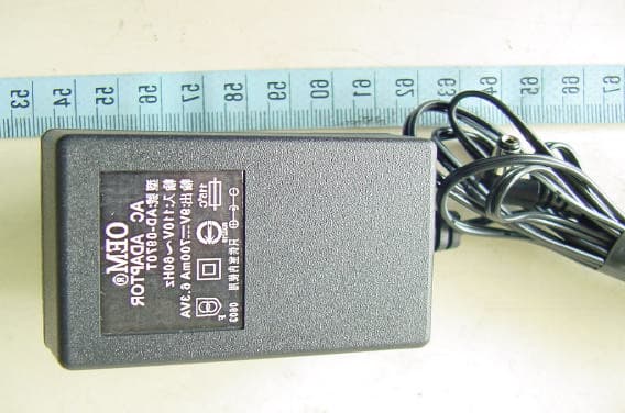
Click to zoom
Application Details
- Equipment Class
- DTS - Digital Transmission System
- Date of Grant
- Nov 17, 2003
- Application Purpose
- Original Equipment
- Date of Application
- Nov 17, 2003
- Equipment Note
- 802.11b WLAN Access Point
- Frequency Range
- 2412.00000000 - 2462.00000000
- Company
- Abocom Systems Inc
- Country
- Taiwan
Documents & Files
Document Text
Text extracted from the exhibit documents filed with the FCC. Open a document above to read the original.
Users Manual
1 WP102 802.11b Wireless Access Point User’s Guide 2 FCC Certifications This equipment has been tested and found to comply with the limits for a Class B digital device, pursuant to Part 15 of the FCC Rules. These limits are designed to provide reasonable protection against harmful interference in a residential installation. This equipment generates, uses and can radiate radio frequency energy and, if not installed and used in accordance with the instructions, may cause harmful interference to radio communications. However, there is no guarantee that interference will not occur in a particular installation. If this equipment does cause harmful interference to radio or television reception, which can be determined by turning the equipment off and on, the user is encouraged to try to correct the interference by one or more of the following measures: y Reorient or relocate the receiving antenna. y Increase the separation between the equipment and receiver. y Connect the equipment into an outlet on a circuit different from that to which the receiver is connected. y Consult the dealer or an experienced radio/TV technician for help. CAUTION: Any changes or modifications not expressly approved by the grantee of this device could void the user’s authority to operate the equipment. This device complies with Part 15 of the FCC rules. Operation is subject to the following two conditions: (1) This device may not cause harmful interference, and (2) This device must accept any interference received, including interference that may cause undesired operation. FCC RF Radiation Exposure Statement This equipment complies with FCC RF radiation exposure limits set forth for an uncontrolled environment. This equipment should be installed and operated with a minimum distance of 20cm between the radiator and your body. CE Mark Warning This is a Class B product. In a domestic environment, this product may cause radio interference, in which case the user may be required to take adequate measures. All trademarks and brand names are the property of their respective proprietors. Specifications are subject to change without prior notification. 3 Catalog Introduction .....................................................................................................4 How to connect to the web server of AP .........................................................4 Upgrade Firmware in AP.................................................................................9 Save/Reload Settings of AP...........................................................................10 Set Account and Password for accessing web server of AP.......................... 11 4 Introduction The WP102 is an IEEE802.11b compliant Access Point, which provides a powerful high-speed wireless connection for compatible wireless-enabled devices into the network with the freedom to roam. The WP102 provides 64/128 bit WEP encryption and IEEE802.1x which ensures a high level of security to protects users’ data and privacy. The MAC Address filter prevents the unauthorized MAC Addresses from accessing your Wireless LAN. Your network security is therefore double assured. Plus, the web-based management is easy to use that your wireless network connection is ensured to be always solid and hassle free. How to connect to the web server of AP In order to configure the settings of AP, you have to connect to the web server of AP first. (1) The default IP of AP is 192.168.1.254, in order to connect to the web server of AP (a) connect PC to the AP through a UTP cable, the connection is like the following graph. Or, you can also connect to the AP by a wireless network card and follow the same steps. (b) set the IP of LAN card in PC to the same subnet as the IP of AP 5 6 (c) Open IE and key in IP address of AP, then you can access the web server of AP and configure AP through web pages. You will see the following web page. Note: If you have changed the default IP of AP and forget current IP of AP, you can connect to the AP through COM port terminal program to get the IP. In this case, please refer to (2). (2) Get the IP of AP through COM port terminal program (a) You have to connect to the AP through COM port terminal program to get the IP. The connection is like the following graph. 7 The basic setting of the terminal program is baud rate: 38400 bps, 8-N-1, no flow control. Please refer to the following graph. (b) Choose “COM#” in “Connect To” dialog (c) Set 38400 bps, 8-N-1, no flow control for “Port Settings” 8 (d) Push “Enter” key , then the “#” will appear. Enter “ifconfig br0”, then push “Enter” key. You will see the IP of AP. (e) Follow the steps in (1) to connect to the server of AP. 9 Upgrade Firmware in AP While you get a new version of firmware of AP, you could upgrade it on web page. (1) Select the “Upgrade Firmware” web page and select a firmware image file, then push “Upload”. Wait for a while, the firmware will be updated. 10 Save/Reload Settings of AP You can save current settings of AP to a file or reload the settings from the file which was saved previously. Besides, you could reset the current configuration to factory default (1) Select the “Save/Reload Settings” web page. 11 Set Account and Password for accessing web server of AP For secure reason, you could set the account to access the web server of Access Point. Empty user name and password will disable the protection. After you have succeeded to set the account and password, next time, you will be asked to input the account/password to access the web server. (1) Select the “Password” web page and input the account/password. 12 (2) Input the account/password to access the web pages.
External Photos
ETC Report No. : ET92R-09-021-04 FCC ID.: MQ4WP102 Rev. No 1.0 CONSTRUCTED PHOTOS of EUT Front View of EUT Rear View of EUT ETC Report No. : ET92R-09-021-04 FCC ID.: MQ4WP102 Rev. No 1.0 CONSTRUCTED PHOTOS of EUT Side View of EUT Side View of EUT ETC Report No. : ET92R-09-021-04 FCC ID.: MQ4WP102 Rev. No 1.0 CONSTRUCTED PHOTOS of EUT Front View of Adaptor Rear View of Adaptor
ID Label/Location Info
FCC Label This statement will be placed in User’s Manual: This device complies with part 15 of the FCC Rules. Operation is subject to the following two conditions: 1.This device may not cause harmful interference. 2.This device must accept any interference received, including interference that may cause undesired operation.
Internal Photos
ETC Report No. : ET92R-09-021-04 FCC ID.: MQ4WP102 Rev. No 1.0 CONSTRUCTED PHOTOS of EUT Internal View of EUT Component View of Main PCB ETC Report No. : ET92R-09-021-04 FCC ID.: MQ4WP102 Rev. No 1.0 CONSTRUCTED PHOTOS of EUT Component View of Main PCB Solder View of Main PCB ETC Report No. : ET92R-09-021-04 FCC ID.: MQ4WP102 Rev. No 1.0 CONSTRUCTED PHOTOS of EUT Internal View of Adaptor ETC Report No. : ET92R-09-021-04 FCC ID.: MQ4WP102 Rev. No 1.0 CONSTRUCTED PHOTOS of EUT Component View of Adaptor’s PCB Solder View of Adaptor’s PCB
Operational Description
Page 1 of 3 This document is copyrighted and may not be copied or disclosed to a third party without the specific written authority of AboCom. Copyright AboCom Systems, Inc. 2001. COMPANY CONFIDENTIAL: NOT FOR EXTERNAL DISTRIBUTION Operational Description Model Name: WP102 Author: Jason Date: 2003/9/12 R&D /Gateway Division AboCom Systems, Inc. 1F, No.21, R&D Rd.II, Science-based Industrial Park, Hsinchu,300, Taiwan, ROC Page 2 of 3 This document is copyrighted and may not be copied or disclosed to a third party without the specific written authority of AboCom. Copyright AboCom Systems, Inc. 2001. COMPANY CONFIDENTIAL: NOT FOR EXTERNAL DISTRIBUTION WP102 circuit design: 1. CPU: U1, RTL8181,It is a Lexra LX5280 32-bit RISC processor integrated, operation frequency is 200MHzIt needs an external 44MHz crystal for reference frequencyThis crystal is also used for RF moduleThis chip is responsible to control Ethernet port , RF module, Flash , SDRAM and LEDThis chip includes two fast Ethernet MAC and an IEEE802.11b WLAN MAC+Baseband processor 2. SWITCH: U5, RTL8305SB Rev. D, It is a 5-port Fast Ethernet switch controller that integrates memory, five MACs, and five physical layer transceivers for 10Base-T and 100Base-TX operation into a single chip It contains 1K entry address look-up table It supports 5 VLAN groups and QoS function It supports IEEE802.3x full duplex flow control and back pressure half duplex flow control 3. FLASH: U2, MX29LV160ABTC-90, 16Mbits Flash, bottom sector, 90nsIt is used to store the normal and test firmware 4. SDRAM: U3, U4, EM638165TS-7, 4M x 16 bits SDRAM, Access time 7ns, Clock rate 143MHz 5. RF Transceiver: U8, SA2400A, It is used to do signal modulation and have frequency up-converter and down- converter integratedIt supports DSSS and CCK modulation 6. RF PA: U6, GA2P4W22, It is used to increase power of TX path 7. Power part: There are three regulators are used on the base boardIt is U13 (CS51031), U10 (AIC1117), and U12 (SP6201) U13 is used to transfer 3.3V voltage to provide the all IC which operate at 3.3VU10 is used to transfer 3.3V to 1.8V voltageU12 is used to transfer 3.3V to 3.0V 8. Reset bottom: SW1, It is a factory reset 9. LED part: LED1 indicates power ON LED2 indicates software bug LED3 indicates Link/Act for WLAN port LED4, LED5, and LED6 indicate WEP, MAC enable, and Bridge mode LED7, LED8 indicates Link/Act for two LAN port Page 3 of 3 This document is copyrighted and may not be copied or disclosed to a third party without the specific written authority of AboCom. Copyright AboCom Systems, Inc. 2001. COMPANY CONFIDENTIAL: NOT FOR EXTERNAL DISTRIBUTION RF Module circuit design: (1) Power part RF transceiver is operated at 3.0V, and RF PA is operated at 3.3V (2) RF Transceiver (U8, SA2400A) This chip is a fully integrated single IC RF transceiver designed for 2.45GHz WLAN applicationsIt has features as below. Support IEEE 802.11and 802.11b radios Support IEEE 802.11 DSSS transmission mode Support TX data rate : 1, 2, 5.5, 11Mbps ( DBPSK is for 1Mbps, DQPSK is for 2Mbps, and CCK is for 5.5 and 11Mbps) Combine a low-noise AGC, TX and RX mixers, VCO, synthesizer and Zero IF Quadrature down-converters from 2.45GHz RF directly to Zero IF An I/Q up-converter from base band directly to 2.45GHz +5 dBm maximum output Support 3-wire bus for control (3)2.4GHz Band Pass Filter FL1,ACX BF3225 Band Pass Filter is used to decrease the out band spurious Pass Band 2400~2500MHz Insertion Loss 2.5dB Max. VSWR 2.0 Max. (4)TX/RX Switch U9, AS179-92 When the TX/RX switching, it is provide the fast switch ability Insertion Loss: 0.4 dB @2.0~3.0 dB Isolation: 20 dB min @2.0~3.0 dB (5)Power Amplifier U8, GA2P4W22 This PA is +22.5 dBm/2.4GHz Power Amplifier RFIC It is used to increase the output power It operates at 3.3V Output power: 22.5 dBm (Typical at ACPR ) Small signal gain: 30dB (Typical) 50ohm internal input and output matching
Test Report
Rev. No 2.0 FCC Part 15 EMI TEST REPORT of E.U.T. : 802.11b Wireless Access Point FCC ID. : MQ4WP102 MODEL : WP102 for APPLICANT : AboCom Systems, Inc. ADDRESS : 1F, No. 21, R&D Road II, SBIP, Hsinchu City, Taiwan, R.O.C. Test Performed by ELECTRONICS TESTING CENTER, TAIWAN NO. 34, LIN 5, DING FU TSUN, LINKOU HSIANG TAIPEI HSIEN, TAIWAN, R.O.C. Tel : (02)26023052 Fax : (02)26010910 http://www.etc.org.tw ; e-mail: [email protected] Report Number : ET92R-09-021-04 ETC Report No. : ET92R-09-021-04 FCC ID.: MQ4WP102 Rev. No 1.0 TEST REPORT CERTIFICATION Applicant : AboCom Systems, Inc. 1F, No. 21, R&D Road II, SBIP, Hsinchu City, Taiwan, R.O.C. Manufacturer : AboCom Systems, Inc. 1F, No. 21, R&D Road II, SBIP, Hsinchu City, Taiwan, R.O.C. Description of EUT : a) Type of EUT : 802.11b Wireless Access Point b) Trade Name : AboCom c) Model No. : WP102 d) Power Supply : Adapter I/P: 110Vac/60Hz ; O/P: 9Vdc, 700mA, 6.3Vac Regulation Applied : FCC Rules and Regulations Part 15 Subpart B & C (2002) I HEREBY CERTIFY THAT: The data shown in this report were made in accordance with the procedures given in ANSI C63.4, and the energy emitted by the device was founded to be within the limits applicable. I assume full responsibility for accuracy and completeness of these data. Note: 1. The result of the testing report relate only to the item tested. 2. The testing report shall not be reproduced expect in full, without the written approval of ETC. Issued Date : Sep. 25, 2003 Test Engineer : ( Kevin Lee ) Approve & Authorized Signer : Will Yauo, Manager EMC Dept. II of ELECTRONICS TESTING CENTER, TAIWAN ETC Report No. : ET92R-09-021-04 FCC ID.: MQ4WP102 Rev. No 1.0 Table of Contents Page 1 GENERAL INFORMATION.......................................................................................................1 1.1 Product Description........................................................................................................................1 1.2 Characteristics of Device................................................................................................................1 1.3 Test Methodology..........................................................................................................................1 1.4 Test Facility....................................................................................................................................1 2 PROVISIONS APPLICABLE.......................................................................................................2 2.1 Definition........................................................................................................................................2 2.2 Requirement for Compliance...........................................................................................................3 2.3 Restricted Bands of Operation........................................................................................................5 2.4 Labeling Requirement.....................................................................................................................5 2.5 User Information............................................................................................................................6 3. SYSTEM TEST CONFIGURATION...........................................................................................7 3.1 Justification.....................................................................................................................................7 3.2 Devices for Tested System.............................................................................................................7 4 RADIATED EMISSION MEASUREMENT..............................................................................8 4.1 Applicable Standard.......................................................................................................................8 4.2 Measurement Procedure.................................................................................................................8 4.3 Measuring Instrument...................................................................................................................10 4.4 Radiated Emission Data................................................................................................................11 4.4.1 RF Portion...............................................................................................................................11 4.4.2 Radiated Eimssion of Restricted bands......................................................................................14 4.4.3 Other Emission........................................................................................................................15 4.5 Field Strength Calculation.............................................................................................................15 4.6 Photos of Radiation Measuring Setup............................................................................................16 5 CONDUCTED EMISSION MEASUREMENT........................................................................17 5.1 Standard Applicable.....................................................................................................................17 5.2 Measurement Procedure...............................................................................................................17 5.3 Conducted Emission Data.............................................................................................................18 5.4 Result Data Calculation.................................................................................................................19 5.5 Conducted Measurement Equipment.............................................................................................20 5.6 Photos of Conduction Measuring Setup........................................................................................21 6 ANTENNA REQUIREMENT....…
Text truncated - open the document above for the full version.
Test Report
ETC Report No. : ET92R-09-021-04 Sheet 10 of 29Sheets FCC ID.: MQ4WP102 Rev. No 2.0 ETC Report No. : ET92R-09-021-04 Sheet 11 of 29Sheets FCC ID.: MQ4WP102 Rev. No 2.0 ETC Report No. : ET92R-09-021-04 Sheet 12 of 29Sheets FCC ID.: MQ4WP102 Rev. No 2.0 Appendix 3 : Ploted Datas of Output Peak Power ETC Report No. : ET92R-09-021-04 Sheet 13 of 29Sheets FCC ID.: MQ4WP102 Rev. No 2.0 ETC Report No. : ET92R-09-021-04 Sheet 14 of 29Sheets FCC ID.: MQ4WP102 Rev. No 2.0 ETC Report No. : ET92R-09-021-04 Sheet 15 of 29Sheets FCC ID.: MQ4WP102 Rev. No 2.0 ETC Report No. : ET92R-09-021-04 Sheet 16 of 29Sheets FCC ID.: MQ4WP102 Rev. No 2.0 Appendix 4 : Ploted Datas of Band Edge Emission ETC Report No. : ET92R-09-021-04 Sheet 17 of 29Sheets FCC ID.: MQ4WP102 Rev. No 2.0 ETC Report No. : ET92R-09-021-04 Sheet 18 of 29Sheets FCC ID.: MQ4WP102 Rev. No 2.0 ETC Report No. : ET92R-09-021-04 Sheet 19 of 29Sheets FCC ID.: MQ4WP102 Rev. No 2.0 Appendix 5 : Ploted Datas of Power Density
Test Report
ETC Report No. : ET92R-09-021-04 Sheet 20 of 29Sheets FCC ID.: MQ4WP102 Rev. No 2.0 ETC Report No. : ET92R-09-021-04 Sheet 21 of 29Sheets FCC ID.: MQ4WP102 Rev. No 2.0 ETC Report No. : ET92R-09-021-04 Sheet 22 of 29Sheets FCC ID.: MQ4WP102 Rev. No 2.0 ETC Report No. : ET92R-09-021-04 Sheet 23 of 29Sheets FCC ID.: MQ4WP102 Rev. No 2.0 Appendix 6 : Plotted Data for Out-of-Band Conducted Emission ETC Report No. : ET92R-09-021-04 Sheet 24 of 29Sheets FCC ID.: MQ4WP102 Rev. No 2.0 ETC Report No. : ET92R-09-021-04 Sheet 25 of 29Sheets FCC ID.: MQ4WP102 Rev. No 2.0 ETC Report No. : ET92R-09-021-04 Sheet 26 of 29Sheets FCC ID.: MQ4WP102 Rev. No 2.0 ETC Report No. : ET92R-09-021-04 Sheet 27 of 29Sheets FCC ID.: MQ4WP102 Rev. No 2.0 ETC Report No. : ET92R-09-021-04 Sheet 28 of 29Sheets FCC ID.: MQ4WP102 Rev. No 2.0 ETC Report No. : ET92R-09-021-04 Sheet 29 of 29Sheets FCC ID.: MQ4WP102 Rev. No 2.0
Test Setup Photos
ETC Report No. : ET92R-09-021-04 FCC ID.: MQ4WP102 Rev. No 2.0 Photos of Radiation Measuring Setup ETC Report No. : ET92R-09-021-04 FCC ID.: MQ4WP102 Rev. No 2.0 Photos of Conduction Measuring Setup
Contact Information
Applicant
Harry Huang(Manager)
Test Firm
Electronics Testing Center, TaiwanWinpo Tsai
Technical Specifications
| # | Rule Parts | Frequency Range | Power Output |
|---|---|---|---|
| 1 | 15C | 2.41 GHz - 2.46 GHz | 42.00 mW |
Other Applications from Abocom Systems Inc

MQ4WM5208
Oct 27, 2015802.11b/g/n Module
Equipment Class
DTS - Digital Transmission System
MQ4AM7221
Mar 18, 20152T2R 802.11b/g/n/ac Module
Equipment Class
DTS - Digital Transmission System
MQ4PLW72
Mar 18, 201511ac WiFi Extender Smart Plug / 11ac WiFi Extender
Equipment Class
NII - Unlicensed National Information Infrastructure TX
MQ4CB1522M
Sep 22, 2014IP Camera
Equipment Class
DTS - Digital Transmission System
MQ4-MBR-1100
Sep 21, 2014Android TV Dongle
Equipment Class
JBC - Part 15 Class B Computing Device/Personal Computer