MQ4WR404Wireless VPN Router
Abocom Systems Inc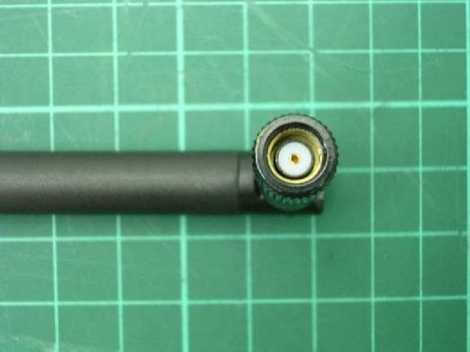
Click to zoom
Application Details
- Equipment Class
- DTS - Digital Transmission System
- Date of Grant
- Aug 18, 2004
- Application Purpose
- Original Equipment
- Date of Application
- Aug 18, 2004
- Equipment Note
- Wireless VPN Router
- Frequency Range
- 2412.00000000 - 2462.00000000
- Company
- Abocom Systems Inc
- Country
- Taiwan
Documents & Files
Document Text
Text extracted from the exhibit documents filed with the FCC. Open a document above to read the original.
Users Manual
Wireless VPN Router 802.11g/802.11b Wireless Access Point Broadband Internet Access 4-Port Switching Hub User’s Manual i Table of Contents CHAPTER 1 INTRODUCTION.............................................................................1 Wireless VPN router Features......................................................................................1 Package Contents..........................................................................................................1 Physical Details.............................................................................................................2 CHAPTER 2 INSTALLATION..............................................................................4 Requirements................................................................................................................4 Procedure......................................................................................................................4 CHAPTER 3 CONFIGURATION..........................................................................6 Setup Wizard................................................................................................................7 Check the Network Connection....................................................................................9 CHAPTER 4 CONFIGURATION VIA WEB.........................................................................................10 Internet Port...............................................................................................................10 Local Port....................................................................................................................15 Advanced Setup..........................................................................................................17 Network Status............................................................................................................25 Others.........................................................................................................................26 1 Chapter 1 Introduction Congratulations on the purchase of your new Wireless Router. The Wireless VPN router is a multi-function device providing the following services: • Shared Broadband Internet Access for all LAN users. • 4-Port Switching Hub for 10BaseT or 100BaseT connections. • Wireless Access Point for 802.11b and 802.11g Wireless Stations. Figure 1: Wireless VPN Router Application Map Wireless VPN router Features The Wireless VPN router incorporates many advanced features, carefully designed to provide sophisticated functions while being easy to use. Package Contents The following items should be included: • The Wireless VPN router Unit • Power Adapter • Quick Installation Guide • CD-ROM containing the on-line manual. If any of the above items are damaged or missing, please contact your dealer immediately. 1 2 Physical Details Front-mounted LEDs Figure 2: Front Panel Color Status Pwr/Er r Green On - Power on. Off - No power. WAN Green On - Connection to the Broadband Modem attached to the WAN port is established. Off - No connection to the Broadband Modem. Flashing - Data is being transmitted or received via the WAN port. WLAN Green On - Wireless connection available; Wireless Access Point is ready for use. Off - No Wireless connection available. Flashing - Data is being transmitted or received via the Wireless access point. Data includes "network traffic" as well as user data. LAN (1-4) Green On -Linked to LAN Off - No link to LAN Flashing - Data is being transmitted or received via LAN DMZ Green On -Linked to DMZ Off - No link to DMZ Flashing - Data is being transmitted or received via DMZ Rear Panel Figure 3: Rear Panel 3 Power port (DC 5V) Connect the supplied power adapter here. 10/100BaseT LAN port Use standard LAN cables (RJ45 connectors) to connect your PCs to these ports. If required, any port can be connected to another hub. Any LAN port will automatically function as an "Uplink" port when necessary. WAN port (10/100BaseT) Connect the DSL or Cable Modem here. If your modem came with a cable, use the supplied cable. Otherwise, use a standard LAN cable. Reset Button 4 Chapter 2 Installation Requirements • Network cables. Use standard 10/100BaseT network (UTP) cables with RJ45 connectors. • TCP/IP protocol must be installed on all PCs. • For Internet Access, an Internet Access account with an ISP, and either of a DSL or Cable modem (for WAN port usage) • To use the Wireless Access Point, all Wireless devices must be compliant with the IEEE802.11b or IEEE802.11g specifications. Procedure Figure 4: Installation Diagram 1. Choose an Installation Site Select a suitable place on the network to install the Wireless Router. Ensure the Wireless VPN router and the DSL/Cable modem are powered OFF. 2. Connect LAN Cables Connect PCs to the LAN ports on the Wireless VPN router with standard LAN cables (RJ-45). 3. Connect WAN Cable Connect the DSL or Cable modem to the WAN port on the Wireless Router. Use the cable supplied with your DSL/Cable modem. If no cable was supplied, use a standard cable. 4. Power Up • Power on the Cable or DSL modem. • Connect the supplied power adapter to the Wireless VPN router and power up. Use only the power adapter provided. Using a different one may cause hardware damage 2 5 5. Check the LEDs • The Power LED should be ON. • For each LAN (PC) connection, the LAN should be ON (provided the PC is also ON.) • The WAN LED should be ON. • The WLAN LED should be ON 6 NOTE ! Chapter 3 Configuration Before setting up the Wireless Router, make sure your PCs are configured to "Obtain an IP (or TCP/IP) address automatically". For Windows 2000 & XP Users 1. Go to Start ‡ Control Panel‡ Network and Internet Connections‡ (Right-click on) Local Area Connection‡ Properties 2. Make sure the box next to Internet Protocol (TCP/IP) is checked. Click the Internet Protocol (TCP/IP) and click the Properties button. 3. Select "Obtain an IP address automatic…
Text truncated - open the document above for the full version.
Cover Letter(s)
American Telecommunications Certification Body Inc. 6731 Whittier Ave, McLean, VA 22101 August 17, 2004 RE: FCC ID: MQ4WR404_ATCB001599 Attention: Jerry Liu I have a few comments on this Application. Please note that further comments may arise in response to answers provided to the questions below. 1. Please note that the test report states that the removable antenna is an reverse SMA. However, it is not clear from the external photos if the antenna connector is a reverse SMA or a standard SMA. Please clarify and provide evidence that the external antenna is a reverse SMA connector (i.e. clearer photo of the connector). 2. Please note that the data tables starting on page 22 through 27 are in error. For example, plese note that the column labeled margin contains numbers in the hundreds of dB; the corrected reading column appears to be what should be the limit column; and the reading column appears to be what should be the corrected reading column. Please correct the data tables to reflect the actual numbers applicable to the column. 3. Please note that the band edge plots for the radiated band edge readings on pages 42, 44 and 46 show that the analyzer may be being overdriven by the signal. This consequently may cause erroneous readings. Please provide these plots under a condition where the analyzer is not being overdriven. Dennis Ward mailto:[email protected] The items indicated above must be submitted before processing can continue on the above referenced application. Failure to provide the requested information may result in application termination. Correspondence should be considered part of the permanent submission and may be viewed from the Internet after a Grant of Equipment Authorization is issued. Please do not respond to this correspondence using the email reply button. In order for your response to be processed expeditiously, you must submit your documents through the AmericanTCB.com website. Also, please note that partial responses increase processing time and should not be submitted. Any questions about the content of this correspondence should be directed to the sender.
External Photos
Photo 1: External photo of EUT WR404 Photo 2: External photo of EUT WR404 Photo 3: External photo of EUT WR404 Photo 3: External photo of EUT WR404
External Photos
Photo 1: External photo of EUT Antenna Connector Type: SMA (Reverse) WR404
ID Label/Location Info
802.11g Wireless VPN Router This device complies with Part 15 of the FCC Rules. Operation is subject to the following two conditions: (1) this device may not cause harmful interference, and (2) this device must accept any interference received, including interference that may cause undesired operation. FCC ID: MQ4WR404 Label location Tested To Comply With FCC Standards 0560 Rating:5V DC 2.4A Made In Taiwan 40.0mm 38.0mm 2 5 . 5 m m 2 8 . 5 m m
Internal Photos
Photo 1: Internal photo of EUT WR404 Photo 2: Internal photo of EUT WR404 Photo 3: Internal photo of EUT WR404 Photo 4: Internal photo of EUT WR404 Photo 5: Internal photo of EUT WR404
RF Exposure Info
FCC ID. : MQ4WR404 Report No.: EME-040603 Page 1 of 5 Clay Chen Maximum Permissible Exposure (MPE) Evaluation Report Report No. : EME-040603 Model No. : WR404 Issued Date : Aug. 4, 2004 Applicant : AboCom Systems, Inc. 1F, No. 21, Yanfa 2 nd Rd., SBIP, HsinChu City 300, Taiwan Test By : Intertek Testing Services Taiwan Ltd. No. 11, Lane 275, Ko-Nan 1 Street, Chia-Tung Li, Shiang-Shan District, Hsinchu City, Taiwan This test report consists of 5 pages in total. It may be duplicated completely for legal use with the allowance of the applicant. It shall not be reproduced except in full, without the written approval of Intertek Laboratory. The test result in this report only applies to the tested sample. Project Engineer Reviewed By Jerry Liu FCC ID. : MQ4WR404 Report No.: EME-040603 Page 2 of 5 Table of Contents Summary of Tests.........................................................................................................3 1. Introduction..............................................................................................................4 2. RF Exposure Limit....................................................................................................4 3. RF Exposure calculations..........................................................................................5 4. Test results................................................................................................................5 FCC ID. : MQ4WR404 Report No.: EME-040603 Page 3 of 5 Summary of Tests MPE Evaluation meet FCC OET No. 65: 1997/ IEEE C95.1-1999 802.11g Wireless VPN Router -Model: WR404 FCC ID: MQ4WR404 Test Reference Results MPE Evaluation FCC Guidelines for Human Exposure IEEE C95.1 Complies FCC ID. : MQ4WR404 Report No.: EME-040603 Page 4 of 5 1. Introduction The EUT operates in the 2.4GHz ISM band. Due to the EUT (include antenna) at its normal operation distance is at least 20 cm from the human body, the EUT was defined as a Mobile Device. The reason to do the MPE Evaluation is to avoid the RF hazard to human body. The maximum output power and gain of the antenna were used to calculate the limited Power density (S) at 20cm distance away from the product. The limit for Maximum Permissible Exposure (MPE) specified in FCC 1.1310 is followed. 2. RF Exposure Limit According to FCC 1.1310: The criteria listed in the following table shall be used to evaluate the environmental impact of human exposure to radio-frequency (RF) radiation as specified in 1.1307(b). Limits for Maximum Permissible Exposure (MPE) Frequency Range (MHz) Electric Field Strength (V/m) Magnetic Field Strength (A/m) Power Density (mW/cm 2 ) Average Time (minutes) (A) Limits for Occupational / Control Exposures 30-300 61.4 0.163 1.0 6 300-1500 - - F/300 6 1500-100,000 - - 5 6 (B) Limits for General Population / Uncontrolled Exposure 30-300 27.5 0.073 0.2 30 300-1500 - - F/1500 30 1500-100,000 - - 1.0 30 F= Frequency in MHz FCC ID. : MQ4WR404 Report No.: EME-040603 Page 5 of 5 3. RF Exposure calculations From § FCC 1.1310 table 1, the maximum permissible RF exposure for an uncontrolled environment is 1mW/(cm 2 ) Power density (S) is calculated by the following formula: S = (P * G)/4πR 2 where, S = Power density (mW/cm 2 ) P = Output power to antenna (mW) R = Distance between radiating structure and observation point (cm) G = Gain of antenna in numeric π = 3.1416 Example: Assume a mobile device operates at 2412MHz and its maximum output power is 50mW, and the maximum gain of antenna is 1 (numeric) /0dBi. then the power density (S) = (50 * 1)/4*π*20 2 = 0.00995 (mW/cm 2 ) 4. Test results Test Mode: 802.11b operation mode (DSSS Modulation) Channel Channel Frequency (MHz) Maximum antenna gain (numeric) Output power to antenna (mW) Power density (mW/cm 2 ) Limit of power density (mW/cm 2 ) 1 2412 1.58 130.62 0.0412 1.0 6 2437 1.58 118.85 0.0375 1.0 11 2462 1.58 123.88 0.0391 1.0 Test Mode: 802.11g operation mode (OFDM Modulation) Channel Channel Frequency (MHz) Maximum antenna gain (numeric) Output power to antenna (mW) Power density (mW/cm 2 ) Limit of power density (mW/cm 2 ) 1 2412 1.58 118.03 0.0372 1.0 6 2437 1.58 104.23 0.0329 1.0 11 2462 1.58 111.43 0.0351 1.0 The Notice in Installation Manual has been stated as below: While installing and operating this transmitter, the radio frequency exposure limit of 1mW/(cm*cm) may be exceeded at distances close to the transmitter. therefore, the user must maintain a minimum distance of 20 cm from the device at all time.
Test Report
FCC ID. : MQ4WR404 Report No.: EME-040603 Page 1 of 51 EMC TEST REPORT Report No. : EME-040603 Model No. : WR404 Issued Date : Aug. 4, 2004 Applicant : AboCom Systems, Inc. 1F, No. 21, Yanfa 2 nd Rd., SBIP, HsinChu City 300, Taiwan Test By : Intertek Testing Services Taiwan Ltd. No. 11, Lane 275, Ko-Nan 1 Street, Chia-Tung Li, Shiang-Shan District, Hsinchu City, Taiwan This test report consists of 51 pages in total. It may be duplicated completely for legal use with the allowance of the applicant. It shall not be reproduced except in full, without the written approval of Intertek Laboratory. The test result(s) in this report only applies to the tested sample(s). Clay Chen Project Engineer Reviewed By Jerry Liu FCC ID. : MQ4WR404 Report No.: EME-040603 Page 2 of 51 Table of Contents Summary of Tests.........................................................................................................4 1. General information.................................................................................................5 1.1 Identification of the EUT...................................................................................5 1.2 Additional information about the EUT...............................................................5 1.3 Antenna description...........................................................................................6 1.4 Peripherals equipment........................................................................................6 2. Test specifications....................................................................................................7 2.1 Test standard......................................................................................................7 2.2 Operation mode.................................................................................................7 2.3 Test equipment...................................................................................................8 3. Minimum 6dB Bandwidth test..................................................................................9 3.1 Operating environment.......................................................................................9 3.2 Test setup & procedure.......................................................................................9 3.3 Measured data of Minimum 6dB Bandwidth test results.....................................9 4. Maximum Output Power test...................................................................................16 4.1 Operating environment......................................................................................16 4.2 Test setup & procedure......................................................................................16 4.3 Measured data of Maximum Output Power test results......................................17 5. Radiated Emission test.............................................................................................18 5.1 Operating environment......................................................................................18 5.2 Test setup & procedure......................................................................................18 5.3 Emission limits.................................................................................................19 5.4 Radiated spurious emission test data.................................................................20 5.4.1 Measurement results: frequencies equal to or less than 1 GHz........................20 5.4.2 Measurement results: frequency above 1GHz.................................................22 6. Power Spectrum Density test...................................................................................28 6.1 Operating environment......................................................................................28 6.2 Test setup & procedure......................................................................................28 6.3 Measured data of Power Spectrum Density test results......................................28 7. Emission on the band edge §FCC 15.247(C)............................................................35 7.1 Band-edge (Conducted method)........................................................................36 7.2 Band-edge (Radiated method)...........................................................................40 FCC ID. : MQ4WR404 Report No.: EME-040603 Page 3 of 51 8. Power Line Conducted Emission test §FCC 15.207.................................................48 8.1 Operating environment......................................................................................48 8.2 Test setup & procedure......................................................................................48 8.3 Power Line Conducted Emission test data.........................................................50 FCC ID. : MQ4WR404 Report No.: EME-040603 Page 4 of 51 Summary of Tests 802.11g Wireless VPN Router -Model: WR404 FCC ID: MQ4WR404 Test Reference Results Minimum 6dB Bandwidth test 15.247(a)(2) Complies Maximum Output Power test 15.247(b) Complies Radiated Spurious Emission test 15.205, 15.209 Complies Power Spectrum Density test 15.247(d) Complies Power Line Conducted Emission test 15.207 Complies FCC ID. : MQ4WR404 Report No.: EME-040603 Page 5 of 51 1. General information 1.1 Identification of the EUT Applicant : AboCom Systems, Inc. Product : 802.11g Wireless VPN Router Model No. : WR404 FCC ID. : MQ4WR404 Frequency Range : 2400 MHz to 2483.5MHz Channel Number : 11 Channels Frequency of Each Channel : 2412MHz, 2417MHz, 2422MHz, 2427MHz, 2432MHz, 2437MHz, 2442MHz, 2447MHz, 2452MHz, 2457MHz, 2462MHz Type of Modulation : DSSS, OFDM Rated Power : 120Vac, 60Hz with Adapter Power Cord : N/A Sample Received : June 23, 2004 Test Date(s) : June 23, 2004 to July 30, 2004 1.2 Additional information about the EUT The 802.11g Wireless VPN Router is a multi-function device providing the following services: • Shared Broadband Inte…
Text truncated - open the document above for the full version.
Test Setup Photos
Photo 1: Conducted Emission Test Set-up Photo 2: Conducted Emission Test Set-up WR404 WR404
Test Setup Photos
Photo 1: Radiated Emission Test Set-up Photo 2: Radiated Emission Test Set-up WR404 WR404
Contact Information
Applicant
Harry Huang(Manager)
Technical Contact
Intertek Testing Services Taiwan Ltd.Jerry Liu
[email protected](+886)-3-519-1411
No. 11, Ko-Tze-Nan Chia-Tung Li, · Hsinchu · Taiwan
Test Firm
Intertek Testing Services Taiwan Ltd.Alpha Liu
Technical Specifications
| # | Rule Parts | Frequency Range | Power Output |
|---|---|---|---|
| 1 | 15C | 2.41 GHz - 2.46 GHz | 131.00 mW |
Other Applications from Abocom Systems Inc

MQ4WM5208
Oct 27, 2015802.11b/g/n Module
Equipment Class
DTS - Digital Transmission System
MQ4AM7221
Mar 18, 20152T2R 802.11b/g/n/ac Module
Equipment Class
DTS - Digital Transmission System
MQ4PLW72
Mar 18, 201511ac WiFi Extender Smart Plug / 11ac WiFi Extender
Equipment Class
NII - Unlicensed National Information Infrastructure TX
MQ4CB1522M
Sep 22, 2014IP Camera
Equipment Class
DTS - Digital Transmission System
MQ4-MBR-1100
Sep 21, 2014Android TV Dongle
Equipment Class
JBC - Part 15 Class B Computing Device/Personal Computer