MQ4WUG2400802.11g WLAN USB 2.0 Adapter
Abocom Systems Inc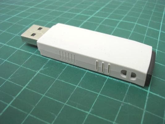
Click to zoom
Application Details
- Equipment Class
- DTS - Digital Transmission System
- Date of Grant
- Apr 11, 2005
- Application Purpose
- Original Equipment
- Date of Application
- Apr 11, 2005
- Equipment Note
- 802.11g WLAN USB 2.0 Adapter
- Frequency Range
- 2412.00000000 - 2462.00000000
- Company
- Abocom Systems Inc
- Country
- Taiwan
Documents & Files
Document Text
Text extracted from the exhibit documents filed with the FCC. Open a document above to read the original.
Users Manual
802.11b/g Wireless LAN USB2.0 Adapter User’s Manual REGULATORY STATEMENTS FCC Certification The United States Federal Communication Commission (FCC) and the Canadian Department of Communications have established certain rules governing the use of electronic equipment. The 802.11b/g Wireless LAN USB2.0 Adapter has been tested to the FCC exposure requirements (Specific Absorption Rate) measured value of 0.998 watts/kg Part15, Class B Warning: Changes or modifications to this unit not expressly approved by the party responsible for compliance could void the user authority to operate the equipment. This device complies with Part 15 of the FCC Rules. Operation is subject to the following two conditions: (1) this device may not cause harmful interference, and (2) this device must accept any interference received, including interference that may cause undesired operation. This equipment has been tested and found to comply with the limits for a Class B digital device, pursuant to Part 15 of the FCC Rules. These limits are designed to provide reasonable protection against harmful interference in a residential installation. This equipment generates, uses and can radiate radio frequency energy, and if not installed and used in accordance with the instructions, may cause harmful interference to radio communications. However, there is no guarantee that interference will not occur in a particular installation. If this equipment does cause harmful interference to radio or television reception, which can be determined by turning off and on, the user is encouraged to try to correct the interference by one or more of the following measures: Reorient or relocate the receiving antenna. Increase the distance between the equipment and receiver. Connect the equipment into an outlet on a circuit different from that to which the receiver is connected. CAUTION: This transmitter must not be co-located or operating in conjunction with any other antenna or transmitter. The equipment complies with FCC RF radiation exposure limits set forth for an uncontrolled environment, under 47 CFR 2.1093 paragraph (d)(2). Table of Contents INTRODUCTION .................................................................................................... 1 WIRELESS NETWORK OPTIONS................................................................................ 1 The Peer-to-Peer Network .......................................................................... 1 The Access Point Network ......................................................................... 2 LED INDICATORS FOR WIRELESS USB ADAPTER................................................... 2 Power Indicator: (Orange LED) ................................................................. 2 Act Indicator: (Green LED)........................................................................ 2 INSTALLATION...................................................................................................... 3 INSTALL THE DRIVER & UTILITY............................................................................. 3 INSTALL THE DEVICE................................................................................................ 6 Note for Windows 98 users: ....................................................................... 6 Note for Windows XP users: ...................................................................... 6 Verify Device Installation........................................................................... 7 NETWORK CONNECTION .................................................................................. 9 IN WINDOWS 98/ME ............................................................................................... 9 IN WINDOWS 2000/XP .......................................................................................... 12 CONFIGURATION................................................................................................ 15 ACCESSING THE CONFIGURATION UTILITY............................................................ 15 MAIN TAB............................................................................................................. 16 PROFILE MANAGER TAB........................................................................................ 25 INFORMATION TAB................................................................................................ 26 ABOUT TAB........................................................................................................... 28 UNINSTALLATION .............................................................................................. 29 - 1 - INTRODUCTION The 802.11b/g Wireless LAN USB2.0 Adapter is a device that allows you connect your computer to a wireless local area network (LAN). A wireless LAN allows your system to use wireless Radio Frequency (RF) technology to transmit and receive data without physically attaching to the network. The Wireless protocols that come with this product ensure data security and isolation from interference generated by other radio frequencies. This Adapter also allows you to take full advantage of your computer’s mobility with access to real-time information and online services anytime and anywhere. In addition, this device eliminates the bother of pulling cable through walls and under furniture. It even allows you to place your system in locations where cabling is impossible. Modifying and augmenting networks has never been so easy. Wireless Network Options The Peer-to-Peer Network This network installation lets you set a small wireless workgroup easily and quickly. Equipped with Wireless USB Adapter, you can share files and printers between each PC and laptop. - 2 - You can also use one computer as an Internet Server to connect to a wired global network and share files and information with other computers via a wireless LAN. The Access Point Network The network installation allows you to share files, printers, and Internet access much more convenientl…
Text truncated - open the document above for the full version.
External Photos
Photo 1: External photo of EUT WR254 Photo 2: External photo of EUT WR254
ID Label/Location Info
Label location 51mm 1 2 m m
Internal Photos
Photo 1: Internal photo of EUT WUG2400 Photo 2: Internal photo of EUT WUG2400 Photo 3: Internal photo of EUT WUG2400
RF Exposure Info
FCC ID. : MQ4WUG2400 Report No.: EME-050236 Page 1 of 79 0597 ILAC MRA Specific Absorption Rate (SAR) Test Report for AboCom Systems, Inc. on the 802.11b/g Wireless LAN USB2.0 Adapter Model Number: WUG2400 Test Report: EME-050236 Date of Report: Mar. 30, 2005 Date of test: Mar. 23, 2005 Total No of Pages Contained in this Report: 79 Accredited for testing to FCC Part 15 Tested by: Marx Yan Reviewed by: Jerry Liu Review Date: Mar. 30, 2005 All services undertaken are subject to the following general policy: Reports are submitted for exclusive use of the client to whom they are addressed. Their significance is subject to the adequacy and representative character of the samples and to the comprehensiveness of the tests, examinations or surveys made. This report shall not be reproduced except in full, without written consent of Intertek Testing Services, Taiwan Ltd. FCC ID. : MQ4WUG2400 Report No.: EME-050236 Page 2 of 79 Table of Contents 1.0 Job Description.......................................................................................................4 1.1 Client Information...............................................................................................4 1.2 Equipment under test (EUT)................................................................................4 1.3 Test plan reference...............................................................................................5 1.4 System test configuration.....................................................................................5 1.4.1 Support equipment & System block diagram....................................................5 1.4.2 Test Position.....................................................................................................6 1.4.3 Test Condition..................................................................................................6 1.5 Modifications required for compliance................................................................7 1.6 Additions, deviations and exclusions from standards............................................7 2.0 SAR Evaluation......................................................................................................8 2.1 SAR Limits.........................................................................................................8 2.2 Configuration Photographs..................................................................................9 2.3 SAR measurement system.................................................................................16 2.4 SAR measurement system validation.................................................................17 2.4.1 System Validation result.................................................................................18 2.4.2 System Performance Check result...................................................................20 2.5 Test Result.........................................................................................................22 3.0 Test Equipment.....................................................................................................24 3.1 Equipment List..................................................................................................24 3.2 Tissue Simulating Liquid...................................................................................25 3.2.1 Body Tissue Simulating Liquid for evaluation test..........................................25 3.2.2 Head Tissue Simulating Liquid for System performance Check test................25 3.2.3 Body Liquid results........................................................................................26 3.2.4 Head Liquid results.........................................................................................27 3.3 E-Field Probe and 2450 Balanced Dipole Antenna Calibration..........................28 4.0 Measurement Uncertainty.....................................................................................29 5.0 Measurement Traceability.....................................................................................31 6.0 WARNING LABEL INFORMATION - USA.......................................................31 7.0 REFERENCES.....................................................................................................32 8.0 DOCUMENT HISTORY......................................................................................33 APPENDIX A - SAR Evaluation Data........................................................................34 APPENDIX B - Photographs......................................................................................51 APPENDIX C - E-Field Probe and 2450MHz Balanced Dipole Antenna Calibration Data 52 FCC ID. : MQ4WUG2400 Report No.: EME-050236 Page 3 of 79 STATEMENT OF COMPLIANCE The AboCom sample device, model # WUG2400 was evaluated in accordance with the requirements for compliance testing defined in FCC OET Bulletin 65, Supplement C (Edition 01-01). Testing was performed at the Intertek Testing Services facility in Hsinchu, Taiwan. For the evaluation, the dosimetric assessment system INDEXSAR SARA2 was used. The phantom employed was the box phantom of 2mm thick in each wall. The total uncertainty for the evaluation of the spatial peak SAR values averaged over a cube of 1g tissue mass had been assessed for this system to be ± 20.6%. The device was tested at their maximum output power declared by the AboCom. In summary, the maximum spatial peak SAR value for the sample device averaged over 1g was found to be: Phantom Position (worst case) SAR 1g , W/kg 2mm thick box phantom wall 802.11b low channel EUT bottom to the phantom, 0 mm separation. 0.998 W/kg In conclusion, the tested Sample device was found to be in compliance with the requirements defined in OET Bulletin 65, Supplement C (Edition 01-01) for body configurations. FCC ID. : MQ4WUG2400 Report No.: EME-050236 Page 4 of 79 1.0 Job Description 1.1 Client Information The WUG2400 has been teste…
Text truncated - open the document above for the full version.
Test Report
FCC ID. : MQ4WUG2400 Report No.: EME-050235 Page 1 of 49 EMC TEST REPORT Report No. : EME-050235 Model No. : WUG2400 Issued Date : Mar. 30, 2005 Applicant : AboCom Systems, Inc. 1F, No. 21, Yanfa 2 nd Rd., SBIP, HsinChu City 300, Taiwan Test By : Intertek Testing Services Taiwan Ltd. No. 11, Lane 275, Ko-Nan 1 Street, Chia-Tung Li, Shiang-Shan District, Hsinchu City, Taiwan This test report consists of 49 pages in total. It may be duplicated completely for legal use with the allowance of the applicant. It shall not be reproduced except in full, without the written approval of Intertek Laboratory. The test result(s) in this report only applies to the tested sample(s). Victor Wen Project Engineer Reviewed By Jerry Liu FCC ID. : MQ4WUG2400 Report No.: EME-050235 Page 2 of 49 Table of Contents Summary of Tests..........................................................................................................4 1. General information..................................................................................................5 1.1 Identification of the EUT.....................................................................................5 1.2 Additional information about the EUT.................................................................5 1.3 Antenna description.............................................................................................6 1.4 Peripherals equipment..........................................................................................6 2. Test specifications.....................................................................................................7 2.1 Test standard........................................................................................................7 2.2 Operation mode...................................................................................................7 2.3 Test equipment.....................................................................................................8 3. Minimum 6dB Bandwidth test...................................................................................9 3.1 Operating environment........................................................................................9 3.2 Test setup & procedure........................................................................................9 3.3 Measured data of Minimum 6dB Bandwidth test results......................................9 4. Maximum Output Power test...................................................................................16 4.1 Operating environment......................................................................................16 4.2 Test setup & procedure......................................................................................16 4.3 Measured data of Maximum Output Power test results.......................................16 5. Radiated Emission test.............................................................................................17 5.1 Operating environment......................................................................................17 5.2 Test setup & procedure......................................................................................17 5.3 Emission limits..................................................................................................18 5.4 Radiated spurious emission test data..................................................................19 5.4.1 Measurement results: frequencies equal to or less than 1 GHz.........................19 5.4.2 Measurement results: frequency above 1GHz.................................................20 6. Power Spectrum Density test...................................................................................26 6.1 Operating environment......................................................................................26 6.2 Test setup & procedure......................................................................................26 6.3 Measured data of Power Spectrum Density test results.......................................26 7. Emission on the band edge §FCC 15.247(C)............................................................33 7.1 Band-edge (Conducted method).........................................................................34 7.2 Band-edge (Radiated method)............................................................................38 FCC ID. : MQ4WUG2400 Report No.: EME-050235 Page 3 of 49 8. Power Line Conducted Emission test §FCC 15.207.................................................46 8.1 Operating environment......................................................................................46 8.2 Test setup & procedure......................................................................................46 8.3 Emission limit...................................................................................................47 8.4 Uncertainty of Conducted Emission...................................................................47 8.5 Power Line Conducted Emission test data..........................................................48 FCC ID. : MQ4WUG2400 Report No.: EME-050235 Page 4 of 49 Summary of Tests 802.11b/g Wireless LAN USB2.0 Adapter-Model: WUG2400 FCC ID: MQ4WUG2400 Test Reference Results Minimum 6dB Bandwidth test 15.247(a)(2) Complies Maximum Output Power test 15.247(b) Complies Radiated Spurious Emission test 15.205, 15.209 Complies Power Spectrum Density test 15.247(d) Complies Power Line Conducted Emission test 15.207 Complies FCC ID. : MQ4WUG2400 Report No.: EME-050235 Page 5 of 49 1. General information 1.1 Identification of the EUT Applicant : AboCom Systems, Inc. Product : 802.11b/g Wireless LAN USB2.0 Adapter Model No. : WUG2400 FCC ID. : MQ4WUG2400 Frequency Range : 2400 MHz to 2483.5MHz Channel Number : 11 Channels Frequency of Each Channel : 2412MHz, 2417MHz, 2422MHz, 2427MHz, 2432MHz, 2437MHz, 2442MHz, 2447MHz, 2452MHz, 2457MHz, 2462MHz Type of Modulation : DSSS, …
Text truncated - open the document above for the full version.
Test Setup Photos
Photo 1: Conducted Emission Test Set-up WUG2400 Photo 2: Conducted Emission Test Set-up WUG2400
Test Setup Photos
Photo 1: Radiated Emission Test Set-up WUG2400 Photo 2: Radiated Emission Test Set-up WR254
Contact Information
Applicant
Harry Huang(Manager)
Technical Contact
Intertek Testing Services Taiwan Ltd.Jerry Liu
[email protected]+886 3 519 1411
11, Lane 275, Ko Nan 1st St. · Hsinchu · Taiwan
Test Firm
Intertek Testing Services Taiwan Ltd.Alpha Liu
Technical Specifications
| # | Rule Parts | Frequency Range | Power Output |
|---|---|---|---|
| 1 | 15C | 2.41 GHz - 2.46 GHz | 40.30 mW |
Other Applications from Abocom Systems Inc

MQ4WM5208
Oct 27, 2015802.11b/g/n Module
Equipment Class
DTS - Digital Transmission System
MQ4AM7221
Mar 18, 20152T2R 802.11b/g/n/ac Module
Equipment Class
DTS - Digital Transmission System
MQ4PLW72
Mar 18, 201511ac WiFi Extender Smart Plug / 11ac WiFi Extender
Equipment Class
NII - Unlicensed National Information Infrastructure TX
MQ4CB1522M
Sep 22, 2014IP Camera
Equipment Class
DTS - Digital Transmission System
MQ4-MBR-1100
Sep 21, 2014Android TV Dongle
Equipment Class
JBC - Part 15 Class B Computing Device/Personal Computer