MQ4WUG2700802.11b/g Mini Wireless LAN USB 2.0 Adapter
Abocom Systems Inc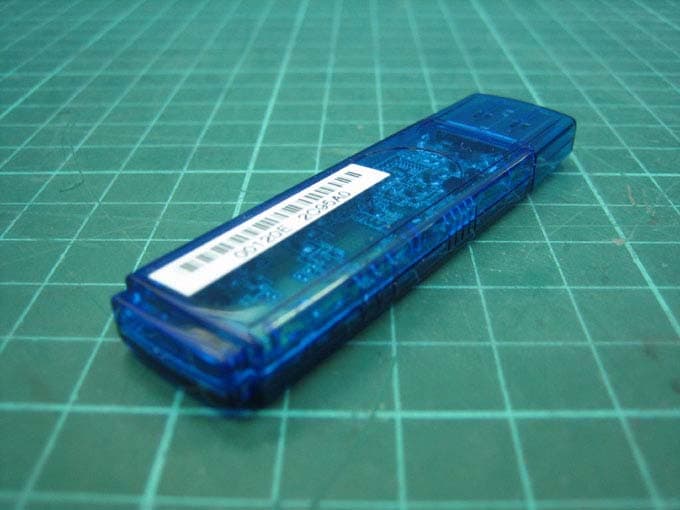
Click to zoom
Application Details
- Equipment Class
- DTS - Digital Transmission System
- Date of Grant
- Mar 08, 2006
- Application Purpose
- Original Equipment
- Date of Application
- Mar 07, 2006
- Equipment Note
- 802.11b/g Mini Wireless LAN USB 2.0 Adapter
- Frequency Range
- 2412.00000000 - 2462.00000000
- Company
- Abocom Systems Inc
- Country
- Taiwan
Documents & Files
Document Text
Text extracted from the exhibit documents filed with the FCC. Open a document above to read the original.
Users Manual
802.11b/g USB Wireless LAN Card User’s Manual REGULATORY STATEMENTS FCC Certification The United States Federal Communication Commission (FCC) and the Canadian Department of Communications have established certain rules governing the use of electronic equipment. ※ The 802.11b/g USB Wireless LAN Card has been tested to the FCC exposure requirements (Specific Absorption Rate) measured value of 0.076 watts/kg. Part15, Class B Warning: Changes or modifications to this unit not expressly approved by the party responsible for compliance could void the user authority to operate the equipment. This device complies with Part 15 of the FCC Rules. Operation is subject to the following two conditions: (1) this device may not cause harmful interference, and (2) this device must accept any interference received, including interference that may cause undesired operation. This equipment has been tested and found to comply with the limits for a Class B digital device, pursuant to Part 15 of the FCC Rules. These limits are designed to provide reasonable protection against harmful interference in a residential installation. This equipment generates, uses and can radiate radio frequency energy, and if not installed and used in accordance with the instructions, may cause harmful interference to radio communications. However, there is no guarantee that interference will not occur in a particular installation. If this equipment does cause harmful interference to radio or television reception, which can be determined by turning off and on, the user is encouraged to try to correct the interference by one or more of the following measures: ※ Reorient or relocate the receiving antenna. ※ Increase the distance between the equipment and receiver. ※ Connect the equipment into an outlet on a circuit different from that to which the receiver is connected. CAUTION: This transmitter must not be co-located or operating in conjunction with any other antenna or transmitter. The equipment complies with FCC RF radiation exposure limits set forth for an uncontrolled environment, under 47 CFR 2.1093 paragraph (d)(2). If you have any troble with use this equipment, please contact customer care service: Company Name: Xterasys Corporation Address: 4711 CHINO AVE. CHINO, CA91710 USA Tel: 909-590-0600 / Fax: 909-590-0388 Contact Person: Mr. Larry Table of Contents INTRODUCTION ...................................................................................................1 FEATURES..............................................................................................................1 SOFTWARE INSTALLATION .............................................................................2 INSTALL THE DRIVER & UTILITY............................................................................2 HARDWARE INSTALLATION............................................................................5 NETWORK CONNECTION .................................................................................7 IN WINDOWS 98SE/ME..........................................................................................7 IN WINDOWS 2000/XP .........................................................................................10 IP ADDRESS.........................................................................................................12 Configuration Utility .............................................................................................13 PROFILE...............................................................................................................14 LINK STATUS........................................................................................................15 SITE SURVEY........................................................................................................16 STATISTICS...........................................................................................................17 ADVANCED..........................................................................................................19 ABOUT.................................................................................................................20 UNINSTALLATION.............................................................................................21 - 1 - INTRODUCTION The 802.11b+g Wireless LAN USB Adapter is designed for a USB type A port of a laptop or desktop computer for creating a wireless workstation . It is USB 2.0 compliant which connects to any available USB port on a notebook or desktop computer. The 802.11b+g Wireless LAN USB Adapter complies with IEEE 802.11g standard that offers a data rate up to 54Mbps in a wireless LAN environment. It is backward compliant with IEEE 802.11b specification. The high-speed wireless network card can plug into your notebook or desktop PC and accesses to the LAN or peer-to-peer networking easily without wires or cables. Whether you’re at your desk or in the boardroom, it allows you to share printers, files, and other network resources. Features ¾ Complies with IEEE 802.11g standard for 2.4GHz Wireless LAN ¾ USB 2.0 compliant ¾ USB Plug & Play ¾ Interoperable with existing network infrastructure ¾ Secure information transmission ¾ Freedom to roam while staying connected ¾ Compatible with specialty wireless products and services ¾ Up to 54 Mbps data rate ¾ Antenna is built in the card with LED indication ¾ Low power consumption ¾ Easy to install and configure - 2 - SOFTWARE INSTALLATION Install the Driver & Utility Caution! Do not insert the wireless LAN adapter into your computer until the procedures in “ Install the Driver& Utility” have been performed. 1. Exit all Windows programs. Insert the included CD-ROM into your computer. The CD-ROM will run automatically. 2. When the Main Menu screen appears, click “ Driver & Utility Installation” to continue. 3. When the License Agreement screen appears, please read the contents and then click Yes to continue. 4. Select the check box to choose a c…
Text truncated - open the document above for the full version.
Cover Letter(s)
AboCom Systems, Inc. Head Office: 1F, No. 21, R&D Rd. II, SBIP, Hsin-Chu 300, Taiwan, R.O.C. Factory: No. 77, Yu-Yih Rd., Chu-Nan Chen, Miao-Lih Hsian 350, Taiwan, R.O.C. Mobile Interconnected Products: 8F, No. 123, Lane 235, Bao-Chiao Rd, Hsin-Tien City, Taipei 231, Taiwan, R.O.C. Power of Attorney "I, an officer of AboCom Systems, Inc. do hereby authorize Intertek Testing Services to act on our behalf in front of the Federal Communications Commission with respect to all matters relating to certification of equipment under Part 15 and Part 18 of the FCC Rules until further notice." I further certify that no party (as defined in §1.2002(b) of CFR 47, 1992) to this application, including myself, is subject to a denial of federal benefits, that includes FCC benefits, pursuant to Section 5301 of the Anti-Drug Abuse Act of 1988, 21 U.S.C.,853(a). By Ken Yang Signature Printed Title Project Manager
External Photos
Photo 1: External photo of EUT WUG2700 Photo 2: External photo of EUT WUG2700 Photo 3: External photo of EUT WUG2700 Photo 4: External photo of EUT WUG2700
ID Label/Location Info
35mm 15mm FCC ID Label Location
Internal Photos
Photo 1: Internal photo of EUT WUG2700 Photo 2: Internal photo of EUT WUG2700 Photo 3: Internal photo of EUT WUG2700 Photo 4: Internal photo of EUT WUG2700
RF Exposure Info
FCC ID. : MQ4WUG2700 Report No.: EME-060154 Page 1 of 68 Specific Absorption Rate (SAR) Test Report for AboCom Systems, Inc. on the 802.11b/g wireless USB dongle Model Number: WUG2700 Test Report: EME-060154 Issue date: Mar. 7, 2006 Total No of Pages Contained in this Report: 68 Accredited for testing to FCC Part 15 Tested by: Kevin Chen Reviewed by: Jerry Liu Review Date: Mar. 7, 2006 All services undertaken are subject to the following general policy: Reports are submitted for exclusive use of the client to whom they are addressed. Their significance is subject to the adequacy and representative character of the samples and to the comprehensiveness of the tests, examinations or surveys made. This report shall not be reproduced except in full, without written consent of Intertek Testing Services, Taiwan Ltd. 0597 FCC ID. : MQ4WUG2700 Report No.: EME-060154 Page 2 of 68 Table of Contents 1.0 General information .................................................................................................... 3 1.1 Client Information....................................................................................................... 3 1.2 Equipment under test (EUT) ....................................................................................... 4 1.3 Test plan reference ...................................................................................................... 4 1.4 Test configuration ....................................................................................................... 5 1.4.1 Support equipment & EUT antenna position ....................................................... 5 1.4.2 Test Condition ...................................................................................................... 6 1.5 Modifications required for compliance....................................................................... 6 2.0 SAR Evaluation........................................................................................................... 7 2.1 SAR Limits .................................................................................................................7 2.2 Configuration Photographs ......................................................................................... 8 2.3 SAR measurement system ........................................................................................ 12 2.4 SAR measurement system validation ....................................................................... 13 2.4.1 System Validation result ..................................................................................... 14 2.4.2 System Performance Check result...................................................................... 16 2.5 Test Result................................................................................................................. 18 3.0 Test Equipment ......................................................................................................... 19 3.1 Equipment List .......................................................................................................... 19 3.2 Tissue Simulating Liquid .......................................................................................... 20 3.2.1 Body Tissue Simulating Liquid for evaluation test ............................................ 20 3.2.2 Head Tissue Simulating Liquid for System performance Check test................. 20 3.2.3 Body Liquid results ............................................................................................ 21 3.2.4 Head Liquid results ............................................................................................ 22 3.3 E-Field Probe and 2450 Balanced Dipole Antenna Calibration ............................... 23 4.0 Measurement Uncertainty ......................................................................................... 24 5.0 WARNING LABEL INFORMATION - USA ......................................................... 26 6.0 REFERENCES.......................................................................................................... 27 7.0 Document Revision Record ...................................................................................... 28 APPENDIX A - SAR Evaluation Data ........................................................................... 29 APPENDIX B - Photographs .......................................................................................... 42 APPENDIX C - E-Field Probe and 2450MHz Balanced Dipole Antenna Calibration Data 46 FCC ID. : MQ4WUG2700 Report No.: EME-060154 Page 3 of 68 1.0 General information The device was tested at the Intertek Testing Services facility in Hsinchu, Taiwan. The maximum output power declared by the AboCom. EUT model # WUG2700 was evaluated accordance with the requirements for compliance testing defined in FCC OET Bulletin 65, Supplement C (Edition 01-01) and meet the SAR requirement, the phantom employed was the box phantom of 2mm thick in one wall. The total uncertainty for the evaluation of the spatial peak SAR values averaged over a cube of 1g tissue mass had been assessed for this system to be ±20.6%, the dosimetry assessment system INDEXSAR SARA2 was used. In summary, the maximum spatial peak SAR value for the sample device averaged over 1g was found to be: Phantom Position (worst case) SAR 1g , W/kg 2mm thick box phantom wall EUT perpendicular to the phantom, 0 mm separation. 0.076 W/kg In conclusion, the tested Sample device was found to be in compliance with the requirements defined in OET Bulletin 65, Supplement C (Edition 01-01) for body configurations. 1.1 Client Information The WUG2700 has been tested at the request of: Applicant: AboCom Systems, Inc. 1F, No. 21, Yanfa 2 nd Rd., SBIP, HsinChu City 300, Taiwan FCC ID. : MQ4WUG2700 Report No.: EME-060154 Page 4 of 68 1.2 Equipment under test (EUT) Product Descriptions: For marketing purpose, the EUT is designed to be with two types of enclosure. The worst case w…
Text truncated - open the document above for the full version.
RF Exposure Info
FCC ID. : MQ4WUG2700 Report No.: EME-060154 Page 41 of 68 Plot #6 (2/2) AREA SCAN: Min MaxSteps Y -30.030.0 6.0 Scan Extent: Z -175.0-135.04.0 FCC ID. : MQ4WUG2700 Report No.: EME-060154 Page 42 of 68 APPENDIX B - Photographs FCC ID. : MQ4WUG2700 Report No.: EME-060154 Page 43 of 68 FCC ID. : MQ4WUG2700 Report No.: EME-060154 Page 44 of 68 FCC ID. : MQ4WUG2700 Report No.: EME-060154 Page 45 of 68 FCC ID. : MQ4WUG2700 Report No.: EME-060154 Page 46 of 68 APPENDIX C - E-Field Probe and 2450MHz Balanced Dipole Antenna Calibration Data FCC ID. : MQ4WUG2700 Report No.: EME-060154 Page 47 of 68 IMMERSIBLE SAR PROBE CALIBRATION REPORT Part Number: IXP – 050 S/N 0114 March 2005 Indexsar Limited Oakfield House Cudworth Lane Newdigate Surrey RH5 5BG Tel: +44 (0) 1306 632 870 Fax: +44 (0) 1306 631 834 e-mail: [email protected] FCC ID. : MQ4WUG2700 Report No.: EME-060154 Page 48 of 68 INTRODUCTION This Report presents measured calibration data for a particular Indexsar SAR probe (S/N 0114) and describes the procedures used for characterisation and calibration. Indexsar probes are characterised using procedures that, where applicable, follow the recommendations of CENELEC [1] and IEEE [2] standards. The procedures incorporate techniques for probe linearisation, isotropy assessment and determination of liquid factors (conversion factors). Calibrations are determined by comparing probe readings with analytical computations in canonical test geometries (waveguides) using normalized power inputs. Each step of the calibration procedure and the equipment used is described in the sections below. CALIBRATION PROCEDURE 1. Objectives The calibration process comprises the following stages 1) Determination of the channel sensitivity factors which optimise the probe’s overall rotational isotropy in 1800MHz brain fluid 2) At each frequency of interest, application of these channel sensitivity factors to model the exponential decay of SAR in a sensitivity factors to model the exponential decay of SAR in a at that frequency 3) Determination of the effective tip radius and angular offset of the X channel which together optimise the probe’s spherical isotropy in 900MHz brain fluid 4) If requested by the Customer, determination of the probe’s response to GSM pulsed modulation 2. Probe output The probe channel output signals are linearised in the manner set out in Refs [1] and [2]. The following equation is utilized for each channel: where U lin is the linearised signal, U o/p is the raw output signal in voltage units and DCP is the diode compression potential in similar voltage units. DCP is determined from fitting equation (1) to measurements of U lin versus source feed power over the full dynamic range of the probe. The DCP is a characteristic of the Schottky diodes used as the sensors. For the IXP-050 probes with CW signals the DCP values are typically 0.10V (or 20 in the voltage units used by Indexsar software, which are V*200). In turn, measurements of E-field are determined using the following equation (where output voltages are also in units of V*200): FCC ID. : MQ4WUG2700 Report No.: EME-060154 Page 49 of 68 E liq 2 (V/m) = U linx * Air Factor x * Liq Factor x + U liny * Air Factor y * Liq Factor y + U linz * Air Factor z * Liq Factor z (3) Here, “Air Factor” represents each channel’s sensitivity, while “Liq Factor” represents the enhancement in signal level when the probe is immersed in tissue-simulant liquids at each frequency of interest. 3. Selecting channel sensitivity factors to optimise isotropic response After manufacture, the first stage of the calibration process is to balance the three channels’ Air Factor values, thereby optimising the probe’s overall axial response (“rotational isotropy”). To do this, an 1800MHz waveguide containing head-fluid simulant is selected. Like all waveguides used during probe calibration, this particular waveguide contains two distinct sections: an air-filled launcher section, and a liquid cell section, separated by a dielectric matching window designed to minimize reflections at the air-liquid interface. The waveguide stands in an upright position and the liquid cell section is filled with 1800MHz brain fluid to within 10 mm of the open end. The depth of liquid ensures there is negligible radiation from the waveguide open top and that the probe calibration is not influenced by reflections from nearby objects. During the measurement, a TE 01 mode is launched into the waveguide by means of an N-type-to- waveguide adapter. The probe is then lowered vertically into the liquid until the tip is exactly 10mm above the centre of the dielectric window. This particular separation ensures that the probe is operating in a part of the waveguide where boundary corrections are not necessary. Care must also be taken that the probe tip is centred while rotating. The exact power applied to the input of the waveguide during this stage of the probe calibration is immaterial since only relative values are of interest while the probe rotates. However, the power must be sufficiently above the noise floor and free from drift. The dedicated Indexsar calibration software rotates the probe in 10 degree steps about its axis, and at each position, an Indexsar ‘Fast’ amplifier samples the probe channels 500 times per second for 0.4 s. The raw U o/p data from each sample are packed into 10 bytes and transmitted back to the PC controller via an optical cable. U linx , U liny and U linz are derived from the raw U o/p values and written to an Excel template. Once data have been collected from a full probe rotation, the Air Factors are adjusted using a special Excel Solver routine to equalise the output from each channel and hence minimise the rotational isotropy. This automated approach to optimisation removes the effect of human bias. FCC ID. : MQ4WUG2700 Report No.: EME-060154 Page 50 of 68 Figure 5 represents the output from each diode sensor as a function of probe rotation angle. The directional…
Text truncated - open the document above for the full version.
Test Report
FCC ID. : MQ4WUG2700 Report No.: EME-060153 Page 1 of 47 EMC TEST REPORT Report No. : EME-060153 Model No. : WUG2700 Issued Date : Mar. 7, 2006 Applicant : AboCom Systems, Inc. 1F, No. 21, Yanfa 2 nd Road, SBIP, Hsinchu City 300, Taiwan Test By : Intertek Testing Services Taiwan Ltd. No. 11, Lane 275, Ko-Nan 1 Street, Chia-Tung Li, Shiang-Shan District, Hsinchu City, Taiwan This test report consists of 47 pages in total. It may be duplicated completely for legal use with the allowance of the applicant. It shall not be reproduced except in full, without the written approval of Intertek Laboratory. The test result(s) in this report only applies to the tested sample(s). Kevin Chen Project Engineer Reviewed By Jerry Liu FCC ID. : MQ4WUG2700 Report No.: EME-060153 Page 2 of 47 Table of Contents Summary of Tests ..............................................................................................................4 1. General information ......................................................................................................5 1.1 Identification of the EUT ........................................................................................5 1.2 Additional information about the EUT....................................................................5 1.3 Antenna description.................................................................................................6 1.4 Peripherals equipment .............................................................................................6 2. Test specifications .........................................................................................................7 2.1 Test standard............................................................................................................7 2.2 Operation mode .......................................................................................................7 2.3 Test equipment ........................................................................................................8 3. Minimum 6dB Bandwidth test ......................................................................................9 3.1 Operating environment............................................................................................9 3.2 Test setup & procedure ............................................................................................9 3.3 Measured data of Minimum 6dB Bandwidth test results ........................................9 4. Maximum Output Power test ......................................................................................16 4.1 Operating environment..........................................................................................16 4.2 Test setup & procedure ..........................................................................................16 4.3 Measured data of Maximum Output Power test results ........................................16 5. Radiated Emission test ................................................................................................17 5.1 Operating environment..........................................................................................17 5.2 Test setup & procedure ..........................................................................................17 5.3 Emission limits ......................................................................................................18 5.4 Radiated spurious emission test data.....................................................................19 5.4.1 Measurement results: frequencies equal to or less than 1 GHz..........................19 5.4.2 Measurement results: frequency above 1GHz ...................................................20 6. Power Spectrum Density test ......................................................................................26 6.1 Operating environment..........................................................................................26 6.2 Test setup & procedure ..........................................................................................26 6.3 Measured data of Power Spectrum Density test results ........................................26 7. Emission on the band edge..........................................................................................33 7.1 Operating environment..........................................................................................33 7.2 Test setup & procedure ..........................................................................................33 7.3 Test Result .............................................................................................................34 FCC ID. : MQ4WUG2700 Report No.: EME-060153 Page 3 of 47 7.3.1 Conducted Method .............................................................................................34 7.3.2 Radiated Method ................................................................................................42 8. Power Line Conducted Emission test §FCC 15.207 ...................................................44 8.1 Operating environment..........................................................................................44 8.2 Test setup & procedure ..........................................................................................44 8.3 Emission limit .......................................................................................................45 8.4 Uncertainty of Conducted Emission .....................................................................45 8.5 Power Line Conducted Emission test data ............................................................46 FCC ID. : MQ4WUG2700 Report No.: EME-060153 Page 4 of 47 Summary of Tests 802.11b/g wireless USB dongle-Model: WUG2700 FCC ID: MQ4WUG2700 Test Reference Results Minimum 6dB Bandwidth test 15.247(a)(2) Complies Maximum Output Power test 15.247(b) Complies Radiated Spurious Emission test 15.205, 15.209 Complies Power Spectrum Densi…
Text truncated - open the document above for the full version.
Test Setup Photos
Photo 1: Conducted Emission Test Set-up photo WUG2700 Photo 2: Conducted Emission Test Set-up photo WUG2700
Test Setup Photos
Photo 1: Radiated Emission Test set-up photo WUG2700 Photo 2: Radiated Emission Test set-up photo WUG2700
Contact Information
Applicant
Harry Huang(Manager)
Technical Contact
Intertek Testing Services Taiwan, LtdJerry Liu
[email protected]+886 3 519 1411
11, lane 275, Ko Nan 1st Street · Hsinchu · Taiwan
Test Firm
Intertek Testing Services Taiwan Ltd.Alpha Liu
Technical Specifications
| # | Rule Parts | Frequency Range | Power Output |
|---|---|---|---|
| 1 | 15C | 2.41 GHz - 2.46 GHz | 61.00 mW |
Other Applications from Abocom Systems Inc

MQ4WM5208
Oct 27, 2015802.11b/g/n Module
Equipment Class
DTS - Digital Transmission System
MQ4AM7221
Mar 18, 20152T2R 802.11b/g/n/ac Module
Equipment Class
DTS - Digital Transmission System
MQ4PLW72
Mar 18, 201511ac WiFi Extender Smart Plug / 11ac WiFi Extender
Equipment Class
NII - Unlicensed National Information Infrastructure TX
MQ4CB1522M
Sep 22, 2014IP Camera
Equipment Class
DTS - Digital Transmission System
MQ4-MBR-1100
Sep 21, 2014Android TV Dongle
Equipment Class
JBC - Part 15 Class B Computing Device/Personal Computer