MRXAG2SZ3Tire Pressure Monitor
Schrader Electronics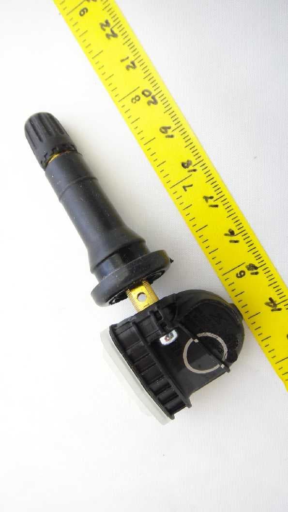
Click to zoom
Application Details
- Equipment Class
- DSC - Part 15 Security/Remote Control Transmitter
- Date of Grant
- Jan 12, 2014
- Application Purpose
- Original Equipment
- Date of Application
- Jan 12, 2014
- Equipment Note
- Tire Pressure Monitor
- Frequency Range
- 315.00000000 - 315.00000000
- Company
- Schrader Electronics
- Country
- Ireland
Documents & Files
Document Text
Text extracted from the exhibit documents filed with the FCC. Open a document above to read the original.
Users Manual
The device under test is manufactured by the grantee (Schrader Electronics) and sold as an OEM product. Per 47 CFR 2.909, 2.927, 2.931, 2.1033, 15.15(b) etc..., the grantee must ensure the end-user has all applicable / appropriate operating instructions. When end-user instructions are required, as in the case of this product, the grantee must notify the OEM to notify the end- user. Schrader Electronics will supply this document to the reseller/distributor dictating what must be included in the end user’s manual for the commercial product. INFORMATION TO BE INCLUDED IN THE END USER'S MANUAL The following information (in blue) must be included in the end product user’s manual to ensure continued FCC and Industry Canada regulatory compliance. The ID numbers must be included in the manual if the device label is not readily accessible to the end user. The compliance paragraphs below must be included in the user's manual. ****************************************************************************** FCC ID:MRXAG2SZ3IC:2546A- AG2SZ3 This device complies with Part 15 of the FCC Rules and with Licence exempt RSS standards of Industry Canada. Operation is subject to the following two conditions: (1)This device may not cause harmful interference, and (2)This device must accept any interference received, including interference that may cause undesired operation. Le présent appareil est conforme aux CNR d'Industrie Canada applicables aux appareils radio exempts de licence. L'exploitation est autorisée aux deux conditions suivantes: (1) l'appareil ne doit pas produire de brouillage, et (2) l'utilisateur de l'appareil doit accepter tout brouillage radioélectrique subi, même si le brouillage est susceptible d'encompromettre le fonctionnement. WARNING: Changes or modifications not expressively approved by the party responsible for compliance could void the user's authority to operate the equipment. The term “IC:” before the radio certification number only signifies that Industry Canada technical specifications were met. ******************************************************************************
Cover Letter(s)
Attn: Director of Certification Authority to Act as Agent I appoint Joseph D. Brunett on behalf of Willow Run Test Labs, LLC to act as our agent in the preparation of this application for equipment certification. I certify that submitted documents properly describe the device or system for which equipment certification is sought. I also certify that each unit manufactured, imported or marketed, as defined in Industry Canada’s regulations will have affixed to it a label identical to that submitted for approval with this application. For instances where our authorized agent signs the application for certification on our behalf, I acknowledge that all responsibility for complying with the terms and conditions for Certification, as specified by American Certification Body, Inc., still resides with ___( JAMES KYLE.UNIT II TECHNOLOGY PARK ANTRIM N.IRELAND BT411NU)___. Agency Agreement Expiration Date: February 27, 2015 Dated this 27 th day of February, 2013. By: JAMES KYLE_______________ (Signature) (Print name) Title: RF APPROVALS COORDINATOR email: [email protected] On behalf of: SCHRADER ELECTRONICS LD (Company Name) Telephone: 02894483067 Fax: N/A Federal Communications Commission Applications Processing Branch 7435 Oakland Mills Road Colombia, MD 21046 American Certification Body, Inc. 6731 Whittier Avenue Suite C110 McLean, VA 22101 To Whom It May Concern: Joseph D. Brunett on behalf of Willow Run Test Labs, LLC is authorized to act on our behalf, until otherwise notified, for applications to American Certification Body, Inc. (ACB). We certify that we are not subject to denial of federal benefits, that includes FCC benefits, pursuant to Section 5301 of the Anti-Drug Abuse Act of 1988, 21 U.S.C. 862. Further, no party, as defined in 47 CFR 1.2002 (b), to the application is subject to denial of federal benefits, that includes FCC benefits. Expiration Date: February 27, 2015 Dated this 27 th day of February, 2013. By: JAMES KYLE_______________ (Signature) (Print name) Title: RF APPROVALS COORDINATOR email: [email protected] On behalf of: SCHRADER ELECTRONICS LD (Company Name) Telephone: 02894483067 Fax: N/A
Cover Letter(s)
Willow Run Test Labs, LLC 8501 Beck Road, Building 2227 Belleville, MI 48111 Phone: (734) 252-9785, Fax (734) 926-9785 e-mail:[email protected] REQUEST FOR CONFIDENTIALITY Pursuant to FCC 47 CRF 0.457(d) and 0.459 and IC RSP-100, Section 10, Schrader requests that a part of the subject application be held confidential. Schrader has spent substantial effort in developing this product and it is one of the first of its kind in industry. Having the subject information easily available to "competition" would negate the advantage they have achieved by developing this product. Not protecting the details of the design will result in financial hardship. Type of Confidentiality RequestedExhibit Permanent Confidentiality:Schrader requests the exhibits listed above as permanently confidential be permanently withheld from public review. Short-Term Confidentiality (FCC Only):Schrader requests the exhibits selected above as short term confidential be withheld from public view for a period of 45 days from the date of the Grant of Equipment Authorization and prior to marketing. If there are any questions regarding this request, please contact me at the above address or call 734- 252-9785, fax 734-926-9785 or e-mail [email protected] Sincerely, Joseph D. Brunett, Ph.D. Willow Run Test Labs, LLC Check Box Check Box Check Box Check Box Check Box Check Box Check Box Check Box Check Box Check Box Check Box Check Box Check Box Check Box Check Box Check Box Short Term Permanent(1)ID Label & Location Short Term Permanent(3)External Photos Short Term Permanent 1 (4)Block Diagram Short Term Permanent(5)Schematics Short Term Permanent(7)Test Setup Photos Short Term Permanent(8)User’s Manual Short Term Permanent(9)Internal Photos Short Term Permanent(10)Parts List & Placement Short Term Permanent(11)RF Exposure Short Term Permanent(12)Description of Operation 1.Block Diagram includes internal oscillator frequency information that the manufacturer considers to be proprietary. Re:Certification for Schrader Electronics TPMS FCC ID: MRXAG2SZ3 IC: 2546A-AG2SZ3
Operational Description
Consumer Use Modes Manufacturing & Service Modes Mode of OperationExplanationFrequency of Transmission X Forced Transmission eg Tool LF / Factory LF (dealer / plant) On receipt of a particular LF sequence this Forced transmission allows the interrogation of the sensor in the vehicle factory or dealership Forced Transmission as required 9ASK + 4FSK (duration <1sec) X Off ModePart is in an off state, No transmissions, No exit by motionNo transmissions X Factory Mode (plant & test)Faster response mode used during testing at plant LF activation window 1secs. Timed transmissions every 15secs if in motion. X Stationary Mode Transmitter enters mode after First 24/36 Block (PAL/BMT) Drive Mode or 1min Drive Mode - Wheel is not rotating - Vehicle is stopped. Park mode (stationary transmission) every 6hours. 9ASK + 4FSK in Stationary modes X First 36 Block BMT (Drive Mode Non PAL enabled sensor) Enters mode upon exiting Stationary mode for first 36 transmissions. This mode is a function to learn the sensor IDs to confirm wheel positions on vehicle. Transmission rate every 15secs. 4 FSK frames in Rolling Modes X First 24 Block PAL (Drive Mode PAL enabled sensor) Enters mode upon exiting Stationary mode for first 24 transmissions. This mode is a function to learn the sensor IDs to confirm wheel positions on vehicle. Transmission rate typically 21.5secs (min 15secs). 4 FSK in Rolling Modes X Drive ModeTransmitter in normal operation - wheel is rotating Transmission rate every 60secs. 4 FSK in Rolling Modes X Drive ModeTransmitter in normal operation - wheel is rotating Transmission rate every 60secs. 4 FSK in Rolling Modes Pressure Measure ModePursuant to Section 15.231(a)(4), alarm conditions applyAlarm transmission as required
Test Report
Date of Issue: December 27, 2013Prepared For: Schrader ElectronicsTest Report No.: 20131227-01 Willow Run Test Labs, LLC 8501 Beck Road, Building 2227 Belleville, Michigan 48111 USA Tel: (734) 252-9785 Fax: (734) 926-9785 e-mail: [email protected] Testing of Electromagnetic Emissions per USA: CFR Title 47, Part 15.231(e) Canada: IC RSS-210/GENe are herein reported for Schrader Electronics AG2SZ3 Test Report No.: 20131227-01 Copyright c ©2013 Applicant/Provider: Schrader Electronics 11 Technology Park, Belfast Road, Antrim Northern Ireland BT41 1QS United Kingdom Phone: +44 28 9448 3067, Fax: +44 28 9446 8440 Contact Person: James Kyle; [email protected] Measured by: Report Approved by: Dr. Joseph Brunett, EMC-002790-NEDr. Joseph Brunett, EMC-002790-NE Report by: Report Date of Issue:December 27, 2013 Dr. Joseph Brunett, EMC-002790-NE Results of testing completed on (or before) December 27, 2013 are as follows. Emissions:The transmitter fundamental emission meets the regulatory limit(s) by no less than 14.6 dB. Trans- mit chain spurious harmonic emissions comply by no less than 26.4 dB. Willow Run Test Labs, LLC, 8501 Beck Road, Building 2227, Belleville, Michigan 48111 USAPage 1 of 14 Date of Issue: December 27, 2013Prepared For: Schrader ElectronicsTest Report No.: 20131227-01 Contents 1 Test Specifications, General Procedures, and Location3 1.1 Test Specification and General Procedures . . . . . . . . . . . . . . . . . . . . . . . . . . . . . . . . . .3 1.2 Test Location and Equipment Used . . . . . . . . . . . . . . . . . . . . . . . . . . . . . . . . . . . . . .4 2 Configuration and Identification of the Equipment Under Test5 2.1 Description and Declarations . . . . . . . . . . . . . . . . . . . . . . . . . . . . . . . . . . . . . . . . .5 2.1.1EUT Configuration . . . . . . . . . . . . . . . . . . . . . . . . . . . . . . . . . . . . . . . . . . .5 2.1.2Modes of Operation . . . . . . . . . . . . . . . . . . . . . . . . . . . . . . . . . . . . . . . . . .6 2.1.3Variants . . . . . . . . . . . . . . . . . . . . . . . . . . . . . . . . . . . . . . . . . . . . . . . . .6 2.1.4Test Samples . . . . . . . . . . . . . . . . . . . . . . . . . . . . . . . . . . . . . . . . . . . . . .6 2.1.5Functional Exerciser . . . . . . . . . . . . . . . . . . . . . . . . . . . . . . . . . . . . . . . . . .6 2.1.6Modifications Made . . . . . . . . . . . . . . . . . . . . . . . . . . . . . . . . . . . . . . . . . .6 2.1.7Production Intent . . . . . . . . . . . . . . . . . . . . . . . . . . . . . . . . . . . . . . . . . . .6 2.1.8Declared Exemptions and Additional Product Notes . . . . . . . . . . . . . . . . . . . . . . . .6 3 Emissions7 3.1 General Test Procedures . . . . . . . . . . . . . . . . . . . . . . . . . . . . . . . . . . . . . . . . . . . .7 3.1.1Radiated Test Setup and Procedures . . . . . . . . . . . . . . . . . . . . . . . . . . . . . . . . .7 3.1.2Conducted Emissions Test Setup and Procedures . . . . . . . . . . . . . . . . . . . . . . . . . .9 3.1.3Power Supply Variation . . . . . . . . . . . . . . . . . . . . . . . . . . . . . . . . . . . . . . . .9 3.1.4Thermal Variation . . . . . . . . . . . . . . . . . . . . . . . . . . . . . . . . . . . . . . . . . . .9 3.2 Intentional Emissions . . . . . . . . . . . . . . . . . . . . . . . . . . . . . . . . . . . . . . . . . . . . . . 10 3.2.1Fundamental Emission Pulsed Operation . . . . . . . . . . . . . . . . . . . . . . . . . . . . . . 10 3.2.2Fundamental Emission Bandwidth . . . . . . . . . . . . . . . . . . . . . . . . . . . . . . . . . . 12 3.2.3Fundamental Emission . . . . . . . . . . . . . . . . . . . . . . . . . . . . . . . . . . . . . . . . . 13 3.3 Unintentional Emissions . . . . . . . . . . . . . . . . . . . . . . . . . . . . . . . . . . . . . . . . . . . . 14 3.3.1Transmit Chain Spurious Emissions . . . . . . . . . . . . . . . . . . . . . . . . . . . . . . . . . 14 List of Tables 1Willow Run Test Labs, LLC Equipment List. . . . . . . . . . . . . . . . . . . . . . . . . . . . . . . . .4 2EUT Declarations. . . . . . . . . . . . . . . . . . . . . . . . . . . . . . . . . . . . . . . . . . . . . . . .5 3Pulsed Emission Characteristics (Duty Cycle). . . . . . . . . . . . . . . . . . . . . . . . . . . . . . . . 10 4Intentional Emission Bandwidth.. . . . . . . . . . . . . . . . . . . . . . . . . . . . . . . . . . . . . . 12 5Fundamental Radiated Emissions. . . . . . . . . . . . . . . . . . . . . . . . . . . . . . . . . . . . . . . 13 6Transmit Chain Spurious Emissions. . . . . . . . . . . . . . . . . . . . . . . . . . . . . . . . . . . . . . 14 List of Figures 1Photos of EUT.. . . . . . . . . . . . . . . . . . . . . . . . . . . . . . . . . . . . . . . . . . . . . . . .5 2EUT Test Configuration Diagram. . . . . . . . . . . . . . . . . . . . . . . . . . . . . . . . . . . . . . .6 3Radiated Emissions Diagram of the EUT. . . . . . . . . . . . . . . . . . . . . . . . . . . . . . . . . . .7 4Radiated Emissions Test Setup Photograph(s). . . . . . . . . . . . . . . . . . . . . . . . . . . . . . . .8 5Pulsed Emission Characteristics (Duty Cycle). . . . . . . . . . . . . . . . . . . . . . . . . . . . . . . . 11 5Pulsed Emission Characteristics (Duty Cycle). . . . . . . . . . . . . . . . . . . . . . . . . . . . . . . . 11 6Intentional Emission Bandwidth.. . . . . . . . . . . . . . . . . . . . . . . . . . . . . . . . . . . . . . 12 Willow Run Test Labs, LLC, 8501 Beck Road, Building 2227, Belleville, Michigan 48111 USAPage 2 of 14 Date of Issue: December 27, 2013Prepared For: Schrader ElectronicsTest Report No.: 20131227-01 1 Test Specifications, General Procedures, and Location 1.1 Test Specification and General Procedures The ultimate goal of Schrader Electronics is to demonstrate that the Equipment Under Test (EUT) complies with the Rules and/or Directives below. Detailed in this report are the results of testing the Schrader Electronics AG2SZ3 for compliance to: Country/RegionRules or DirectiveReferenced Section(s) United StatesCode of Federal RegulationsC…
Text truncated - open the document above for the full version.
Contact Information
Applicant
James Kyle
Technical Contact
Willow Run Test Labs, LLCJoseph Brunett
[email protected]7342529785
8501 Beck Road, Building 2227 · Belleville, Michigan · United States
Test Firm
Willow Run Test Labs, LLCJoseph Brunett
Technical Specifications
| # | Rule Parts | Frequency Range | Power Output |
|---|---|---|---|
| 1 | 15.231,15.231(e) | 315 MHz - 315 MHz | - |
Other Applications from Schrader Electronics
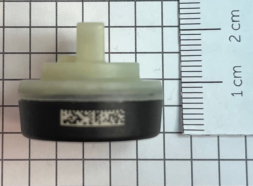
MRXFTMS01
Apr 17, 2024Tyre Pressure Monitor
Equipment Class
DSC - Part 15 Security/Remote Control Transmitter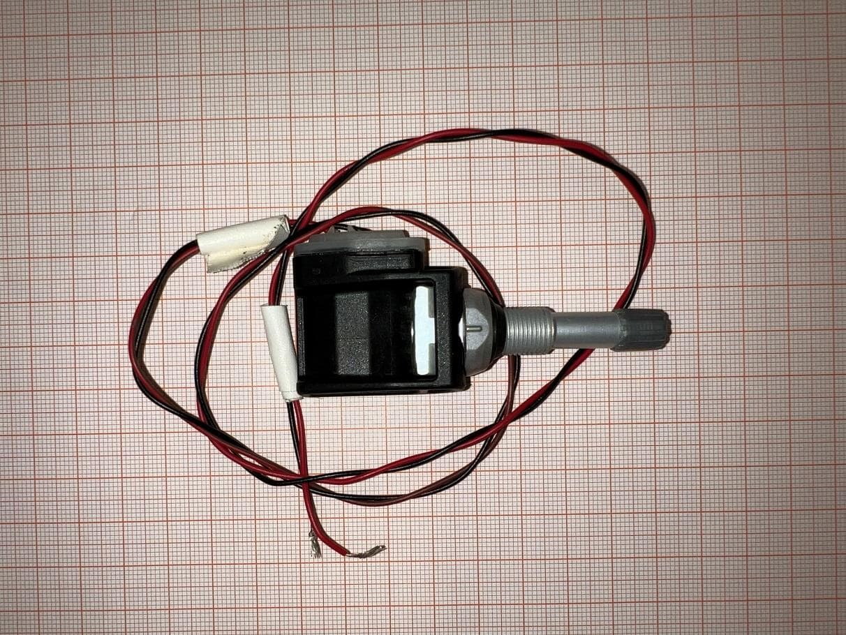
MRXBG6FD4
Jun 27, 2023Tyre Pressure Monitoring Sensor
Equipment Class
DSC - Part 15 Security/Remote Control Transmitter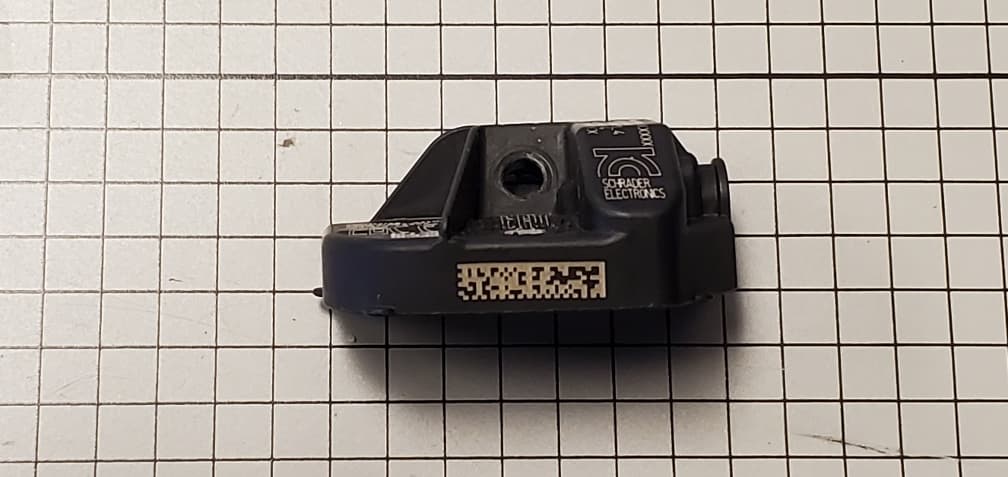
MRXBBFPL4
Mar 26, 2023TPMS Sensor
Equipment Class
DSC - Part 15 Security/Remote Control Transmitter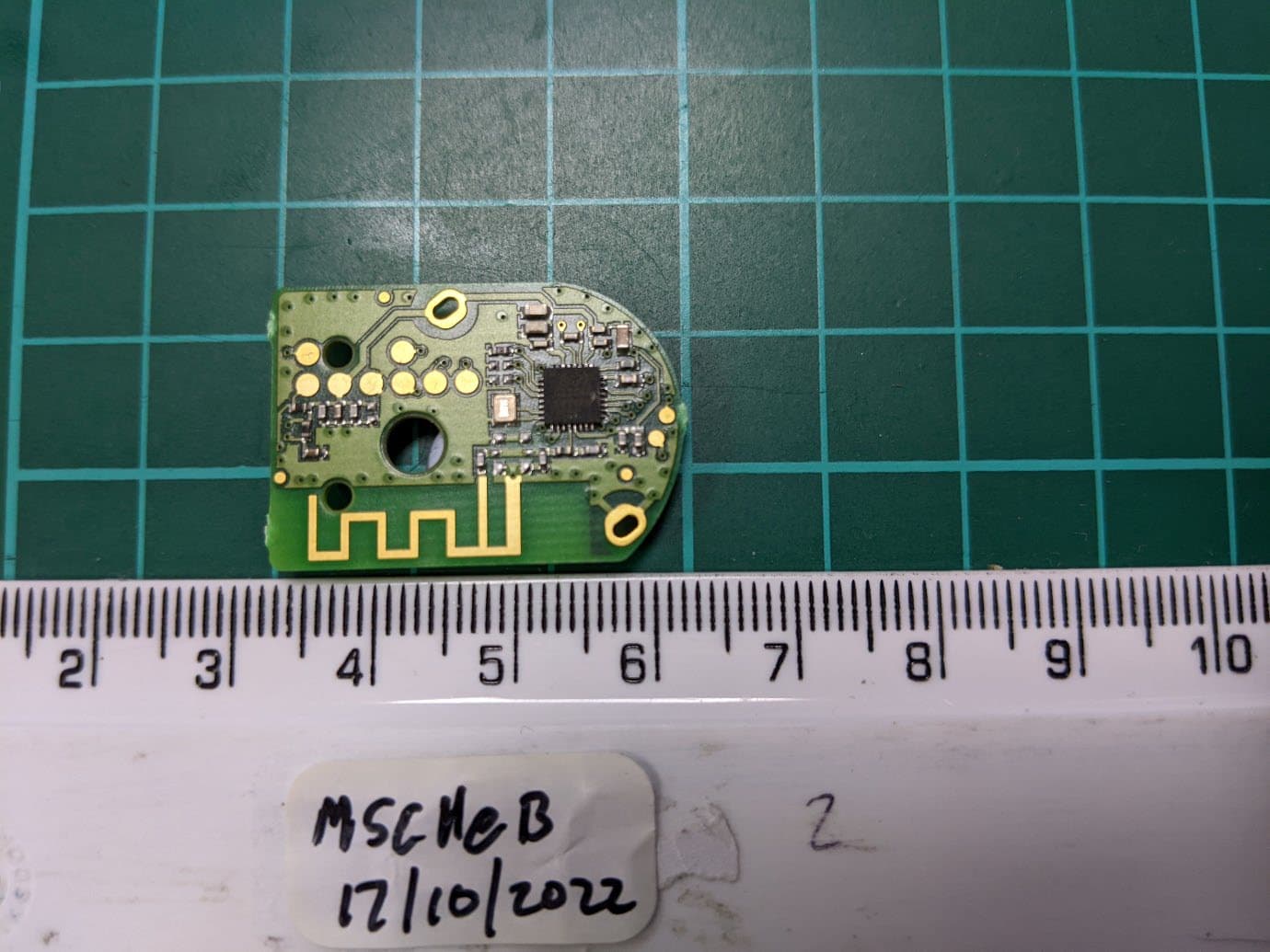
MRXSCHEB
Jan 25, 2023Tyre Pressure Monitoring System
Equipment Class
DTS - Digital Transmission System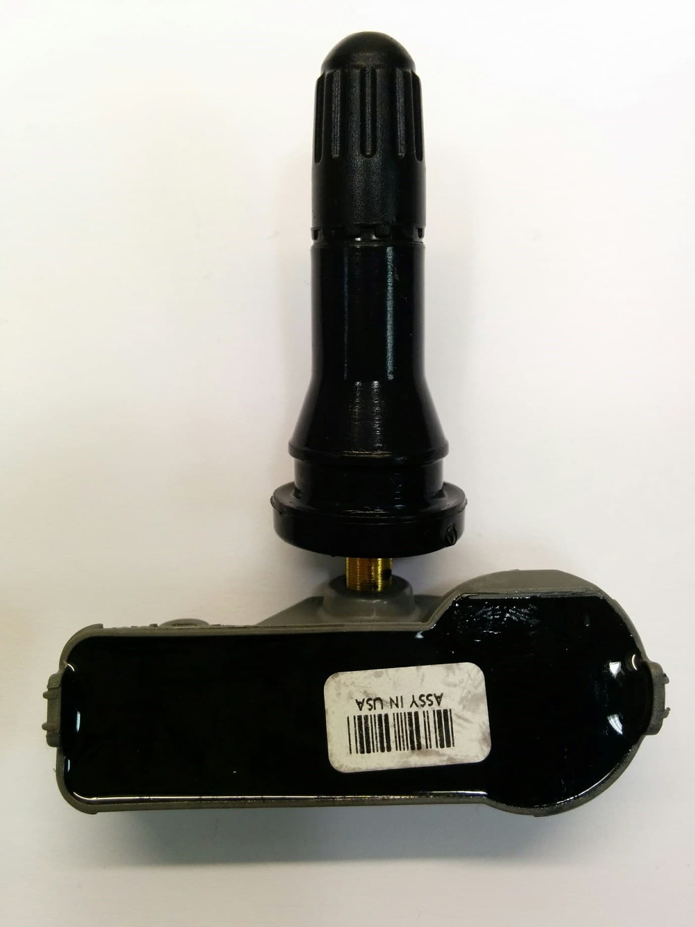
MRXFP4
Aug 30, 2022Tyre Pressure Monitor
Equipment Class
DSC - Part 15 Security/Remote Control Transmitter