MRXGME433TX1Remote Tire Pressure Sensor
Schrader Electronics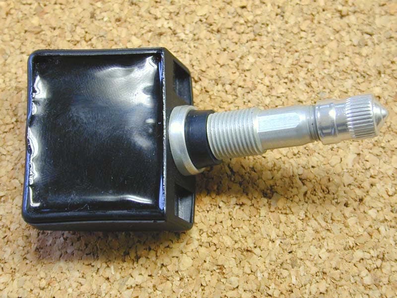
Click to zoom
Application Details
- Equipment Class
- DSC - Part 15 Security/Remote Control Transmitter
- Date of Grant
- Jan 08, 2003
- Application Purpose
- Original Equipment
- Date of Application
- Jan 08, 2003
- Equipment Note
- Remote Tire Pressure Sensor
- Frequency Range
- 433.92000000 - 433.92000000
- Company
- Schrader Electronics
- Country
- Ireland
Documents & Files
Document Text
Text extracted from the exhibit documents filed with the FCC. Open a document above to read the original.
Users Manual
Re: Certification for Schrader MRXGME433TX1 Transmitter Model: MRXGME433TX1 FCC ID: MRXGME433TX1 IC: 2546A-GMETX1 USER'S MANUAL INFORMATION (PRELIMINARY) The User's Manual is in preparation. The following material will be contained in the manual: FCC ID: MRXGME433TX1 IC: 2546A-GMETX1 This device complies with Part 15 of the FCC Rules and with RSS-210 of Industry Canada. Operation is subject to the following two conditions: (1) This device may not cause harmful interference, and (2) This device must accept any interference received, including interference that may cause undesired operation. WARNING: Changes or modifications not expressively approved by the party responsible for compliance could void the user's authority to operate the equipment. The term “IC:” before the radio certification number only signifies that Industry Canada technical specifications were met.
Cover Letter(s)
11 Technology Park, Belfast Road, Antrim. N.Ireland. BT41 1QS Letter of Agency February 26 th , 2001. American Telecommunications Certification Body Inc. 6731 Whittier Avenue Suite C110 McLean, VA 22101 Re : Power of Attorney for Valdis V. Liepa To Whom it may Concern : Please be advised that Schrader Electronics Ltd. authorises Valdis V. Liepa to act on our behalf, until otherwise notified, for applications submitted to American Telecommunications Certification Body, Inc ( ATCB ). We certify that we are not subject to denial of Federal benefits, that includes FCC benefits, pursuant to Section 5301 of the Anti-Drug Abuse ACT of 1988, U.S.C. 862. Further, no party, as defined in 47 CFR 1.2002(b), to the application is subject to denial of federal benefits, that includes FCC benefits. Thank you for your attention to this matter. Sincerely, Brendan McDonnell, Project Leader Schrader Electronics Ltd. Tel. +44 2894 482078 Fax +44 2894 468440 Date. Re: Certification for Schrader MRXGME433TX1 Transmitter Model: MRXGME433TX1 FCC ID: MRXGME433TX1 IC: 2546A-GMETX1 POWER OF ATTORNEY A letter granting Valdis V. Liepa the Power of Attorney is on file and can be provided when so requested. Re: Certification for Schrader MRXGME433TX1 Transmitter Model: MRXGME433TX1 FCC ID: MRXGME433TX1 IC: 2546A-GMETX1 REQUEST FOR CONFIDENTIALITY Pursuant to 47 CRF 0.459, Schrader requests that a part of the subject application be held confidential. This comprises Exhibits (5) Schematics (10) Parts List (Part of Exhibit only) Schrader has spent substantial effort in developing this product and it is one of the first of its kind in industry. Having the subject information easily available to "competition" would negate the advantage they have achieved by developing this product. Not protecting the details of the design will result in financial hardship. If there are any questions regarding this request, please contact me at the above address or call 734-483-4211, fax 734-647-2106 or e-mail [email protected]. Sincerely, Valdis V. Liepa Research Scientist University of Michigan December 9, 2002 Re: Certification for Schrader MRXGME433TX1 Transmitter Model: MRXGME433TX1 FCC ID: MRXGME433TX1 IC: 2546A-GMETX1 STATEMENT OF MODIFICATIONS There were no modifications made to the DUT by this test laboratory. (Also see Section 3.1 of the attached Test Report). _____________________ Valdis V. Liepa Research Scientist Re: Certification for Schrader MRXGME433TX1 Transmitter Model: MRXGME433TX1 FCC ID: MRXGME433TX1 IC: 2546A-GMETX1 GENERAL PRODUCT INFORMATION The device, for which certification is pursued, has been designed by: Schrader Electronics Limited 2546A-GMETX1 11 Technology Park, Belfast Road Antrim BT41 1QS, Northern Ireland Jim Newport Tel: 011-44-2894-48-2066 Fax: 011-44-1849-46-8440 It will be manufactured by: Schrader Electronics Limited 11 Technology Park, Belfast Road Antrim BT41 1QS, Northern Ireland Jim Newport Tel: 011-44-2894-48-2066 Fax: 011-44-1849-46-8440 Canadian Contact: Gates Rubber Co. 3303 Saint Etienne Boulevard Windsor, Ontario N8W 5B1 Contact: Karen McNamara +1 313 962-1711 ext. 250
Cover Letter(s)
American Telecommunications Certification Body Inc. 6731 Whittier Ave, McLean, VA 22101 December 15, 2002 RE: Schrader Electronics Limited FCC ID: MRXGME433TX1 After a review of the submitted information, I have a few comments on the above referenced Application. 1) The block diagram should show the frequencies of all oscillators in the device (CFR 2.1033(a)(5)). Please provide an updated version that includes this information. 2) Section 3 of the test report references a different FCC ID. Please explain and confirm if this is the correct report for this product. 3) The device was tested to show compliance with 15.231(e). The timing of the device appears to transmit the 8 ASK words in < 1 seconds, with a 60 second break between transmissions. This meets the timing requirements of 15.231(e). However the operational description (Learn Mode) mentions a 4 s transmission followed by a 5 second transmission. It is not certain how this device maintains the 15.231(e) timing requirements for this mode. Additionally, this references a LF and UHF transmission. Is this TX capable of transmitting on 2 different frequencies? 4) Please provide more information (i.e. such as the Appendix D referenced in the operational description), which shows the various TX timing elements for various modes of operation. For instance the Re-measure mode seems like it could violate the timing elements of 15.231(e). Timothy R. Johnson Examining Engineer mailto: [email protected] The items indicated above must be submitted before processing can continue on the above referenced application. Failure to provide the requested information may result in application termination. Correspondence should be considered part of the permanent submission and may be viewed from the Internet after a Grant of Equipment Authorization is issued. Please do not respond to this correspondence using the email reply button. In order for your response to be processed expeditiously, you must submit your documents through the AmericanTCB.com website. Also, please note that partial responses increase processing time and should not be submitted. Any questions about the content of this correspondence should be directed to the sender.
Cover Letter(s)
RE: Schrader Electronics Limited FCC ID: MRXGME433TX1 This is in response to the comments made on the above application. 1) The block diagram should show the frequencies of all oscillators in the device (CFR 2.1033(a)(5)). Please provide an updated version that includes this information. A revised block diagram has been uploaded. 2) Section 3 of the test report references a different FCC ID. Please explain and confirm if this is the correct report for this product. A revised test report has been uploaded. 3) The device was tested to show compliance with 15.231(e). The timing of the device appears to transmit the 8 ASK words in < 1 seconds, with a 60 second break between transmissions. This meets the timing requirements of 15.231(e). However the operational description (Learn Mode) mentions a 4 s transmission followed by a 5 second transmission. It is not certain how this device maintains the 15.231(e) timing requirements for this mode. Additionally, this references a LF and UHF transmission. Is this TX capable of transmitting on 2 different frequencies? 4) Please provide more information (i.e. such as the Appendix D referenced in the operational description), which shows the various TX timing elements for various modes of operation. For instance the Re-measure mode seems like it could violate the timing elements of 15.231(e). We have prepared a operational chart which shows the modes of operation for this transmitter, and applicable FCC rules. This should cover questions 3) and 4). One of the modes for activating the TPS (tire pressure sensor) is to use an LF (125 kHz) source/reader. This device puts the TPS into the Learn and Factory modes and also can read the ID of the TPS. The TPS acts as a passive transponder, using energy only from the incident LF field to modulate its receive coil.
Operational Description
1. Introduction 1.1 Purpose The purpose of this specification, is to relay the main characteristics of the Schrader-Bridgeport International Incorporated (SBII) RTPMS transmitter. This information is important for the design of either a stand-alone receiver or integration with the vehicle’s Remote Keyless Entry (RKE) receiver. 1.2 Scope This document applies to all customers who will be designing the RTPMS into part of their vehicular monitoring system. Schrader Bridgeport will supply the tyre pressure transmitters. The receiver may also be supplied by SBII to form a complete “stand alone” system, or the vehicle manufacturer may decide on integration with the vehicle’s RKE receiver. This document does not intend to restrict or specify any hardware or software. The intent is only to relay the transmission format of the tyre pressure monitoring data, the data protocol, the functionality and the key points of the RTPMS transmitter. 1.3 Overview The system has been developed to monitor a vehicle's tyre pressures whilst driving or stationary. An electronic unit inside each tyre, (referred to as the RTPMS transmitter) mounted to the valve stem, periodically measures actual tyre pressure. By means of RF communication, this pressure information is transmitted to a receiver/decoder. The receiver is used to decode the incoming radio frequency signals, format the data, and transfer the data to the proper display locations within the vehicle as required by the customer/supplier. 1.4 Definition ASIC- Application Specific Integrated Circuit. Generally, a custom designed integrated circuit (IC) manufactured for a unique application for a specific customer. Bit- Acronym for binary digit. A unit of information that can be represented by either logic zero (0) or a logic one (1). Bit width- The time set for one unit of information (bit). Block- In this document, a block is referred to as a group of eight transmitted words or frames. Check sum- Usually several bits of a word that signify the authenticity or correctness of the information (data) being sent. The check sum is usually compared against a calculated value in binary form. Customer- The person, or persons, who pay for the product and usually (but not necessarily) decide the requirements. Data Rate-The speed with which the data is transmitted or sent, usually in bits per second. Frame- One complete transmission of information. In this document, frame and word are used interchangeably and refer to the same thing. For this message, each frame contains one and only one message. A frame is delineated by the start of frame (SOF) mark. LF- Low Frequency 125 kHz. Low Battery Fault- A fault associated with a wheel transmitter, which indicates that a low battery function code has been sent. Low Pressure Threshold- Pressure level below which a low pressure alarm shall be generated by the receiver. Protocol- A set of conventions that govern the interaction of processes, devices, and other components within a system. Receiver- Device, supplied by the customer, that decodes the RTPMS data and then converts the data into information that can be used by the vehicular system. RF- Radio Frequency RTPMS- Remote Tire Pressure Monitoring System Supplier- The person, or persons, who produce a product for a customer. Start of Frame- The start of frame (SOF) mark is used to uniquely identify the start of a frame. Transmitter- The device that is mounted in the tyre that senses the tyre pressure and then sends the information via RF to the vehicle receiver. UHF- Ultra High Frequency ( 433.92 MHz ) Vehicle Trip- The period during which the roll switch is closed Word- A sequence of bits or characters that is stored, addressed, transmitted, and operated on as a unit within a given computer or processor. A sequence of bits or characters that has meaning and is considered an entity. Within this document, word and frame are used interchangeably. 2. Overall Description 2.1 Product Perspective 2.1.1 System Interface The RTPMS transmitter is one part of the RTPM System. The RTPMS requires an interface decoder (receiver). 2.1.2 Block Diagram See Appendix A “RTPMS Transmitter Block Diagram” 2.2 Product Functions 2.2.1 Major Functions The main functions, which the RTPMS transmitter has to perform, are: • Monitor and transmit tyre pressure. • Determination of a temperature compensated pressure value. • Inform the receiver of any low battery condition. • Determine if there are abnormal pressure variations in the wheel. 2.3 Constraints 2.3.1 ETSI 300/220 The 433.92 MHz version meets the requirements of the European Telecommunications Standard Institute 300/220 regulations. Individual country approvals need to be applied for. Division of cost to be negotiated. 2.3.2 FCC Regulations The 433.92 MHz version meets the requirements of the Federal Communications Commission regulations Part 15. The environmental conditions, including ESD (electrostatic discharge), EMC (electromagnetic compatibility), temperature, vibration etc. which the transmitter must be able to withstand are described in the “Schrader-Bridgeport RTPM Generic Validation Specification” document. 2.4 Assumptions and Dependencies 2.4.1 AM versus FM The standard Schrader Bridgeport RTPMS transmitter transmits using amplitude modulation (AM). An FM version can also be supplied. 2.4.2 Carrier Frequency In the USA, the transmission frequency is 433.92 MHz. 3. Specific Requirements 3.1 Functions 3.1.1 Operational Description The function of the receiver is to decode the information sent by the RTPMS transmitter and indicate the pressure to the end user. It is the responsibility of the customer to determine how the information is displayed to the end-user and what levels of warnings are given. SBII can however offer advice in this area. The display can be in the form of a display, bulbs, buzzer, or even voice synthesis to warn the driver of the abnormal pressures. Dependent on the state of the vehicle, the RTPMS transmitter will sense …
Text truncated - open the document above for the full version.
Operational Description
MRXGME433TX1 Consumer Use Modes Manufacturing & Service Modes Mode of OperationExplanationFrequency of Transmission X Roll Mode (Drive mode)Transmitter in normal operation - wheel is rotating and roll switch is closed8 words every 60 seconds X Learn Mode Transmits 40 words after magnetic or LF transponder activation or when sensor exits Off mode due to Roll switch closure 40 words for 1 transmission, < 5secs X Factory Mode. Transmitter is in Factory mode for the next 16 or fewer Roll Switch closures after a Learn activation. The Wheel has to be rotating (roll switch closed) 8 words every 10 seconds. XX Stationary Mode Transmitter enters mode after Factory Mode or Drive Mode - Wheel is not rotating - Vehicle is stopped. no transmission X Wake Mode Transmit 8 words when sensor transitions from Stationary mode to Drive mode due to Roll switch closure 8 words for 1 transmission XX Off ModeTransmit 8 words when sensor transitions to Off mode8 words for 1 transmission X Low Battery Mode X Re-measure Mode XX Sleep ModeAll of the time between the other modesno transmission Notes: 3) 8 word packet is < 1sec in duration Pursuant to Section 15.231(a)(4), alarm conditions apply for these two modes as they occur only during sudden change in tire pressure or at the time of low battery, per conversations with FCC. 1) The manufacturing and service modes fall under FCC Part 2.803(d),2.803(e)(1)(iv),(v), and 2.803(e)(2). These modes are used to setup and program the tire pressure monitoring system on the vehicle and will be used in factory and service environments (i.e. vehicle/tire dealers) only. Since these procedures require special equipment and training, they will not be evoked by the consumer. 2) Power levels of all transmissions are the same
Contact Information
Applicant
James Kyle
Technical Contact
University of Michigan/EECSValdis V Liepa
[email protected]734-483-4211
1301 Beal Ave. · Ann Arbor, Michigan · United States
Non-Technical Contact
University of Michigan/EECSValdis V Liepa
[email protected]734-483-4211
Test Firm
University of MichiganValdis Liepa
Technical Specifications
| # | Rule Parts | Frequency Range | Power Output |
|---|---|---|---|
| 1 | 15.231(e) | 433.92 MHz - 433.92 MHz | - |
Other Applications from Schrader Electronics
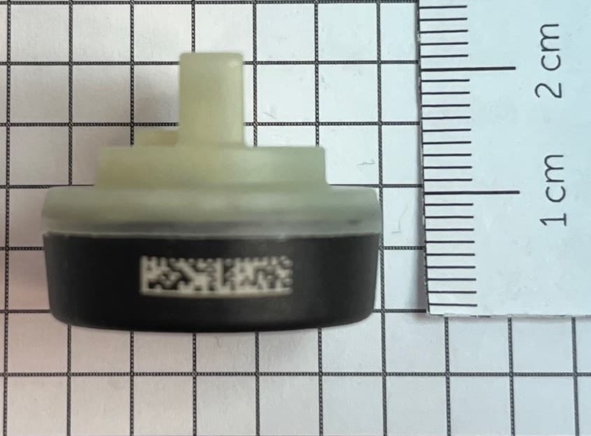
MRXFTMS01
Apr 17, 2024Tyre Pressure Monitor
Equipment Class
DSC - Part 15 Security/Remote Control Transmitter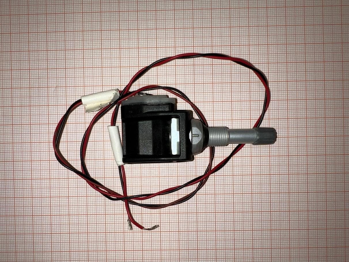
MRXBG6FD4
Jun 27, 2023Tyre Pressure Monitoring Sensor
Equipment Class
DSC - Part 15 Security/Remote Control Transmitter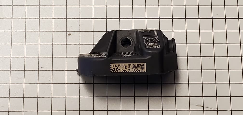
MRXBBFPL4
Mar 26, 2023TPMS Sensor
Equipment Class
DSC - Part 15 Security/Remote Control Transmitter
MRXSCHEB
Jan 25, 2023Tyre Pressure Monitoring System
Equipment Class
DTS - Digital Transmission System
MRXFP4
Aug 30, 2022Tyre Pressure Monitor
Equipment Class
DSC - Part 15 Security/Remote Control Transmitter