MRXMFRTyre Pressure Monitoring Sensor ECU
Schrader Electronics
Click to zoom
Application Details
- Equipment Class
- JBP - Part 15 Class B Computing Device Peripheral
- Date of Grant
- Nov 04, 2015
- Application Purpose
- Original Equipment
- Date of Application
- Nov 03, 2015
- Equipment Note
- Tyre Pressure Monitoring Sensor ECU
- Frequency Range
- 433.92000000 - 433.92000000
- Company
- Schrader Electronics
- Country
- Ireland
Documents & Files
Document Text
Text extracted from the exhibit documents filed with the FCC. Open a document above to read the original.
Users Manual
Schrader Electronics Ltd. 11 Technology Park, Belfast Road, Antrim BT41 1QS, Northern Ireland United Kingdom Schrader Electronics Ltd. Model: MFR TPMS ECU Receiver User Manual Introduction The TPMS ECU will serve as the interface between TPMS Transmitters and the CAN communications bus within the Vehicle. The TPMS ECU will receive RF transmissions from the Transmitters. It will decode and analyse these transmissions and provide data on the tyre pressure and temperature and location for each wheel on the vehicle. Based on the data from the Transmitters and an algorithm developed, the TPMS ECU will report warnings and tyre pressures over the CAN bus. The TPMS ECU will be installed in a position on the vehicle to be agreed between Schrader and the Customer. The TPMS ECU location is key to its correct operation. It is expected that the CAN interface will be fixed and that different displays can be supported without any update to the Schrader TPMS ECU. The receiver ECU shall decode the incoming RF signals, format the data, and transfer the data to the CAN bus within the vehicle as required by the customer or supplier. The system shall also automatically detect the wheel locations of each transmitter on the vehicle. Environmental compatibility requirements The TPMS ECU shall operate without degradation over the temperature range -40°C to +105°C. All components of the TPMS ECU shall be rated to a temperature range which covers -40o C to +105o C. The TPMS ECU Enclosure is resilient against the environment in which it is to be placed. The TPMS ECU complies with ETSI (RTTE governed), FCC (USA) and IC (Canada) regulatory requirements. Schrader Electronics Ltd. 11 Technology Park, Belfast Road, Antrim BT41 1QS, Northern Ireland United Kingdom Regulatory Compliance FEDERAL COMMUNICATIONS COMMISSION INTERFERENCE STATEMENT This equipment has been tested and found to comply with the limits for a Class B digital device, pursuant to part 15 of the FCC Rules. These limits are designed to provide reasonable protection against harmful interference in a residential installation. This equipment generates, uses and can radiate radio frequency energy and, if not installed and used in accordance with the instructions, may cause harmful interference to radio communications. However, there is no guarantee that interference will not occur in a particular installation. If this equipment does cause harmful interference to radio or television reception, which can be determined by turning the equipment off and on, the user is encouraged to try to correct the interference by one or more of the following measures: -Reorient or relocate the receiving antenna. -Increase the separation between the equipment and receiver. -Connect the equipment into an outlet on a circuit different from that to which the receiver is connected. -Consult the dealer or an experienced radio/ TV technician for help. (Section 15.21) CAUTION: Any changes or modifications not expressly approved by the grantee of this device could void the user's authority to operate the equipment. Label: ( Section 15.19)(a)(3) This device complies with Part 15 of the FCC Rules. Operation is subject to the following two conditions: (1) this device may not cause harmful interference, and (2) this device must accept any interference received, including interference that may cause undesired operation
External Photos
Report No.: 1550297R-RFUSP14V00 Page : 1 of 7 Attachment 2 : EUT Detailed Photographs (1) EUT Photo (2) EUT Photo Report No.: 1550297R-RFUSP14V00 Page : 2 of 7 (3) EUT Photo (4) EUT Photo Report No.: 1550297R-RFUSP14V00 Page : 3 of 7 (5) EUT Photo (6) EUT Photo
ID Label/Location Info
Model: MFR Receiver ECU for Tyre Pressure Monitoring Sensor
ID Label/Location Info
Model: MFR Receiver ECU for Tyre Pressure Monitoring Sensor Label
Internal Photos
Report No.: 1550297R-RFUSP14V00 Page : 4 of 7 (7) EUT Photo (8) EUT Photo Report No.: 1550297R-RFUSP14V00 Page : 5 of 7 (9) EUT Photo (10) EUT Photo Antenna Report No.: 1550297R-RFUSP14V00 Page : 6 of 7 (11) EUT Photo (12) EUT Photo Report No.: 1550297R-RFUSP14V00 Page : 7 of 7 (13) EUT Photo (14) EUT Photo
Test Report
Report No.:1550297R-RFUSP14V00 Page : 1 of 18 FCC Test Report Product Name Tyre Pressure Monitoring Sensor ECU Model No. MFR FCC ID MRXMFR Applicant Schrader Electronics Ltd. Address 11 Technology Park, Belfast Road, Antrim, BT41 1QS, Northern Ireland Date of Receipt May 12, 2015 Issued Date June 09, 2015 Report No. 1550297R-RFUSP14V00 Report Version V2.0 The test results relate only to the samples tested. The test results shown in the test report are traceable to the national/international standard through the calibration report of the equipment and evaluated measurement uncertainty herein. This report must not be used to claim product endorsement by TAF or any agency of the government. The test report shall not be reproduced without the written approval of QuieTek Corporation. Report No.:1550297R-RFUSP14V00 Page : 2 of 18 Test Report Issued Date: June 09, 2015 Report No.: 1550297R-RFUSP14V00 Product Name Tyre Pressure Monitoring Sensor ECU Applicant Schrader Electronics Ltd. Address 11 Technology Park, Belfast Road, Antrim, BT41 1QS, Northern Ireland Manufacturer Schrader Electronics Ltd. Model No. MFR EUT Rated Voltage DC 12V (Power by Battery ) EUT Test Voltage DC 12V (Power by Battery ) Trade Name SCHRADER ELECTRONICS Applicable Standard FCC CFR Title 47 Part 15 Subpart B: 2014 ANSI C63.4: 2009, ANSI C63.10: 2009 RSS-Gen Issue 4 (Nov, 2014) ANSI C63.4: 2014, ANSI C63.10: 2013 Test Result Complied Documented By : ( Senior Adm. Specialist / Rita Huang ) Tested By : ( Assistant Engineer / Ivan Chuang ) Approved By : ( Director / Vincent Lin ) Report No.:1550297R-RFUSP14V00 Page : 3 of 18 TABLE OF CONTENTS Description Page 1. GENERAL INFORMATION.................................................................................................4 1.1. EUT Description ........................................................................................................................4 1.2. Test System Details....................................................................................................................5 1.3. Configuration of Test System ....................................................................................................5 1.4. EUT Exercise Software..............................................................................................................5 1.5. Test Facility................................................................................................................................6 2. Conducted Emission................................................................................................................7 2.1. Test Equipment ..........................................................................................................................7 2.2. Test Setup...................................................................................................................................7 2.3. Limits .........................................................................................................................................7 2.4. Test Procedure............................................................................................................................8 2.5. Uncertainty.................................................................................................................................8 2.6. Test Result of Conducted Emission ...........................................................................................9 3. Radiated Emission.................................................................................................................10 3.1. Test Equipment ........................................................................................................................10 3.2. Test Setup.................................................................................................................................11 3.3. Limits .......................................................................................................................................12 3.4. Test Procedure..........................................................................................................................12 3.5. Uncertainty...............................................................................................................................13 3.6. Test Result of Radiated Emission ............................................................................................14 4. EMI Reduction Method During Compliance Testing ........................................................16 Attachment 1: EUT Test Photographs Attachment 2: EUT Detailed Photographs Report No.:1550297R-RFUSP14V00 Page : 4 of 18 1. GENERAL INFORMATION 1.1. EUT Description Product Name Tyre Pressure Monitoring Sensor ECU Trade Name SCHRADER ELECTRONICS Model No. MFR Frequency Range 433.92 MHz Type of Modulation FSK Number of Channels 1 Antenna Type Integral Antenna Channel Control Auto Frequency of Each Channel Channel Frequency Channel 1: 433.92 MHz Note: 1. The EUT is a Tyre Pressure Monitoring Sensor ECU with a built-in Z-wave Receiver module. 2. These tests are conducted on a sample of the equipment for the purpose of demonstrating compliance with Part 15 Subpart B. Test Mode Mode 1: Receive Mode Report No.:1550297R-RFUSP14V00 Page : 5 of 18 1.2. Test System Details The types for all equipment, plus descriptions of all cables used in the tested system (including inserted cards) are: 1 Monitor Dell ST2320L3 CN-0M2NN672872-22I-C9WWS Non-Shielded, 1.8m 2 Battery TRANE 12B50PE N/A N/A Signal Cable Type Signal cable Description A Power Cable Non-Shielded, 1.2m B Signal Cable Non-Shielded, 3.4m 1.3. Configuration of Test System 1.4. EUT Exercise Software (1) Setup the EUT as shown in section 1.3. (2) Porvide the DC Power Source. (3) Start receives mode continually. (4) Verify that the EUT works properly. Report No.:1550297R-RFUSP14V00 Page : 6 of 18 1.5. Test Facility Ambient conditions in the lab…
Text truncated - open the document above for the full version.
Test Setup Photos
Report No.: 1550297R-RFUSP14V00 Page : 1 of 2 Attachment 1: EUT Test Setup Photographs Front View of Radiated Test Back View of Radiated Test Report No.: 1550297R-RFUSP14V00 Page : 2 of 2 Front View of Radiated Test (Horn) Back View of Radiated Test (Horn)
Contact Information
Applicant
James Kyle
Technical Contact
QuieTek CorporationMaggie Chen
[email protected]886-2-8601-3788
No.5-22, Rueishu Keng, Linkou Dist., · Taiwan
Non-Technical Contact
QuieTek CorporationMaggie Chen
[email protected]886-2-8601-3788
Test Firm
DEKRA TESTING AND CERTIFICATION CO., LTD. LinKouMirenda Liao
Technical Specifications
| # | Rule Parts | Frequency Range | Power Output |
|---|---|---|---|
| 1 | 15B | 433.92 MHz - 433.92 MHz | - |
Other Applications from Schrader Electronics
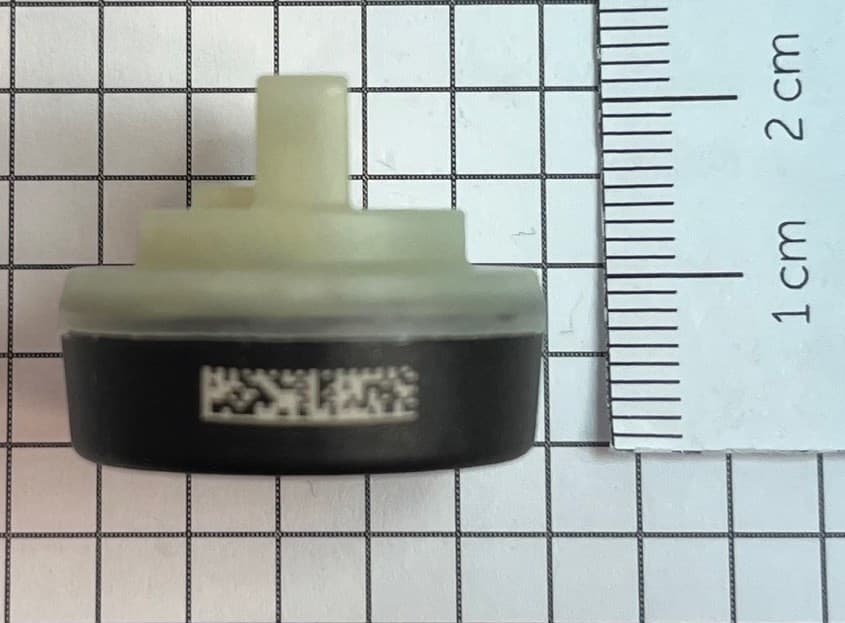
MRXFTMS01
Apr 17, 2024Tyre Pressure Monitor
Equipment Class
DSC - Part 15 Security/Remote Control Transmitter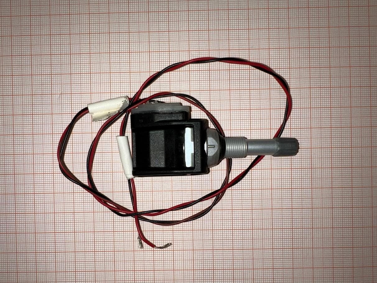
MRXBG6FD4
Jun 27, 2023Tyre Pressure Monitoring Sensor
Equipment Class
DSC - Part 15 Security/Remote Control Transmitter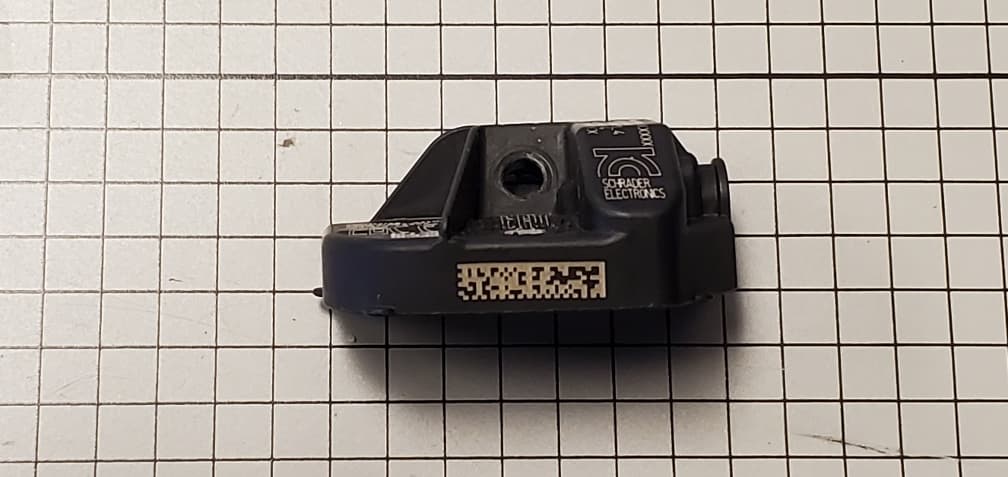
MRXBBFPL4
Mar 26, 2023TPMS Sensor
Equipment Class
DSC - Part 15 Security/Remote Control Transmitter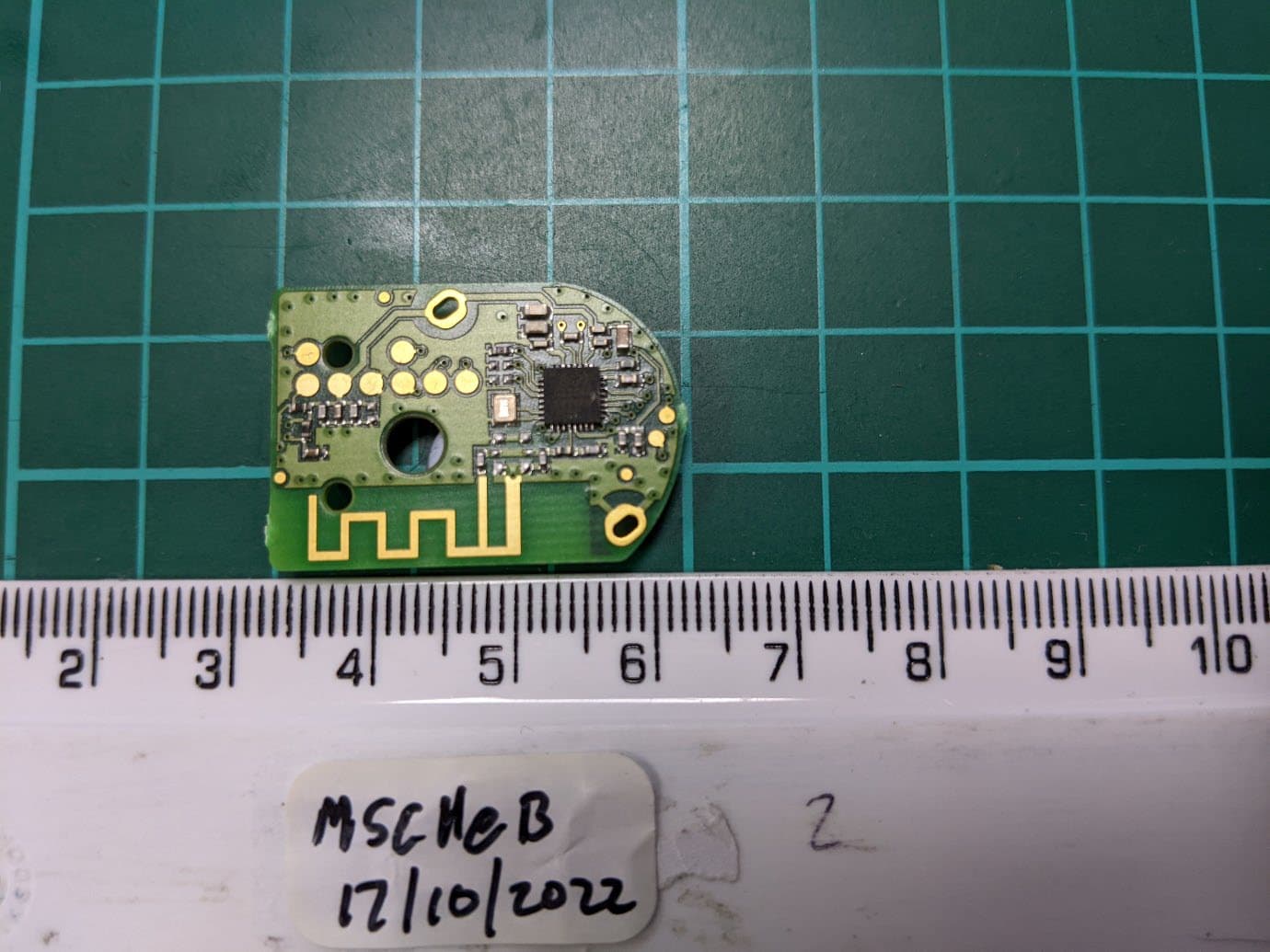
MRXSCHEB
Jan 25, 2023Tyre Pressure Monitoring System
Equipment Class
DTS - Digital Transmission System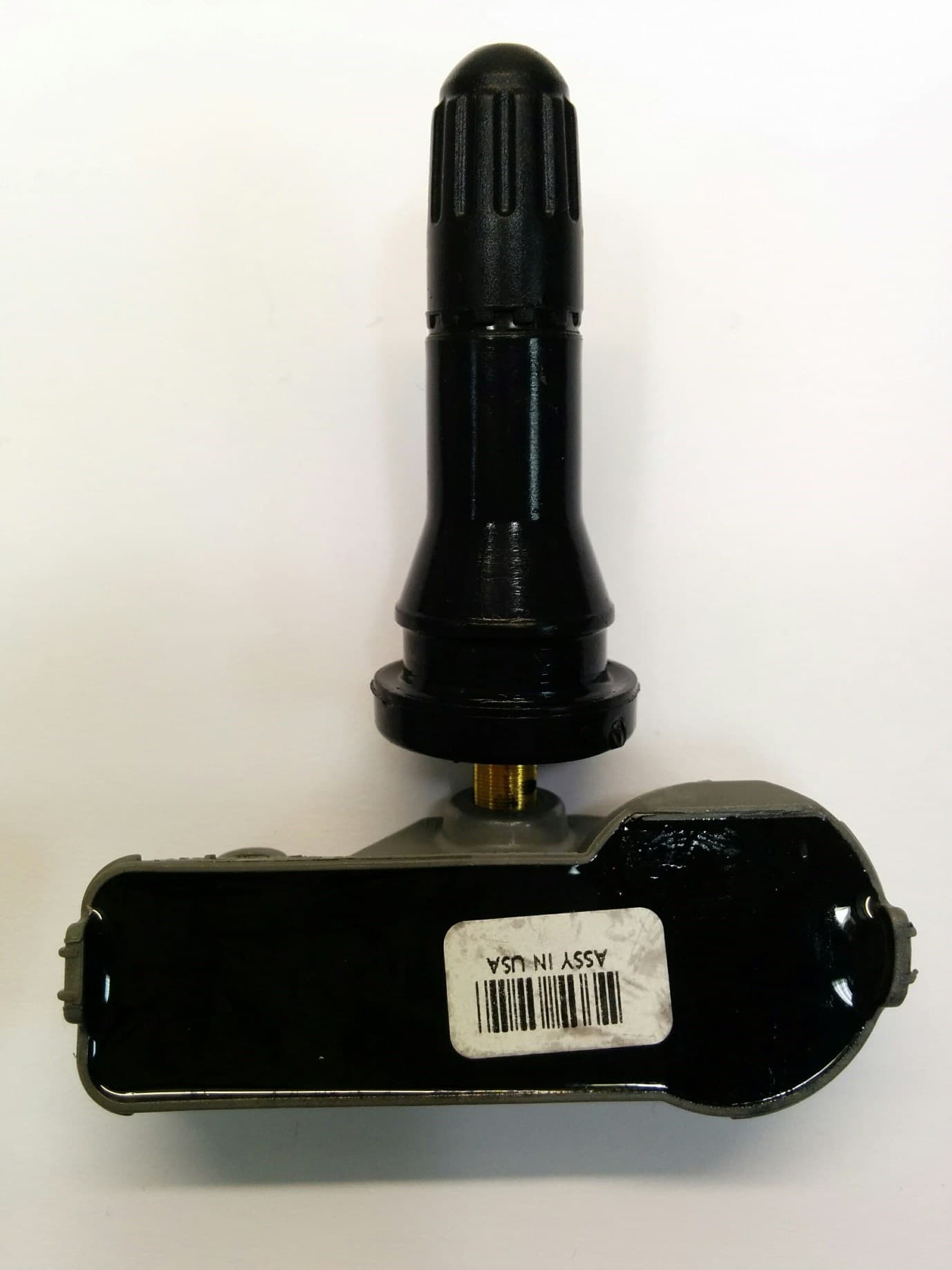
MRXFP4
Aug 30, 2022Tyre Pressure Monitor
Equipment Class
DSC - Part 15 Security/Remote Control Transmitter