MRXPTPMS13Tire Pressure Monitoring Transmitter
Schrader Electronics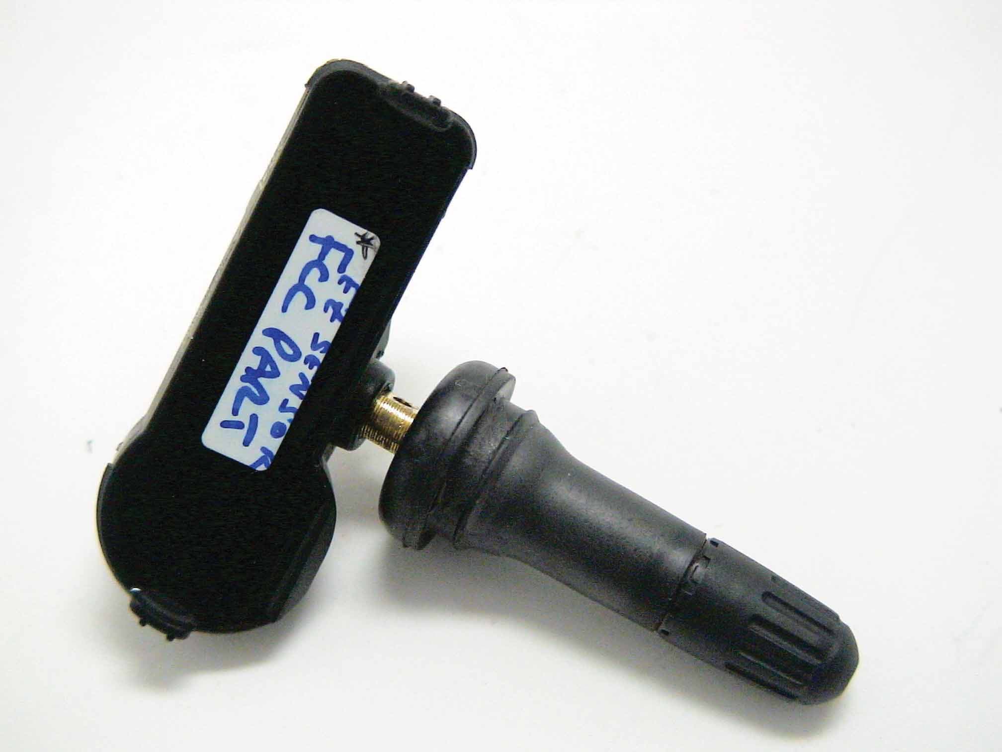
Click to zoom
Application Details
- Equipment Class
- DSC - Part 15 Security/Remote Control Transmitter
- Date of Grant
- Oct 24, 2010
- Application Purpose
- Original Equipment
- Date of Application
- Oct 21, 2010
- Equipment Note
- Tire Pressure Monitoring Transmitter
- Frequency Range
- 315.00000000 - 315.00000000
- Company
- Schrader Electronics
- Country
- Ireland
Documents & Files
Document Text
Text extracted from the exhibit documents filed with the FCC. Open a document above to read the original.
Users Manual
The EZ Sensor is manufactured by the grantee (Schrader Electronics) and sold as an OEM product to automobile dealerships and tire installers. Per 47 CFR 2.909, 2.927, 2.931, 2.1033, 15.15(b) etc..., the grantee must ensure the end-user has all applicable / appropriate operating instructions. When end-user instructions are required, as in the case of this product, the grantee must notify the OEM to notify the end user. Schrader Electronics will supply the following user’s manual to the reseller/distributor and require them to provide this information to the end user at the time of installation. EZ Sensor END CONSUMER USER MANUAL The Schrader Electronics EZ Sensor is a configurable sensor designed to be used in a direct measurement TPM (Tire Pressure Monitoring) System. The TPM Sensor is intended to interface to a receiver/decoder that has been designed to accept the TPM sensor protocol. The TPM Sensor is designed to monitor a vehicle's tyre pressure whilst driving or stationary. An electronic unit inside each tyre (referred to as the TPM Sensor or TPM transmitter) mounted to the valve stem, periodically measures actual tyre pressure/temperature. By means of an RF link, this pressure information is transmitted to a receiver/decoder. The incoming radio frequency signals are decoded, and the data used to inform the driver of the tyre pressure information via the vehicles TPM interface. TPM Sensor main functions are: • Regularly measure the tyre pressure. • Monitor if the wheel is moving. • Periodically transmit tyre pressure using an RF link and a specific protocol. • Monitor condition of the battery and notify the system during an RF transmission if the battery performance degrades. • Notify the system if there are abnormal pressure variations (leak) in the tyre. NOTICE: This device complies with Part 15 of the FCC Rules and with RSS-210 of Industry Canada. Operation is subject to the following two conditions: (1) This device may not cause harmful interference, and (2) This device must accept any interference received, including interference that may cause undesired operation. WARNING: Changes or modifications not expressively approved by the party responsible for compliance could void the user's authority to operate the equipment. The term “IC:” before the radio certification number only signifies that Industry Canada technical specifications were met.
Cover Letter(s)
October 21, 2010 Federal Communications Commission Equipment Approval Services P.O. Box 358315 Pittsburgh, PA 15251-5315 Re: Certification for Schrader Transmitter Model/PN(s): PTPMS13 FCC ID: MRXPTPMS13 IC: 2546A-PTPMS13 Please find enclosed application materials for certification of Schrader Transmitter. We tested it and found it to comply with FCC Part 15. If there are any questions regarding the application or testing performed, please contact me at the above address or call 734-483-4211, fax 734-647-2106, or e-mail [email protected]. Sincerely, Valdis V. Liepa Research Scientist
Cover Letter(s)
Federal Communications Commission Applications Processing Branch 7435 Oakland Mills Road Colombia, MD 21046 Re: Letter of Agency for FCC Compliance Testing Please be advised that Schrader Electronics authorizes Professor Valdis V. Liepa of the University of Michigan, Department of Electrical Engineering and Computer Science, Ann Arbor, Michigan, to act on our behalf in front of the Federal Communications Commission with respect to all matters relating to certification. Anti-Drug Abuse Certification: I further certify that no party (as defined in 1.2002 of CFR47, 1992) to this application, including myself, is subject to a denial of federal benefits, that includes FCC benefits, pursuant to Section 5301 of the Anti Drug Abuse Act of 1988, 21 U.S.C. 853(a). Dated this 15 day of March, 2007 By: ___________ _____________ __Adrian Condon (Signature) (Print name) Title: _EMC & Approvals Team Leader_ _____________ _ email: [email protected]_ On behalf of: ___ Schrader Electronics _______ (Company Name) Telephone: __ 0044 2894483073 ___
Cover Letter(s)
Re: Certification for Schrader Transmitter FCC ID: MRXPTPMS13 IC: 2546A-PTPMS13 REQUEST FOR CONFIDENTIALITY Pursuant to FCC 47 CRF 0.457(d) and 0.459 and IC RSP-100, Section 10, Schrader requests that a part of the subject application be held confidential. Schrader has spent substantial effort in developing this product and it is one of the first of its kind in industry. Having the subject information easily available to "competition" would negate the advantage they have achieved by developing this product. Not protecting the details of the design will result in financial hardship. Type of Confidentiality Requested Exhibit Short Term Permanent (1) ID Label & Location Short Term Permanent (3) External Photos Short Term Permanent 1 (4) Block Diagram Short Term Permanent (5) Schematics Short Term Permanent (7) Test Setup Photos Short Term Permanent (8) User’s Manual Short Term Permanent 2 (9) Internal Photos Short Term Permanent (10) Parts List & Placement Short Term Permanent (11) RF Exposure Short Term Permanent 3 (12) Description of Operation 1. Block Diagram includes internal oscillator frequency information that the manufacturer considers to be proprietary. 2. DUT is FULLY potted using a non-removable epoxy based material. Removal of potting material causes irreparable damage to internal circuitry. Photograph exhibits outline the half- clam-shell device before and after potting. 3. A portion of the Description of Operation exhibit contains information relating to the operation and programming of this device that the manufacturer considers to be proprietary. Permanent Confidentiality: Schrader requests the exhibits listed above as permanently confidential be permanently withheld from public review. Short-Term Confidentiality (FCC Only): Schrader requests the exhibits selected above as short term confidential be withheld from public view for a period of 45 days from the date of the Grant of Equipment Authorization and prior to marketing. If there are any questions regarding this request, please contact me at the above address or call 734-483-4211, fax 734-647-2106 or e-mail [email protected]. Sincerely, Valdis V. Liepa, Research Scientist University of Michigan
Cover Letter(s)
FCC Home | Search | Updates | E-Filing | Initiatives | For Consumers | Find People Joseph Brunett <[email protected]> Response to Inquiry to FCC (Tracking Number 280186) oetech@fccsun27w .fcc.gov <oetech@fccsun27w .fcc.gov>Mon, Nov 17, 2008 at 4:48 PM To: [email protected] Office of Engineering and Technology Inquiry: --- Reply from Customer on 11/08/2008 --- I have just been informed by my TCB that their PBA request for the same devices does not match with this response. They are asking that, per Inquiry 751504, I provide a detailed explanation of how the devices are potted, what the potting material is, how its removal destroys the pcb, and leave me with the impression that a PBA may be needed for every application. Please note that the chemical makeup of the potting material may in itself need to remain confidential as it is proprietary in this industry (not may materials can handle 30g's). Please correspond with the reviewer of KDB Inquiry 751504, relay that internal photographs provided without potting are not obtained by "removing" the potting material, but are "pre-potted" photos, and provide both inquiries with a single, consistent, request for more information if needed. Please indicate if additional PBA requests will be required for every like application. I apologize if the tone of this response seems harsh, I do not mean it to be. However, every delay caused by inconsistent responses requires that I call my clients, outline the problem, request additional information, and request their patience. The current climate in the auto industry makes the final request more challenging as of late. ;) JDB Response: You should not need a PBA request for every filing since you may reference this KDB in each subsequent filing for similar device. Do not reply to this message. Please select the Reply to an Inquiry Response link from the OET Inquiry System to add any additional information pertaining to this inquiry. 10/21/2010Gmail - Response to Inquiry to FCC (Tr... https://mail.google.com/mail/?ui=2&ik...1/1
Test Report
University of Michigan Radiation Laboratory FCC Part 15, IC RSS-210/Gen - Test Report No. 417124-586 Page 1 of 14 The University of Michigan Radiation Laboratory 3228 EECS Building Ann Arbor, MI 48109-2122 Tel: (734) 764-0500 Fax: (734) 647-2106 Measured Radio Frequency Emissions From Schrader Electronics Limited Transmitter FCC ID: MRXPTPMS13 IC: 2546A-PTPMS13 Test Report No. 417124-586 October 21, 2010 Copyright © 2010 For: Schrader Electronics Limited 11 Technology Park, Belfast Road, Antrim BT41 1QS, Northern Ireland Contact: Adrian Condon, [email protected] Phone: +44 (0) 28 9448 3073 Fax: +44 (0) 28 9446 8440 Testing supervised by: Measurements made by: Joseph D. Brunett Report Approved by:__________________________ Valdis V. Liepa Test report written by: Joseph D. Brunett Research Scientist Summary Tests for compliance with FCC Regulations, CFR 47, Part 15 and with Industry Canada RSS-210/Gen, were performed on a Schrader, FCC ID: MRXPTPMS13, IC: 2546A-PTPMS13. This device under test (DUT) is subject to the rules and regulations as a Transmitter. In testing completed on October 20,2010, the DUT tested met the allowed specifications for radiated emissions by more than 4.1 dB. Conducted emissions are not subject to regulation as the DUT is powered by a 3 VDC battery. University of Michigan Radiation Laboratory FCC Part 15, IC RSS-210/Gen - Test Report No. 417124-586 Page 2 of 14 Table of Contents 1. Introduction ...................................................................................................................................... 3 2. Equipment Used ............................................................................................................................... 3 3. Device Under Test ........................................................................................................................... 4 3.1 Description & Block Diagram .............................................................................................. 4 3.2 Variants & Samples .............................................................................................................. 4 3.3 Modes of Operation .............................................................................................................. 4 3.4 Exemptions ........................................................................................................................... 4 3.5 EMC Relevant Modifications ............................................................................................... 4 4. Emissions Limits .............................................................................................................................. 5 4.1 Radiated Emissions Limits .................................................................................................... 5 5. Measurement Procedures ................................................................................................................. 6 5.1 Semi -Anechoic Chamber Radiated Emissions ...................................................................... 6 5.2 Outdoor Radiated Emissions ................................................................................................. 6 5.3 Radiated Field Computations ................................................................................................ 6 5.4 Indoor Power Line Conducted Emissions ............................................................................. 6 5.5 Supply Voltage Variation ...................................................................................................... 7 6. Test Results ...................................................................................................................................... 7 6.1 Radiated Emissions ............................................................................................................... 7 6.1.1 Correction for Pulse Operation ......................................................................................... 7 6.1.2 Emission Spectrum ........................................................................................................... 7 6.1.3 Emission Bandwidth ......................................................................................................... 7 6.1.4 Supply Voltage and Supply Voltage Variation ................................................................. 7 6.2 Conducted Emissions ............................................................................................................ 7 University of Michigan Radiation Laboratory FCC Part 15, IC RSS-210/Gen - Test Report No. 417124-586 Page 3 of 14 1. Introduction This Schrader Transmitter was tested for compliance with FCC Regulations, Part 15, adopted under Docket 87-389, April 18, 1989 as subsequently amended, and with Industry Canada RSS-210/Gen, Issue 7, June 2007. Tests were performed at the University of Michigan Radiation Laboratory Willow Run Test Range following the procedures described in ANSI C63.4-2003 "Methods of Measurement of Radio- Noise Emissions from Low-Voltage Electrical and Electronic Equipment in the Range of 9 kHz to 40 GHz". The Site description and attenuation characteristics of the Open Site facility are on file with FCC Laboratory, Columbia, Maryland (FCC Reg. No: 91050) and with Industry Canada, Ottawa, ON (File Ref. No: IC 2057A-1). 2. Equipment Used The test equipment commonly used in our facility is listed in Table 2.1. Except where indicated as a pre- test, monitoring, or support device; all equipment listed below is a part of the University of Michigan Radiation Laboratory (UMRL) q uality system. Th is q uality system h as b een est ablished t o en sure al l equipment has a clearly identifiable classification, calibration expiry date, and that all calibrations are traceable to national standards. Table 2.1 Test Equipment. Test Instrument Used Manufacturer/Model Q Number Spectrum Analyzer (9kHz-26GHz) Hewlett-Packard 8593E, SN:…
Text truncated - open the document above for the full version.
Contact Information
Applicant
James Kyle
Technical Contact
University of Michigan/EECSValdis V. Liepa
[email protected]734-483-4211
1301 Beal Avenue · Ann Arbor, Michigan · United States
Test Firm
University of MichiganValdis Liepa
Technical Specifications
| # | Rule Parts | Frequency Range | Power Output |
|---|---|---|---|
| 1 | 15.231(e) | 315 MHz - 315 MHz | - |
Other Applications from Schrader Electronics
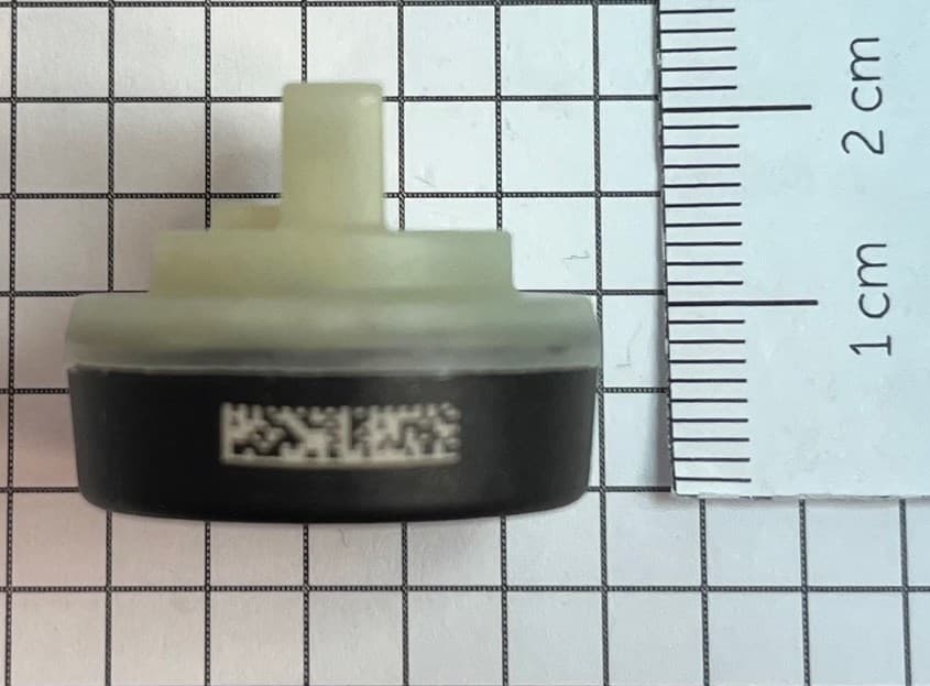
MRXFTMS01
Apr 17, 2024Tyre Pressure Monitor
Equipment Class
DSC - Part 15 Security/Remote Control Transmitter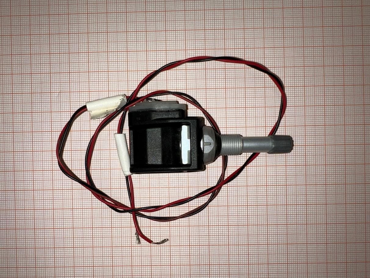
MRXBG6FD4
Jun 27, 2023Tyre Pressure Monitoring Sensor
Equipment Class
DSC - Part 15 Security/Remote Control Transmitter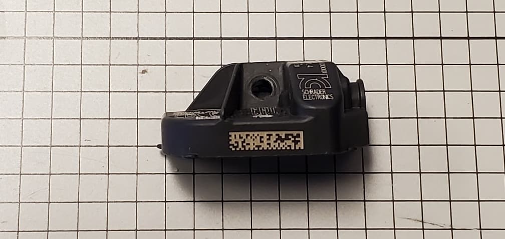
MRXBBFPL4
Mar 26, 2023TPMS Sensor
Equipment Class
DSC - Part 15 Security/Remote Control Transmitter
MRXSCHEB
Jan 25, 2023Tyre Pressure Monitoring System
Equipment Class
DTS - Digital Transmission System
MRXFP4
Aug 30, 2022Tyre Pressure Monitor
Equipment Class
DSC - Part 15 Security/Remote Control Transmitter