MRXT3Tire Pressure Monitoring Transmitter
Schrader Electronics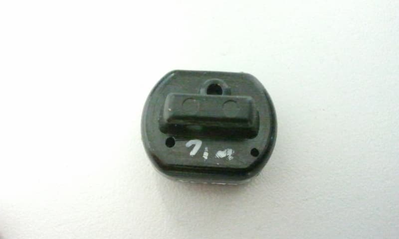
Click to zoom
Application Details
- Equipment Class
- DSC - Part 15 Security/Remote Control Transmitter
- Date of Grant
- Jan 21, 2013
- Application Purpose
- Original Equipment
- Date of Application
- Jan 17, 2013
- Equipment Note
- Tire Pressure Monitoring Transmitter
- Frequency Range
- 314.95400000 - 314.95400000
- Company
- Schrader Electronics
- Country
- Ireland
Documents & Files
Document Text
Text extracted from the exhibit documents filed with the FCC. Open a document above to read the original.
Users Manual
The device under test is manufactured by the grantee (Schrader Electronics) and sold as an OEM product. Per 47 CFR 2.909, 2.927, 2.931, 2.1033, 15.15(b) etc..., the grantee must ensure the end-user has all applicable / appropriate operating instructions. When end-user instructions are required, as in the case of this product, the grantee must notify the OEM to notify the end- user. Schrader Electronics will supply this document to the reseller/distributor dictating what must be included in the end user’s manual for the commercial product. INFORMATION TO BE INCLUDED IN THE END USER'S MANUAL The following information (in blue) must be included in the end product user’s manual to ensure continued FCC and Industry Canada regulatory compliance. The ID numbers must be included in the manual if the device label is not readily accessible to the end user. The compliance paragraphs below must be included in the user's manual. ****************************************************************************** FCC ID: MRXT3 IC: 2546A-T3 This device complies with Part 15 of the FCC Rules and with Licence exempt RSS standards of Industry Canada. Operation is subject to the following two conditions: (1) This device may not cause harmful interference, and (2) This device must accept any interference received, including interference that may cause undesired operation. Le présent appareil est conforme aux CNR d'Industrie Canada applicables aux appareils radio exempts de licence. L'exploitation est autorisée aux deux conditions suivantes: (1) l'appareil ne doit pas produire de brouillage, et (2) l'utilisateur de l'appareil doit accepter tout brouillage radioélectrique subi, même si le brouillage est susceptible d'en compromettre le fonctionnement. WARNING: Changes or modifications not expressively approved by the party responsible for compliance could void the user's authority to operate the equipment. The term “IC:” before the radio certification number only signifies that Industry Canada technical specifications were met. ******************************************************************************
Cover Letter(s)
Manufacturer: Schrader Electronics Subject : FCCIC application documents Dear Sir/Madam I hereby grant authority to Mr James Kyle RF.Approvals Co-ordinator to sign FCCIC .application documents on my behalf. Regards ___________________________ Adrian Condon Project Team Maanager. Oct 31.2012.
Cover Letter(s)
022311 – 6 Authority to Act as Agent Date: __22.Nov.2012______ American Certification Body, Inc. 6731 Whittier Avenue Suite C110 McLean, VA 22101 To Whom It May Concern: COMPLIANCE ENGINEERING IRELAND is authorized to act on our behalf, until otherwise notified, for applications to American Certification Body, Inc. (ACB). We certify that we are not subject to denial of federal benefits, that includes FCC benefits, pursuant to Section 5301 of the Anti-Drug Abuse Act of 1988, 21 U.S.C. 862. Further, no party, as defined in 47 CFR 1.2002 (b), to the application is subject to denial of federal benefits, that includes FCC benefits. Thank you, Agency Agreement Expiration Date: _(Optional)____ By: _____James Kyle_______________ (Signature 1 ) (Print name) Title: RF Approvals Co-ordinator On behalf of: ____Schrader Electronics______________________ (Company Name) Telephone: __02894483067________________________ 1 - Must be signed by applicant contact given for applicant on the FCC site, or by the authorized agent if an appropriate authorized agent letter has been provided. Letters should be placed on appropriate letterhead.
Cover Letter(s)
022311 – 6 Request for Confidentiality Date: ____22.Nov.2012____ Subject: Confidentiality Request for: MRXT3 2546A-T3 Pursuant to FCC 47 CRF 0.457(d) and 0.459 and IC RSP-100, Section 10, the applicant requests that a part of the subject FCC application be held confidential. Type of Confidentiality Requested Exhibit Short Term Permanent*1 Block Diagrams Short Term External Photos Short Term Permanent* 2 Internal Photos Short Term Permanent Operation Description/Theory of Operation Short Term Permanent Parts List & Placement/BOM Short Term Permanent Tune-Up Procedure Short Term Permanent Schematics Short Term Test Setup Photos Short Term Permanent User’s Manual *Note: 1. Block Diagram includes internal oscillator frequency information that the manufacturer considers to be proprietary. *Note: 2. DUT is FULLY potted using a non-removable epoxy based material. Removal of potting material causes irreparable damage to internal circuitry. Photograph exhibits outline the half-clam-shell device before and after potting. Schrader Electronics has spent substantial effort in developing this product and it is one of the first of its kind in industry. Having the subject information easily available to "competition" would negate the advantage they have achieved by developing this product. Not protecting the details of the design will result in financial hardship. Permanent Confidentiality: The applicant requests the exhibits listed above as permanently confidential be permanently withheld from public review due to materials that contain trade secrets and proprietary information not customarily released to the public. Short-Term Confidentiality: The applicant requests the exhibits selected above as short term confidential be withheld from public view for a period of ___(45 ) 3 ___ days from the date of the Grant of Equipment Authorization and prior to marketing. This is to 2 - The asterisked items (*) require further justification before permanent confidentiality will be allowed. These also currently require review by the FCC under their Permit-But-Ask policy before the grant is issued and can delay completion of an application. Further justification should be added to the note above. One such example for a potted device would be: “The EUT is FULLY potted using a non-removable epoxy based material. Removal of potting material causes irreparable damage to internal circuitry. See photographs exhibits that outline the device before and after potting.” 3 - Please refer to http://acbcert.com/documents/misc-docs/Memo-Short-Term-Vs-Standard-Confidentiality.pdf for complete details. 022311 – 6 avoid premature release of sensitive information prior to marketing or release of the product to the public. Applicant is also aware that they are responsible to notify ACB in the event information regarding the product or the product is made available to the public. ACB will then release the documents listed above for public disclosure pursuant to FCC Public Notice DA 04-1705. NOTE for Industry Canada Applications: The applicant understands that until such time that IC distinguishes between Short Term and Permanent Confidentiality, either type of marked exhibit above will simply be marked Confidential when submitted to IC. Sincerely, By: _____James Kyle_______________ (Signature/Title 4 ) (Print name) Title: RF Approvals Co-ordinator 4 - Must be signed by applicant contact given for applicant on the FCC site, or by the authorized agent if an appropriate authorized agent letter has been provided. Letters should be placed on appropriate letterhead.
External Photos
Side Enclosure Top Enclosure Bottom Enclosure
Operational Description
SCHRADER ELECTRONICS.LTD.. EZ TIRE 315 MHZ Product Specification. he TPMS Transmitter is installed to the valve stem in each tyre of a vehicle. The unit measures tyre pressure periodically and transmits this information by RF communication to a receiver inside the vehicle. In addition, the TPMS Transmitter performs the following functions: Determines a temperature compensated pressure value. Determines any abnormal pressure variations in the wheel. Monitors the state of the Transmitters’ internal battery and informs the receiver of a low battery condition. Fig 1: Sensor block diagram EZ TIRE 315 MHZ Block Diagram Pressure Sensor (input) ASIC 32kHz RF Circuit 314.975MHz Loop Antenna Lithium Battery LF Transponder (input) Shock Sensor (input) RF output includes ID, temp, pressure. Extal 9.84256 Mhz Fig 2: Schematic diagram EZ TIRE 315 Mhz Modulation During the Rotating Mode, The modulation used for the sensor is ASK (Amplitude-Shift Keying) with 50% Manchester bi-phase encoding. Modes Rotating Mode While the sensor/transmitter in the Rotating Mode, it shall satisfy the following requirements. The sensor/transmitter shall transmit an instantaneous measured data, if a pressure change of 2.0 psi from the last transmission or greater has occurred with respect to the following conditions. If the pressure change was a decrease of pressure, the sensor/transmitter shall transmit immediately every time it detects the 2.0-psi or greater pressure changes from the last transmission. If the pressure change of 2.0 psi or greater was an increase of pressure, the sensor shall not react to it. Stationary Mode While the sensor/transmitter in the Stationary Mode, it shall satisfy the following requirements. The sensor/transmitter shall transmit an instantaneous measured data, if a pressure change of 2.0 psi from the last transmission or greater has occurred with respect to the following conditions. If the pressure change was a decrease of pressure, the sensor/transmitter shall transmit immediately every time it detects the 2.0-psi or greater pressure changes from the last transmission. If the pressure change of 2.0 psi or greater was an increase of pressure, the silent period between the RPC transmission and the last transmission shall be 30.0 seconds, and the silent period between the RPC transmission and the next transmission (Normal scheduled transmission or another RPC transmission) shall also be 30.0 seconds, to be in compliance of FCC Part 15.231. Factory Mode The factory mode is the mode that the sensor shall transmit more often in the factory to assure the programmability of the sensor ID during the manufacturing process. Off Mode This Off Mode is only for production parts sensors that are used for the builds during the production process and not in the service environment. LF Initiation The sensor/transmitter must provide data upon the presence of an LF signal. The sensor must react (Transmit and provide data) no later than 150.0 ms after the LF data code has been detected at the sensor. The sensor/transmitter must be sensitive (As sensitivity is defined in Table 1) and able to detect the LF field.
Test Report
Report Ref: 12E4186-3a Page 1 of 22 Project Number: 12E4186-3a Prepared for: Schrader Electronics By Compliance Engineering Ireland Ltd Clonross Lane Derrockstown Dunshauhghlin Co. Meath FCC Site Registration: 92592 Industry Canada Assigned Site Code: 8517A-2 FCC ID: MRXT3 IC: 2546A-T3 Date 22 nd November 2012 FCC EQUIPMENT AUTHORISATION Test Report EUT Description Tyre Pressure and Temperature Sensor and Transmitter Module. Authorised : John McAuley Compliance Engineering Ireland Ltd Clonross Lane, Derrockstown, Dunshaughlin, Co. Meath Tel: +353 1 8256722 Fax: +353 1 8256733 Report Ref: 12E4186-3a Page 2 of 22 TEST SUMMARY The equipment complies with the requirements according to the following standards. FCC Part Section(s) RSS-210 Section TEST PARAMETERS Test Result 15.231(a) A1.1.1(a) MAXIMUM MODULATION PERCENTAGE (M%) PASS 15.231(b) A.1.1.2(1) RADIATED EMISSIONS PASS 15.231(c) A1.1.3 20dB BANDWIDTH PASS THIS REPORT SHALL NOT BE REPRODUCED EXCEPT IN FULL, WITHOUT THE WRITTEN APPROVAL OF COMPLIANCE ENGINEERING IRELAND LTD Report Ref: 12E4186-3a Page 3 of 22 Exhibit A – Technical Report Table of Contents 1.0 EUT DESCRIPTION..............................................................................................................................4 1.1 EUT OPERATION..................................................................................................................................5 1.2 MODIFICATIONS...................................................................................................................................5 1.3 DATE OF TEST......................................................................................................................................5 1.4.1 MEASUREMENT UNCERTAINTY.......................................................................................................6 2.0 EMISSIONS MEASUREMENTS............................................................................................................7 2.1 CONDUCTED EMISSIONS MEASUREMENTS...................................................................................7 2.2 RADIATED EMISSIONS MEASUREMENTS.......................................................................................7 2.3 TEST CRITERIA.....................................................................................................................................9 3.0 MAXIMUM MODULATION PERCENTAGE (M%)..............................................................................10 4.0 FIELD STRENGTH OF SPURIOUS RADIATED EMISSIONS..........................................................13 5.0 LIST OF TEST EQUIPMENT...............................................................................................................16 Report Ref: 12E4186-3a Page 4 of 22 1.0 EUT Description The EUT was a module using a short range 315 MHz band transceiver for reporting of tyre pressure and temperature in cars/trucks. Model: T3 Type: 315 MHz Tyre Pressure and Temperature Measurement System FCC ID: MRXT3 Company: Schrader Contact Mr James Kyle Address: Schrader Electronics 11 Technology Park, Belfast Road, Antrim Northern Ireland BT41 1QS Phone: +44 28 9446 3067 e-mail: [email protected] Test Standards: 47 CFR, Part 15.231(a,e) Type of radio: Stand-alone Transmitter Type: ASK Operating Frequency Range(s): 314.954 MHz Number of Channels: One Antenna: Integral Transmitter power configuration: 3 VDC Lithium cell battery. Oper. Temp Range: -40° C to +85° C Classification: DSC Test Methodology: Measurements performed according to the procedures in ANSI C63.4-2003 Report Ref: 12E4186-3a Page 5 of 22 1.1 EUT Operation Operating Conditions during Test: The equipment under test was operated during the measurement under the following conditions: A new battery was used in the EUT for test. The EUT was operated in un-modulated (CW) mode for spurious emissions and radiated power tests. The EUT was operated in EMC mode for modulation bandwidth test. The EUT was operated in normal operation (roll mode) for the duty cycle test. Environmental conditions During the measurement the environmental conditions were within the listed ranges: Normal Temperature: +15 to +35 ° C Humidity: 20-75 % 1.2 Modifications No modifications were required in order to pass the test specifications. 1.3 Date of Test The tests were carried out on one sample of the EUT during the month of October 2012. Report Ref: 12E4186-3a Page 6 of 22 1.4 Electromagnetic Emissions Testing The guidelines of CISPR 16-4 were used for all uncertainty calculations, estimates and expressions thereof for EMC testing. A copy of Compliance Engineering Ireland Ltd.’s policy for EMC Measurement Uncertainty is available on request. RF Requirements: Spurious emissions in accordance with FCC CFR 15.107, 15.109 and 15.209. Tests were carried out to the requirements of CISPR 16-4 and ANSI C63.4-2009. 1.4.1 Measurement Uncertainty The measurement uncertainty (with a 95% confidence level) for the conducted emissions test was ±3.5 dB. The measurement uncertainty (with a 95% confidence level) for the radiated emissions test was ±5.3 dB (from 30 to 100 MHz), ±4.7 dB (from 100 to 300 MHz), ±3.9 dB (from 300 to 1000 MHz) and ±3.8 dB (from 1 GHz to 40 GHz). Report Ref: 12E4186-3a Page 7 of 22 2.0 Emissions Measurements 2.1 Conducted Emissions Measurements Test not performed as EUT is powered from 3 volt battery. 2.2 Radiated Emissions Measurements Radiated Power measurements were made at the Compliance Engineering Ireland Ltd anechoic chamber located in Dunshaughlin, Co. Meath, Ireland to determine the radio noise radiated from the EUT. A "Description of Measurement Facilities" has been submitted to the FCC and approved pursuant to Section 2.948 of CFR 47 of the FCC rules. The EUT was centred on a motorized turntable, which allows 360 degree rotation. A measurement antenna was positioned at a distance of 3 meters as measured from the closest point of the EUT. The radiated emissions were maximi…
Text truncated - open the document above for the full version.
Test Setup Photos
Test Set up Fig 1Test setup Fig 2 Test setup Fig 3 Test setup
Contact Information
Applicant
James Kyle
Technical Contact
Test Firm
Compliance Engineering Ireland Ltd.John McAuley
Technical Specifications
| # | Rule Parts | Frequency Range | Power Output |
|---|---|---|---|
| 1 | 15.231(e) | 314.954 MHz - 314.954 MHz | - |
Other Applications from Schrader Electronics
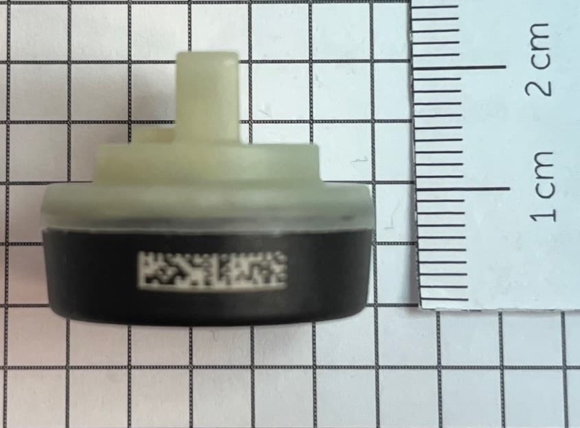
MRXFTMS01
Apr 17, 2024Tyre Pressure Monitor
Equipment Class
DSC - Part 15 Security/Remote Control Transmitter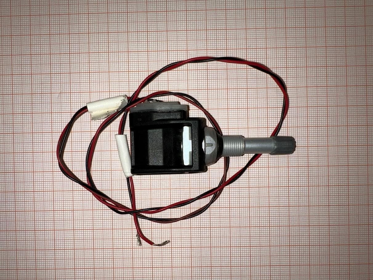
MRXBG6FD4
Jun 27, 2023Tyre Pressure Monitoring Sensor
Equipment Class
DSC - Part 15 Security/Remote Control Transmitter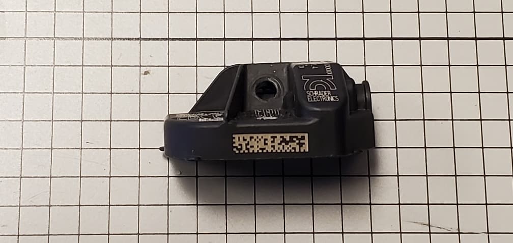
MRXBBFPL4
Mar 26, 2023TPMS Sensor
Equipment Class
DSC - Part 15 Security/Remote Control Transmitter
MRXSCHEB
Jan 25, 2023Tyre Pressure Monitoring System
Equipment Class
DTS - Digital Transmission System
MRXFP4
Aug 30, 2022Tyre Pressure Monitor
Equipment Class
DSC - Part 15 Security/Remote Control Transmitter