MRXTG315AM04Remote Tyre Pressure Monitoring Transmitter
Schrader Electronics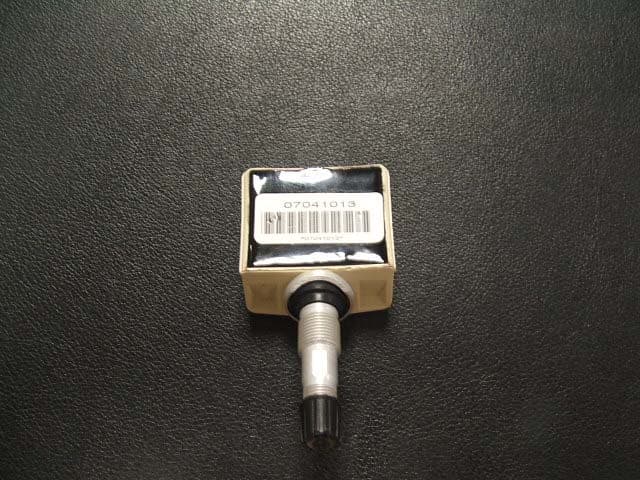
Click to zoom
Application Details
- Equipment Class
- DSC - Part 15 Security/Remote Control Transmitter
- Date of Grant
- May 29, 2006
- Application Purpose
- Original Equipment
- Date of Application
- May 29, 2006
- Equipment Note
- Remote Tyre Pressure Monitoring Transmitter
- Frequency Range
- 315.00000000 - 315.00000000
- Company
- Schrader Electronics
- Country
- Ireland
Documents & Files
Document Text
Text extracted from the exhibit documents filed with the FCC. Open a document above to read the original.
Users Manual
11 Technology Pk, Belfast Rd, Antrim, BT41 1QS, Northern Ireland Tel: +44 2894 482000 Fax : +44 2894 468440 RE: Certification for Schrader Electronics Ltd Remote Tyre Pressure Transmitter Model: MRXTG315AM04 FCC ID: MRXTG315AM04 Canada ID: 2546A – 1022004 USERS MANUAL The manual is not available at this time. The following material will be contained in the vehicle owners manual: This device complies with Part 15 of the FCC rules and with RSS-210 of Industry Canada. Operation is subject to the following two conditions : (1) This device may not cause harmful interference, and (2) This device must accept any interference received, including interference that my cause undesired operation. WARNING : Changes or modifications not expressively approved by the party responsible for compliance could void the user’s authority to operate the equipment.
Block Diagram
Technical Description of the transmitter type FCC : MRXTG315AM04 IC : 2546A – 1022004 Equipment Characteristics Type Transmitter Trade mark Schrader Frequency Range 315 MHz Fixed ± 100kHz Xtal Frequency 32.768 kHz Method of Carrier Frequency Generation SAW stabilised oscillator Class of Emission A1D Type of Modulation ASK Modulation Signal Input Level N/A Modulation Bandwidth 4KHz Number of Channels 1 Utilisation Mobile Duplex operation No Antenna Integral Alternative Antenna No Operating Temperature Range -40°C to +100°C Rated Output Power -30.2dBm (1μW) Voltage supply range 2.5 to 3.3 V DC Composition of Equipment Single Unit Brief Description A block diagram of the RTPMS is shown in figure 1. The transmitter has the following sections: - RF circuit - Pressure sensor - roll switch - Transponder Coil (125kHz LF Learn Switch) - ASIC The system has been developed to monitor a vehicle's tyre pressures whilst driving or stationary. An electronic unit inside each tyre, (referred to as the RTPMS transmitter) mounted to the valve stem, periodically measures actual tyre pressure. By means of RF communication, this pressure information is transmitted to a receiver/decoder which is fitted in the car. The tire pressure value is detected by the ASIC (Application Specific Integrated Circuit) via a pressure sensor. The data is transmitted using a Manchester coding protocol at a maximum data rate of 4.096 Kbits/sec. The clock generator for the ASIC is crystal controlled. The block transmission format is shown in figure 2. The valve stem is part of the transmitting antenna. while the vehicle is parked (Stationary Mode), there is no transmission. when the vehicle is moving (roll switch closed) the RTPMS transmit each minute 8 words as shown in figure 2. The transmitter will remain in drive mode for a period of time known as the Service Period after the vehicle comes to rest (roll switch open). After the Service Period time has elapsed the transmitter returns to Stationary Mode. The RTPMS uses a Transponder Coil, which when activated with 125kHz LF, will ‘LEARN’ the ID code to the receiver/decoder in the production line of the vehicles. Page 3 of 4 ROLL RF CIRCUIT ASIC 3V LITHIUM BATTERY VALVE LEARN PRESSURE SENSOR Fig.1 Page 4 of 4 6 x 25 ms B = 0.15 s 8 words ( 1 block) < 1 second 18 Bits of Start 3 Bits 24 Bits 8 Bits 2 Bits 1 Word or Frame width = 13.4 ms ± 1% B Fig.2
Operational Description
Technical Description of the transmitter type FCC : MRXTG315AM04 IC : 2546A – 1022004 Equipment Characteristics Type Transmitter Trade mark Schrader Frequency Range 315 MHz Fixed ± 100kHz Method of Carrier Frequency Generation SAW stabilised oscillator Class of Emission A1D Type of Modulation ASK Modulation Signal Input Level N/A Modulation Bandwidth 4KHz Number of Channels 1 Utilisation Mobile Duplex operation No Antenna Integral Alternative Antenna No Operating Temperature Range -40°C to +100°C Rated Output Power -30.2dBm (1μW) Voltage supply range 2.5 to 3.3 V DC Composition of Equipment Single Unit Brief Description A block diagram of the RTPMS is shown in figure 1. The transmitter has the following sections: - RF circuit - Pressure sensor - roll switch - Transponder Coil (125kHz LF Learn Switch) - ASIC The system has been developed to monitor a vehicle's tyre pressures whilst driving or stationary. An electronic unit inside each tyre, (referred to as the RTPMS transmitter) mounted to the valve stem, periodically measures actual tyre pressure. By means of RF communication, this pressure information is transmitted to a receiver/decoder which is fitted in the car. The tire pressure value is detected by the ASIC (Application Specific Integrated Circuit) via a pressure sensor. The data is transmitted using a Manchester coding protocol at a maximum data rate of 4.096 Kbits/sec. The clock generator for the ASIC is crystal controlled. The block transmission format is shown in figure 2. The valve stem is part of the transmitting antenna. while the vehicle is parked (Stationary Mode), there is no transmission. when the vehicle is moving (roll switch closed) the RTPMS transmit each minute 8 words as shown in figure 2. The transmitter will remain in drive mode for a period of time known as the Service Period after the vehicle comes to rest (roll switch open). After the Service Period time has elapsed the transmitter returns to Stationary Mode. The RTPMS uses a Transponder Coil, which when activated with 125kHz LF, will ‘LEARN’ the ID code to the receiver/decoder in the production line of the vehicles. Page 3 of 4 ROLL RF CIRCUIT ASIC 3V LITHIUM BATTERY VALVE LEARN PRESSURE SENSOR Fig.1 Page 4 of 4 6 x 25 ms B = 0.15 s 8 words ( 1 block) < 1 second 18 Bits of Start 3 Bits 24 B its 8 Bits 2 Bits 1 Word or Frame width = 13.4 ms ± 1% B Fig.2
Schematics
1 2 3 4 56 ABCD 6 5 4 3 2 1 D CBA ISSUE DESCRIPTION ECN DATE DRAWN CHECKED APPROVED DATE TITLE DRAWING No. _ _ _ _ _ _ _ _ PART OF _ _ _ _ _ _ _ _ _ _ SHEET _ _ OF _ _ C1 C2 C3 C4 C5 C6 C7 C8 C9 C10 C11C12 C13 C14 C15 C16 C17 C18 R1 R2 R3 R4 R6 R7 R8 R9 R10 L1 C20 L2 R17 L3 Q1 Q2 ROLLREEDN/C C19 TPOND3v VFUSE FUSENRFDATAGROUND VDOUBLE RES315MHz XTAL32.768kHz 1 1 VOLVO RTPMS SW2 BATTERY Power 1 1 2 2 3 3 4 4 5 5 6 6 7 7 8 8 U3SENSOR1 U2 R18 R5 + + TPND* COMB_TRANSPONDER REED REED TPOND TPOND IREF 26 VSS 20 VDOUBLE 21 ADCIN 1 OVA 4 TEST2 8 SENSE1 5 REED 27 TPOND 28 VDD 24 CAP1 23 VREG 19 VRF 18 CAP2 22 ADCOUT 3 ADCMID 2 TEST1 7 SENSE2 6 TEST3 9 TILT 10 ROLL 11 OSC1 12 OSC2 13 VFUSE 14 FUSEN 15 RFENABLE 16 RFDATA 17 IFREFSNS 25 U1 ASIC GEN 2 MLP Volvo 315 AM Tx Volvo 01 Prototype Release XXXX 02 MLP ASIC Replaced With SSOP XXXX 05/06/0322/07/03 03 Initial Production Release 0731 19/11/03 90509049
Test Report
Schrader Electronics Ltd FCC Part 15 – Volvo 315 AM Tyre Sensor MIRA-1012122 Summary Page 2 of 7 SUMMARY A Schrader Electronics Ltd Volvo 315 AM Tyre Sensor Transmitter was tested in accordance with FCC Part 15, Subpart C and with RSS-210 of Industry Canada. The Schrader Electronics Ltd Volvo 315 AM Tyre Sensor Transmitter met the limits for radiated emissions by 6.8 dB and by 3.9 dB at the harmonics. Beside the harmonics there were no other significant spurious emissions located. The test results contained within relate only to the sample(s) identified in this report. Schrader Electronics Ltd FCC Part 15 – Volvo 315 AM Tyre Sensor MIRA-1012122 Contents Page 3 of 7 CONTENTS Page 1 Introduction...................................................................................................................4 2 Configuration and Equipment Under Test (EUT) Details ..........................................4 3 Radiated Emissions......................................................................................................5 3.1 Test Method....................................................................................................................5 3.2 Test Conditions...............................................................................................................5 3.3 Test Limits and Computations ........................................................................................5 3.4 Test Results ....................................................................................................................6 4 Conducted Emissions ..................................................................................................7 5 Other Measurements and Computations ...................................................................7 5.1 Correction for Pulse Operation .......................................................................................7 5.2 Bandwidth .......................................................................................................................7 6 Conclusions ..................................................................................................................7 Table 3.3.1 - Radiated Emission Limits Data Transmission ....................................................6 Table 3.3.2 - Radiated Emission Limits Digital Class B ...........................................................6 Table 3.4 - Highest Radiated Emissions Measured .................................................................6 Appendix A Test Equipment Appendix B EUT Photographs Appendix C Test Results Schrader Electronics Ltd FCC Part 15 – Volvo 315 AM Tyre Sensor MIRA-1012122 Page 4 of 7 1 Introduction A Schrader Electronics Ltd Volvo 315 AM Tyre Sensor Transmitter was tested for compliance in accordance with FCC Regulations, part 15, adopted under Docket 87-389, April 18, 1989 and with Industry Canada RSS-210, Issue 5, dated November 1, 2001. The tests were performed at MIRA Ltd Open Area Test Site following the procedures described in ANSI C63.4-1992 “Methods of Measurements of Radio-Noise Emissions from Low-Voltage Electrical and Electronic Equipment in the Range of 9 kHz to 40 GHz’. The Schrader Electronics Ltd Volvo 315 AM Tyre Sensor Transmitter MRXTG315AM04 was received at MIRA on 03/04/06. Tests were performed on 03/04/06 and 12/04/06. All equipment was returned to Schrader Electronics Ltd on 26/04/06. No representative was present to witness the testing on behalf of Schrader Electronics Ltd. The site description and attenuation characteristics of MIRA Ltd Open Area Test Site are on file with FCC Laboratory, Columbia, Maryland, USA (registration number 877566) and with Industry Canada, Ottawa, ON (File Ref. No: IC 6001). 2 Configuration and Equipment Under Test (EUT) Details The EUT is a 3.5 x 7.0 x 1.5 cm size (including value stem) potted tyre pressure sensor/transmitter that mounts on a rim inside the tyre. When the vehicle is in motion, the EUT transmits tyre pressure information to the receiver in the vehicle. The transmission consists of eight ASK encoded words of total duration of 0.928 seconds which repeat typically every 63 seconds. The 315 MHz carrier is generated by a SAW stabilised oscillator. The coding is performed by an ASCI timed by a 32.768 kHz crystal oscillator. • Manufacturer Schrader Electronics Ltd • EUT ID: Schrader Remote Tyre Pressure Monitoring Transmitter • Model: Volvo 315 AM Tyre Sensor • Serial Number: No Number on EUT • ITU Emission Code 300KK1DAN • FCC ID: MRXTG315AM04 • IC ID: 2564A-1022004 • MIRA IDs: E206-0185 & E206-0186 Two samples were provided; these consisted of a continuous sample used to maximise the emissions and a standard sample to be used for the pulse emission, correction for pulse operation and bandwidth measurements. Schrader Electronics Ltd FCC Part 15 – Volvo 315 AM Tyre Sensor MIRA-1012122 Page 5 of 7 3 Radiated Emissions The radiated emissions tests were carried out on the Open Area Test Site (OATS) at MIRA in accordance with FCC Regulation 47, Subpart C, Section 15.231 and ANSI Standard C63.4- 1992 standard. 3.1 Test Method The EUT was tested as a standalone unit (i.e. not mounted on a tyre rim) The tests were performed on the EUT over the frequency range 30 MHz to the tenth harmonic of the EUT 315 MHz fundamental. This involved measuring the emissions from the EUT using an antenna, turntable and a receiver system. The EUT was placed on a 1 m by 1.5 m, 0.8 m table. Photographs showing the test configuration are shown in Appendix B. Tests were conducted using both the vertical and horizontal polarisations of the antenna. Peak readings were taken in three orthogonal EUT planes (see figure 3.1). The highest readings were converted to average readings based on the duration of the EUT ‘on’ time. When an emission was located, the table was rotated to maximise the signal strength. When this signal strength was determined, the test antenna was raised and lowered from 1 m to 4 m t…
Text truncated - open the document above for the full version.
Contact Information
Applicant
James Kyle
Technical Contact
Non-Technical Contact
Mira LtdSteven Clegg
[email protected]+44 2476 355422
Test Firm
MIRA LtdSteven Clegg
Technical Specifications
| # | Rule Parts | Frequency Range | Power Output |
|---|---|---|---|
| 1 | 15.231(e) | 315 MHz - 315 MHz | - |
Other Applications from Schrader Electronics
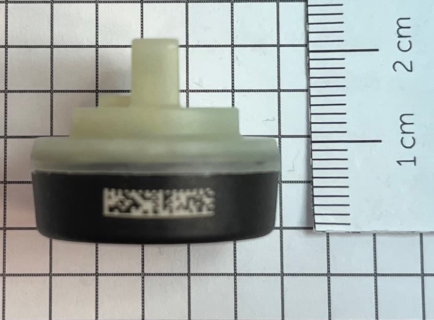
MRXFTMS01
Apr 17, 2024Tyre Pressure Monitor
Equipment Class
DSC - Part 15 Security/Remote Control Transmitter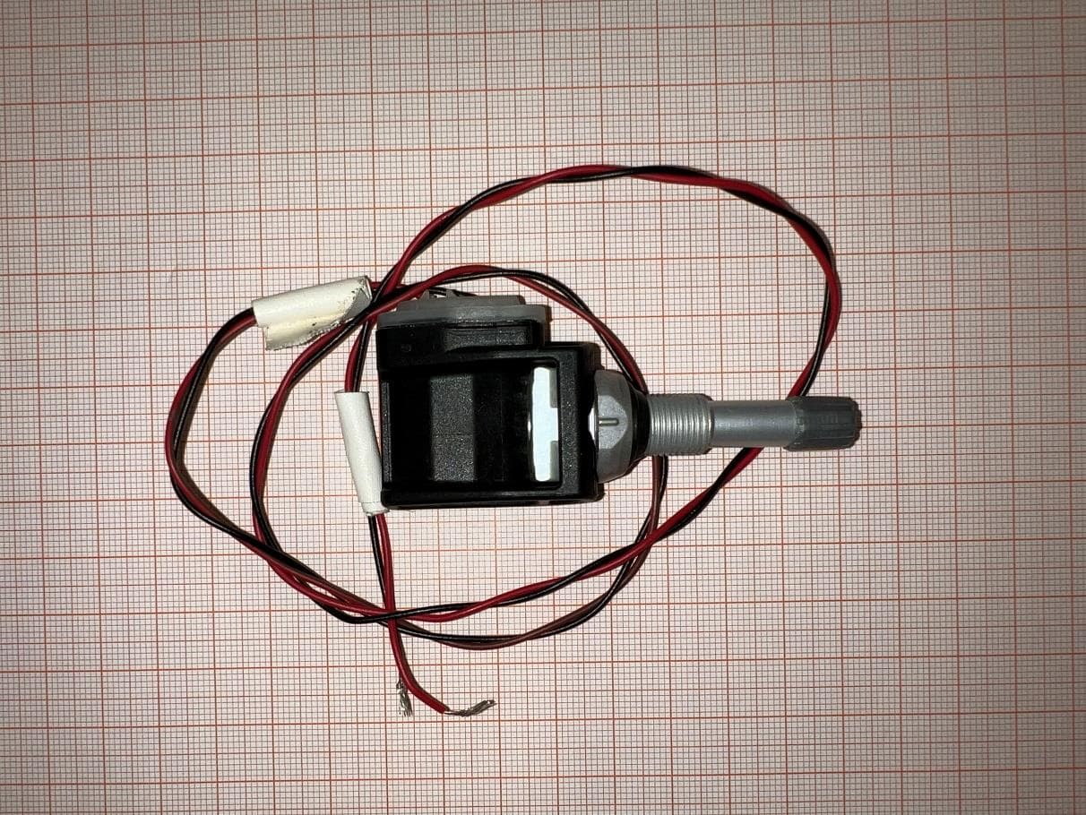
MRXBG6FD4
Jun 27, 2023Tyre Pressure Monitoring Sensor
Equipment Class
DSC - Part 15 Security/Remote Control Transmitter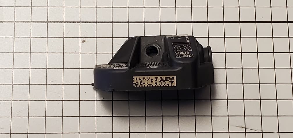
MRXBBFPL4
Mar 26, 2023TPMS Sensor
Equipment Class
DSC - Part 15 Security/Remote Control Transmitter
MRXSCHEB
Jan 25, 2023Tyre Pressure Monitoring System
Equipment Class
DTS - Digital Transmission System
MRXFP4
Aug 30, 2022Tyre Pressure Monitor
Equipment Class
DSC - Part 15 Security/Remote Control Transmitter