MSQ-RTN66UDark Knight Double 450Mbps Dual N Band
ASUSTeK Computer Inc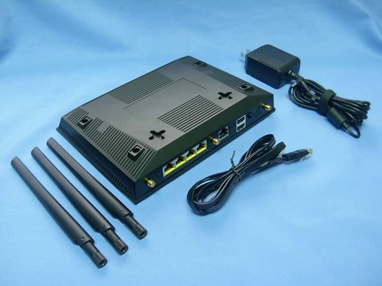
Click to zoom
Application Details
- Equipment Class
- DTS - Digital Transmission System
- Date of Grant
- Dec 06, 2011
- Application Purpose
- Original Equipment
- Date of Application
- Nov 26, 2011
- Equipment Note
- Dark Knight Double 450Mbps Dual N Band
- Frequency Range
- 5755.00000000 - 5795.00000000
- Company
- ASUSTeK Computer Inc
- Country
- Taiwan
Documents & Files
Document Text
Text extracted from the exhibit documents filed with the FCC. Open a document above to read the original.
Users Manual
Quick Start Guide RT-N66U Dark Knight Gigabit Router Wireless-N900 ® E7019 / Second Edition / November 2011 EC Declaration of Conformity We, the undersigned, Manufacturer: ASUSTek COMPUTER INC. Address, City: No. 150, LI-TE RD., PEITOU, TAIPEI 112, TAIWAN R.O.C. Country: TAIWAN Authorized representative in Europe: ASUS COMPUTER GmbH Address, City: HARKORT STR. 21-23, 40880 RATINGEN Country: GERMANY declare the following apparatus: Product name : Dark Knight Double 450Mbps Dual N Band Router Model name : RT-N66U conform with the essential requirements of the following directives: 2004/108/EC-EMC Directive EN 55022:2006+A1:2007 Class B EN 61000-3-2:2006+A2:2009 Class A EN 55024:1998+A1:2001+A2:2003 EN 61000-3-3:2008 1999/5/EC-R &TTE Directive EN 300 328 V1.7.1(2006-10) EN 301 893 V1.5.1(2008-12) EN 62311:2008 EN 301 489-1 V1.8.1(2008-04) EN 301 489-17 V2.1.1(2009-05) 2006/95/EC-LVD Directive EN 60950-1:2006 EN 60950-1:2006+A11:2009 EN 60065:2002+A1:2006+A11:2008 2009/125/EC-ErP Directive Regulation (EC) No. 1275/2008 EN 62301:2005 Regulation (EC) No. 642/2009 EN 62301:2005 Regulation (EC) No. 278/2009 EN 62301:2005 Ver. 110101 CE marking Declaration Date: Nov. 1, 2011 Year to begin affixing CE marking:2011 Position : CEO Name : Jerry Shen Signature :__________ (ECconformity marking) NOTE / <T-CHINESE> / <FRENCH> / <PORTUGUESE> / <SPANISH> • For more details, refer to the user manual included in the support CD. • <T-CHINESE> • <FRENCH> • <PORTUGUESE> • <SPANISH> Table of contents English .............................................................................................4 T-Chinese ........................................................................................17 French ..............................................................................................30 Portuguese ....................................................................................43 Spanish ............................................................................................56 4 English Package contents RT-N66U AC adapter Network cable Quick Start Guide Support CD (User Manual/utilities) Warranty card Stand A quick look 1) Power LED5) 5GHz LED9) USB 2.0 ports 2) LAN LED6) USB 2.0 LED10) Reset button 3) WAN LED7) Power (DC-In) port11) Internet & LAN ports 4) 2.4GHz LED8) Power switch12) WPS button NOTE: If any of the items is damaged or missing, contact your retailer. 791012 11 8 12 3 5 6 4 5 English NOTES: • USB External HDD/Flash disk: • The wireless router works with most USB HDDs/Flash disks up to 2TB and supports read-write access for FAT16, FAT32, EXT2, EXT3, and NTFS. • To safely remove the USB disk, launch the web GUI (http://192.168.1.1), then in the Network Map page's upper right corner, click the USB icon and click Eject USB 1. • Incorrect removal of the USB disk may cause data corruption. • For the list of file system and hard disk partitions that the wireless router supports, visit http://event.asus.com/networks/ disksupport • For the list of printers that the wireless router supports, visit http://event.asus.com/networks/printersupport 6 Positioning your wireless router For the best wireless signal transmission between the wireless router and the network devices connected to it, ensure that you: • Place the wireless router in a centralized area for a maximum wireless coverage for the network devices. • Keep the device away from metal obstructions and away from direct sunlight. • Keep the device away from 802.11g or 20MHz only Wi-Fi devices, 2.4GHz computer peripherals, Bluetooth devices, cordless phones, transformers, heavy-duty motors, fluorescent lights, microwave ovens, refrigerators, and other industrial equipment to prevent signal interference or loss. • To ensure the best wireless signal, orient the three detachable antennas as shown in the drawing below. • For optimum performance, adjust the internal cooling system. Refer to the user manual for details. • Always update to the latest firmware. Visit the ASUS website at http://www.asus.com to get the latest firmware updates. 45 0 45 0 90 0 English 7 Mounting to the stand • Align and insert the stand’s mounting hooks to the wireless router’s mounting holes. Before you proceed 1. Unplug and disconnect the wires/cables from your existing modem setup and release your computer’s outmoded IP address. a: Unplug the AC adapter from the power outlet and disconnect it from your cable/ADSL modem. b: Disconnect the network cable from your cable/ADSL modem. c: Reboot your computer (recommended). Modem OFF ! a b c English 8 WARNING! Before disconnecting the wires/cables, ensure that your cable/ADSL modem has been turned off for at least two minutes. If your modem has a backup battery, remove it as well. 2. Set up your wireless environment. RT-N66U Computer Modem LAN Power Wall Power Outlet Power WAN a b c d a: Insert your wireless router’s AC adapter to the DC-In port and plug it to a power outlet. b: Using the bundled network cable, connect your computer to your wireless router’s LAN port. IMPORTANT! Ensure that the WAN and LAN LEDs are blinking. c: Using another network cable, connect your modem to your wireless router’s WAN port. d: Insert your modem’s AC adapter to the DC-In port and plug it to a power outlet. English 9 3. Disable some settings on your computer. A. Disable the proxy server, if enabled. B. Set the TCP/IP settings to automatically obtain an IP address. C. Disable the dial-up connection, if enabled. NOTE: For more details on disabling your computer settings, refer to Frequently Asked Questions (FAQs). 1. Configure your wireless settings via the wireless router’s web graphics user interface (web GUI). a: Launch your web browser such as Internet Explorer, Firefox, Google Chrome, or Safari. Getting started b a English 10 NOTE: If QIS does not launch automatically, follow these steps to manually launch QIS: • On your web browser, key in http://192.168.1.1 and run the Quick Internet Setup (QIS) Wizard again. • Disable the…
Text truncated - open the document above for the full version.
External Photos
Report No: 116286R-RFUSP42V01 Page: 284 of 290 Attachement EUT Photograph (1) EUT Photo (2) EUT Photo
ID Label/Location Info
Model: RT-N66U Dark Knight Double 450Mbps Dual N Band Router Input: DC 19V 1.58A ASUS RT-N66U FCC ID:MSQ-RTN66U Factory Default setting: IP Address:192.168.1.1 User name:admin Password:admin SSID:ASUS Change your password ASAP Complies with IDA Standards DB101867 IC: 3568A-RTN66U N13219 ASUSTek Computer Inc.Made in China
ID Label/Location Info
ASUSTeK COMPUTER INC. No. 15, Li-Te Rd., Peitou, Taipei 112, Taiwan R.O.C. FCC ID.: MSQ- MSQ-RTN66U FCC ID AND DoC Label
Internal Photos
Report No: 116286R-RFUSP42V01 Page: 285 of 290 (3) EUT Photo (4) EUT Photo Report No: 116286R-RFUSP42V01 Page: 286 of 290 (5) EUT Photo (6) EUT Photo Report No: 116286R-RFUSP42V01 Page: 287 of 290 (7) EUT Photo (8) EUT Photo Report No: 116286R-RFUSP42V01 Page: 288 of 290 (9) EUT Photo (10) EUT Photo Report No: 116286R-RFUSP42V01 Page: 289 of 290 (11) EUT Photo Report No: 116286R-RFUSP42V01 Page: 290 of 290 (12) EUT Photo (ANT)
RF Exposure Info
Report No. 116286R-RF-US-Exp Page: 1 of 7 RF Exposure Evaluation declaration Product Name : Dark Knight Double 450Mbps Dual N Band Router Model No. : RT-N66U FCC ID. : MSQ-RTN66U Applicant : ASUSTeK COMPUTER INC. Address : No. 15, Li-Te Rd., Peitou, Taipei 112, Taiwan R.O.C. Date of Receipt : 2011/06/17 Date of Declaration : 2011/11/22 Report No. : 116286R-RF-US-Exp Report Version : V1.0 The declaration results relate only to the samples calculated. The declaration shall not be reproduced except in full without the written approval of QuieTek Corporation. Report No. 116286R-RF-US-Exp Page: 2 of 7 1. RF Exposure Evaluation 1.1. Limits According to FCC 1.1310: The criteria listed in the following table shall be used to evaluate the environment impact of human exposure to radio frequency (RF) radiation as specified in 1.1307(b) LIMITS FOR MAXIMUM PERMISSIBLE EXPOSURE (MPE) Frequency Range (MHz) Electric Field Strength (V/m) Magnetic Field Strength (A/m) Power Density (mW/cm 2 ) Average Time (Minutes) (A) Limits for Occupational/ Control Exposures 300-1500 -- -- F/300 6 1500-100,000 -- -- 5 6 (B) Limits for General Population/ Uncontrolled Exposures 300-1500 -- -- F/1500 6 1500-100,000 -- -- 1 30 F= Frequency in MHz Friis Formula Friis transmission formula: Pd = (Pout*G)/(4*pi*r 2 ) Where Pd = power density in mW/cm 2 Pout = output power to antenna in mW G = gain of antenna in linear scale Pi = 3.1416 R = distance between observation point and center of the radiator in cm Pd id the limit of MPE, 1 mW/cm 2 . If we know the maximum gain of the antenna and the total power input to the antenna, through the calculation, we will know the distance r where the MPE limit is reached. 1.2. Test Procedure Software provided by client enabled the EUT to transmit and receive data at lowest, middle and highest channel individually. The temperature and related humidity: 18°Cand 78% RH. Report No. 116286R-RF-US-Exp Page: 3 of 7 1.3. Test Result of RF Exposure Evaluation Product Dark Knight Double 450Mbps Dual N Band Router Test Mode Mode 1: Transmit Test Condition RF Exposure Evaluation Antenna Gain Antenna Gain: The maximum Gain measured in fully anechoic chamber is 2dBi or 1.58 in linear scale. Output Power into Antenna & RF Exposure Evaluation Distance: IEEE 802.11b WLAN Function Channel Channel Frequency (MHz) Output Power to Antenna (mW) Power Density at R = 20 cm (mW/cm 2 ) 1 2412 251.7677 0.07914 6 2437 297.8516 0.09362 11 2462 163.3052 0.05133 IEEE 802.11g WLAN Function Channel Channel Frequency (MHz) Output Power to Antenna (mW) Power Density at R = 20 cm (mW/cm 2 ) 1 2412 423.6430 0.13316 6 2437 424.6196 0.13347 11 2462 406.4433 0.12776 The power density Pd (4th column) at a distance of 20 cm calculated from the Friis transmission formula is far below the limit of 1 mW/cm 2 . Report No. 116286R-RF-US-Exp Page: 4 of 7 Product Dark Knight Double 450Mbps Dual N Band Router Test Mode Mode 1: Transmit Test Condition RF Exposure Evaluation Antenna Gain Antenna Gain: The maximum Gain measured in fully anechoic chamber is 2dBi or 1.58 in linear scale. Output Power into Antenna & RF Exposure Evaluation Distance: IEEE 802.11n (20MHz) WLAN Function Channel Channel Frequency (MHz) Output Power to Antenna (mW) Power Density at R = 20 cm (mW/cm 2 ) 1 2412 997.7001 0.31361 6 2437 952.7962 0.29949 11 2462 727.7798 0.22876 IEEE 802.11n (40MHz) WLAN Function Channel Channel Frequency (MHz) Output Power to Antenna (mW) Power Density at R = 20 cm (mW/cm 2 ) 3 2422 818.4648 0.25727 6 2437 716.1434 0.22511 9 2452 584.7901 0.18382 The power density Pd (4th column) at a distance of 20 cm calculated from the Friis transmission formula is far below the limit of 1 mW/cm 2 . Report No. 116286R-RF-US-Exp Page: 5 of 7 Product Dark Knight Double 450Mbps Dual N Band Router Test Mode Mode 1: Transmit Test Condition RF Exposure Evaluation Antenna Gain Antenna Gain: The maximum Gain measured in fully anechoic chamber is 2dBi or 1.58 in linear scale. Output Power into Antenna & RF Exposure Evaluation Distance: IEEE 802.11a WLAN Function Channel Channel Frequency (MHz) Output Power to Antenna (mW) Power Density at R = 20 cm (mW/cm 2 ) 36 5180 45.8142 0.01440 40 5220 45.4988 0.01430 44 5240 42.8549 0.01347 IEEE 802.11a WLAN Function Channel Channel Frequency (MHz) Output Power to Antenna (mW) Power Density at R = 20 cm (mW/cm 2 ) 149 5745 550.8077 0.17314 153 5785 553.3501 0.17393 165 5825 539.5106 0.16958 The power density Pd (4th column) at a distance of 20 cm calculated from the Friis transmission formula is far below the limit of 1 mW/cm 2 . Report No. 116286R-RF-US-Exp Page: 6 of 7 Product Dark Knight Double 450Mbps Dual N Band Router Test Mode Mode 1: Transmit Test Condition RF Exposure Evaluation Antenna Gain Antenna Gain: The maximum Gain measured in fully anechoic chamber is 2dBi or 1.58 in linear scale. Output Power into Antenna & RF Exposure Evaluation Distance: IEEE 802.11 n(20MHz) WLAN Function Channel Channel Frequency (MHz) Output Power to Antenna (mW) Power Density at R = 20 cm (mW/cm 2 ) 36 5180 33.8844 0.01065 40 5220 33.2660 0.01046 44 5240 31.3329 0.00985 IEEE 802.11 n(20MHz) WLAN Function Channel Channel Frequency (MHz) Output Power to Antenna (mW) Power Density at R = 20 cm (mW/cm 2 ) 149 5745 783.4296 0.24626 153 5785 809.0959 0.25432 165 5825 833.6812 0.26205 The power density Pd (4th column) at a distance of 20 cm calculated from the Friis transmission formula is far below the limit of 1 mW/cm 2 . Report No. 116286R-RF-US-Exp Page: 7 of 7 Product Dark Knight Double 450Mbps Dual N Band Router Test Mode Mode 1: Transmit Test Condition RF Exposure Evaluation Antenna Gain Antenna Gain: The maximum Gain measured in fully anechoic chamber is 2dBi or 1.58 in linear scale. Output Power into Antenna & RF Exposure Evaluation Distance: IEEE 802.11 n(40MHz) WLAN Function Channel Channel Frequency (MHz) Output Power to Antenna (mW) Power Density at R = 20 cm (mW/cm 2 ) 38 5190 38.9045 0.01223 46 5230 32.5837 0.01024 IEEE 802…
Text truncated - open the document above for the full version.
Test Report
Report No: 116286R-RFUSP42V01 Page: 1 of 290 Test Report Product Name : Dark Knight Double 450Mbps Dual N Band Router Model No. : RT-N66U FCC ID. : MSQ-RTN66U Applicant : ASUSTeK COMPUTER INC. Address : No. 15, Li-Te Rd., Peitou, Taipei 112, Taiwan R.O.C. Date of Receipt:2011/06/17 Issued Date :2011/11/22 Report No. :116286R-RFUSP42V01 Report Version :V1.0 The test results relate only to the samples tested. The test report shall not be reproduced except in full without the written approval of QuieTek Corporation. Report No: 116286R-RFUSP42V01 Page: 2 of 290 Test Report Certification Issued Date : 2011/11/22 Report No. : 116286R-RFUSP42V01 Product Name : Dark Knight Double 450Mbps Dual N Band Router Applicant : ASUSTeK COMPUTER INC. Address : No. 15, Li-Te Rd., Peitou, Taipei 112, Taiwan R.O.C. Manufacturer : Askey Technology (Jiangsu) LTD. Model No. : RT-N66U FCC ID. : MSQ-RTN66U EUT Voltage : AC 100-240V, 50-60Hz Trade Name : ASUS Applicable Standard : FCC CFR Title 47 Part 15 Subpart C Section 15.247:2010 ANSI C63.4: 2009 Test Result : Complied The test results relate only to the samples tested. The test report shall not be reproduced except in full without the written approval of QuieTek Corporation. Documented By : (Sandy Chuang / Adm. Specialist) Reviewed By : ( Ben Huang / Engineer ) Approved By : ( Roy Wang / Manager ) Report No: 116286R-RFUSP42V01 Page: 3 of 290 TABLE OF CONTENTS Description Page 1. General Information.............................................................................................................. 5 1.1. EUT Description ............................................................................................................. 5 1.2. Operational Description ................................................................................................ 10 1.3. Test Mode ..................................................................................................................... 11 1.4. Tested System Details .................................................................................................. 12 1.5. Configuration of tested System .................................................................................... 13 1.6. EUT Exercise Software ................................................................................................ 13 1.7. Test Facility...................................................................................................................14 2. Conducted Emission .......................................................................................................... 16 2.1. Test Equipment............................................................................................................. 16 2.2. Test Setup .................................................................................................................... 16 2.3. Limits ............................................................................................................................ 17 2.4. Test Procedure ............................................................................................................. 17 2.5. Test Specification.......................................................................................................... 17 2.6. Uncertainty ................................................................................................................... 17 2.7. Test Result....................................................................................................................18 2.8. Test Photo .................................................................................................................... 22 3. Peak Power Output ............................................................................................................ 23 3.1. Test Equipment............................................................................................................. 23 3.2. Test Setup .................................................................................................................... 23 3.3. Test procedures ............................................................................................................ 23 3.4. Limits ............................................................................................................................ 23 3.5. Test Specification.......................................................................................................... 23 3.6. Uncertainty ................................................................................................................... 23 3.7. Test Result....................................................................................................................24 4. Radiated Emission ............................................................................................................. 43 4.1. Test Equipment............................................................................................................. 43 4.2. Test Setup .................................................................................................................... 43 4.3. Limits ............................................................................................................................ 44 4.4. Test Procedure ............................................................................................................. 44 4.5. Test Specification.......................................................................................................... 44 4.6. Uncertainty ................................................................................................................... 44 4.7. Test Result....................................................................................................................45 4.8. Test Photo ...................................................................................................................111 Report No: 116286R…
Text truncated - open the document above for the full version.
Test Setup Photos
Report No: 116286R-RFUSP42V01 Page: 22 of 290 2.8. Test Photo Test Mode : Mode 1: Transmit Description: Front View of Conducted Emission Test Setup Test Mode : Mode 1: Transmit Description: Back View of Conducted Emission Test Setup Report No: 116286R-RFUSP42V01 Page: 111 of 290 4.8. Test Photo Test Mode : Mode 1: Transmit Description: Front View of Radiated Emission Test Setup (Bi-Log) Test Mode : Mode 1: Transmit Description: Back View of Radiated Emission Test Setup (Bi-Log) Report No: 116286R-RFUSP42V01 Page: 112 of 290 Test Mode : Mode 1: Transmit Description: Front View of Radiated Emission Test Setup (Horn) Test Mode : Mode 1: Transmit Description: Back View of Radiated Emission Test Setup (Horn)
Contact Information
Applicant
Jackson Yen(Associate Vice President)
Technical Contact
Test Firm
QuieTek CorporationWarren Lin
Technical Specifications
| # | Rule Parts | Frequency Range | Power Output |
|---|---|---|---|
| 4 | 15C | 5.75 GHz - 5.79 GHz | 890.00 mW |
Other Applications from ASUSTeK Computer Inc

MSQ-GC701
Aug 21, 2026Wireless Gaming Controller
Equipment Class
DSS - Part 15 Spread Spectrum TransmitterMSQMPDONGLE3
Aug 18, 2026WIRELESS DONGLE
Equipment Class
DTS - Digital Transmission System
MSQ-GC701D
Aug 13, 2026USB Wireless Dongle
Equipment Class
DSS - Part 15 Spread Spectrum TransmitterMSQ-CM3206DM4A
May 27, 2026Chromebook/Notebook PC
Equipment Class
DCD - Part 15 Low Power Transmitter Below 1705 kHz
MSQ-GST868003
Apr 03, 2026MODULE-WIRELESS CHRG
Equipment Class
DCD - Part 15 Low Power Transmitter Below 1705 kHz