MSQ-SRTAC1900ASUS SRT-AC1900 Wireless Smart Router
ASUSTeK Computer Inc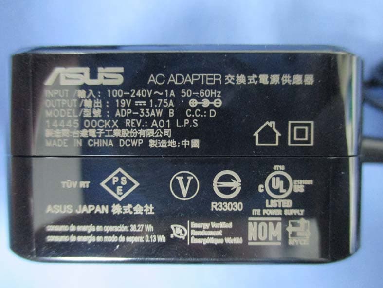
Click to zoom
Application Details
- Equipment Class
- DSS - Part 15 Spread Spectrum Transmitter
- Date of Grant
- May 28, 2015
- Application Purpose
- Original Equipment
- Date of Application
- May 27, 2015
- Equipment Note
- ASUS SRT-AC1900 Wireless Smart Router
- Frequency Range
- 2402.00000000 - 2480.00000000
- Company
- ASUSTeK Computer Inc
- Country
- Taiwan
Documents & Files
Document Text
Text extracted from the exhibit documents filed with the FCC. Open a document above to read the original.
Users Manual
Page 1 ASUS SRT-AC1900 Wireless Smart Router Quick Start Guide Page 2 Package Contents SRT-AC1900 AC adapter Network cable (RJ-45) x 2 Quick Start Guide Support CD (User manual) Cable management clip A Quick look at your SRT-AC1900 LED indicator LAN Firmware restoration WAN USB 3.0 port Power (DC-IN) port Page 3 Installing your router 1. Prepare your modem a、 Unplug the AC adapter from the power outlet and disconnect it from your cable / ADSL modem b、 Disconnect the network cable from your cable/ADSL modem c、 Reboot your computer (recommend). Page 4 2. Set up your wireless environment 1. Insert your wireless router’s AC adapter to the DC-IN port and plug it to a power outlet 2. Using another network cable, connect your modem to your wireless router’s WAN port. 3. Insert your modem’s AC adapter to the DC-IN port and plug it to a power outlet. 4. Using the bundled network cable, connect your computer to your wireless router’s LAN port. 3. Disable some settings on your computer a、 Disable the proxy server, if enabled. b、 Set the TCP/IP settings to automatically obtain an IP address. c、 Disable the dial-up connection, if enabled. Page 5 Setting up your router using the Quick Internet Setup Wizard To set up your router using QIS ((Quick Internet Setup): 1. Plug in the adapter at the back of your router. Ensure that the LED in the front is on. 2. Launch your web browser such as Internet Explorer, Firefox, Google Chrome, or Safari. 3. Assign your router login name and password and click Next. You will need this login name and password to log into SRT-AC1900 to view or change the router settings. You can take note of your router login name and password for future use. 4. The wireless router’s Quick Internet Setup (QIS) feature automatically detects if your ISP connection type is Dynamic IP, PPPoE, PPTP, L2TP, and Static IP. Please obtain the necessary information about your Internet connection type from your Internet Service Provider (ISP). If your connection type is Dynamic IP (DHCP), QIS wizard will automatically direct you to Page 6 the next step. 5. Assign the network name (SSID) and security key for your wireless connection. Click Apply when done. 6. Your Internet and wireless settings are displayed. Click Next to continue. 7. Read the wireless network connection tutorial. When done, click Finish. Page 7 Connect to the wireless network To connect to the wireless network manually from your wireless clients (notebook, tablet PC, smart phone and so on): 1. Enable the Wi-Fi function on your wireless client to scan for available wireless networks. 2. Select the SSID or network name that you assigned to your SRT-AC1900 network. 3. Enter the password and click Connect. Managing the router via the ASUSWRT web GUI Your wireless router comes with the intuitive ASUSWRT web graphical user interface. ASUSWRT allows you to easily configure its various features through a web browser such as Internet Explorer, Firefox, Safari or Google Chrome. Page 8 Frequently Asked Questions (FAQs) 1. After following the steps, I still cannot access the wireless router’s web graphics user interface (web GUI) to configure the wireless router settings. Ensure that your PC's proxy settings are disabled and your PC'S IP address is obtained from the DHCP server automatically. For details on disabling the proxy settings, visit the ASUS Support site at http://support.asus.com. For details on using the DHCP server to obtain IP addresses automatically, refer to your Windows® or Mac operating system’s help feature. 2. The client cannot establish a wireless connection with the router. Out of Range: • Put the router closer to the wireless client. • Try to change the channel settings. Authentication: • Use wired connection to connect to the router. • Check the wireless security settings. • Press the Reset button at the rear panel for more than five seconds. Cannot find the router: • Press the Reset button at the rear panel for more than five seconds. • Check the setting in the wireless adapter such as SSID and encryption settings. Page 9 3. Cannot access the Internet via wireless LAN adapter. • Move the router closer to the wireless client. • Check whether the wireless adapter is connected to the correct wireless router. • Check whether the wireless channel in use conforms to the channels available in your country/area. • Check the encryption settings. • Check if the ADSL or Cable connection is correct. • Retry using another Ethernet cable. 4. If the ADSL “LINK” light blinks continuously or stays off, Internet access is not possible - the Router is unable to establish a connection with the ADSL network. • Ensure that all your cables are all properly connected . • Disconnect the power cord from the ADSL or cable modem, wait a few minutes, then reconnect the cord. • If the ADSL light continues to blink or stays OFF, contact your ADSL service provider. 5. Network name or encryption keys are forgotten. • Try setting up the wired connection and configuring the wireless encryption again. • Press the Reset button of the wireless router for more than five seconds. • Factory default settings: Page 10 6. Where can I find more information about the wireless router? • User Manual in the support CD • Online FAQ site: http://support.asus.com/faq • Technical Support site: http://support.asus.com • Customer Hotline: Refer to the Support Hotline in this Quick Start Guide Page 11 ASUS Recycling/Takeback Services ASUS recycling and takeback programs come from our commitment to the highest standards for protecting our environment. We believe in providing solutions for you to be able to responsibly recycle our products, batteries, other components, as well as the packaging materials. Please go to http://csr.asus.com/english/Takeback.htm for the detailed recycling information in different regions. REACH Complying with the REACH (Registration, Evaluation, Authorisation, and Restriction of Chemicals) regulatory framework, we publishe…
Text truncated - open the document above for the full version.
External Photos
Report No:1550110R-RFUSP28V00 Page: 516 of 541 Attachement EUT Photograph (1) EUT Photo (Power Adatper: PIE, AD891M21) (2) EUT Photo Report No:1550110R-RFUSP28V00 Page: 517 of 541 (3) EUT Photo Report No:1550110R-RFUSP28V00 Page: 518 of 541 (4) EUT Photo (Power Adatper: I.T.E., AD890326) (5) EUT Photo Report No:1550110R-RFUSP28V00 Page: 519 of 541 (6) EUT Photo Report No:1550110R-RFUSP28V00 Page: 520 of 541 (7) EUT Photo (Power Adatper: Delta, ADP-33AW) (8) EUT Photo Report No:1550110R-RFUSP28V00 Page: 521 of 541 (9) EUT Photo
ID Label/Location Info
FCC ID.: MSQ-SRTAC1900 FCC ID AND DoC Label The FCC ID and DoC Label will be placed on the equipment as shown in the photograph below. ASUS SRT-AC1900 Wireless Smart Router Model No.: SRT-AC1900 FCC ID : MSQ-SRTAC1900 This device complies with Part 15 of the FCC Rules. Operation is subject to the following two conditions: (1) this device may not cause harmful interference and (2) this device must accept any interference received, including interference that may cause undesired operation. S/N: Made in Taiwan Trade name: ASUS Model number.: SRT-AC1900
Internal Photos
Report No:1550110R-RFUSP28V00 Page: 522 of 541 (10) EUT Photo (11) EUT Photo Report No:1550110R-RFUSP28V00 Page: 523 of 541 (12) EUT Photo (13) EUT Photo Report No:1550110R-RFUSP28V00 Page: 524 of 541 (14) EUT Photo (15) EUT Photo Report No:1550110R-RFUSP28V00 Page: 525 of 541 (16) EUT Photo (17) EUT Photo Report No:1550110R-RFUSP28V00 Page: 526 of 541 (18) EUT Photo (19) EUT Photo Report No:1550110R-RFUSP28V00 Page: 527 of 541 (20) EUT Photo (21) EUT Photo Report No:1550110R-RFUSP28V00 Page: 528 of 541 (22) EUT Photo (23) EUT Photo Report No:1550110R-RFUSP28V00 Page: 529 of 541 (24) EUT Photo (25) EUT Photo Report No:1550110R-RFUSP28V00 Page: 530 of 541 (26) EUT Photo (27) EUT Photo Report No:1550110R-RFUSP28V00 Page: 531 of 541 (28) EUT Photo (29) EUT Photo Report No:1550110R-RFUSP28V00 Page: 532 of 541 (30) EUT Photo (31) EUT Photo Report No:1550110R-RFUSP28V00 Page: 533 of 541 (32) EUT Photo (33) EUT Photo Report No:1550110R-RFUSP28V00 Page: 534 of 541 (34) EUT Photo (35) EUT Photo Report No:1550110R-RFUSP28V00 Page: 535 of 541 (36) EUT Photo (37) EUT Photo Report No:1550110R-RFUSP28V00 Page: 536 of 541 (38) EUT Photo (39) EUT Photo Report No:1550110R-RFUSP28V00 Page: 537 of 541 (40) EUT Photo Report No:1550110R-RFUSP28V00 Page: 538 of 541 (41) EUT Photo (Antenna) (42) EUT Photo (Antenna) Report No:1550110R-RFUSP28V00 Page: 539 of 541 (43) EUT Photo (Antenna) (44) EUT Photo (Antenna) Report No:1550110R-RFUSP28V00 Page: 540 of 541 (45) EUT Photo (Antenna) (46) EUT Photo (Antenna) Report No:1550110R-RFUSP28V00 Page: 541 of 541 (47) EUT Photo (BT & Zigbee) (48) EUT Photo (Antenna AUX)
RF Exposure Info
Report No. 1550110R-RF-US-Exp-A Page: 1 of 4 RF Exposure Evaluation Declaration Product Name : ASUS SRT-AC1900 Wireless Smart Router Model No. : SRT-AC1900 FCC ID. : MSQ-SRTAC1900 Applicant : ASUSTeK COMPUTER INC. Address : 4F, No. 150, Li-Te Rd., Peitou, Taipei, Taiwan Date of Receipt : 2015/05/04 Date of Declaration : 2015/05/20 Report No. : 1550110R-RF-US-Exp-A Report Version : V1.0 The declaration results relate only to the samples calculated. The declaration shall not be reproduced except in full without the written approval of QuieTek Corporation. Report No. 1550110R-RF-US-Exp-A Page: 2 of 4 1. RF Exposure Evaluation 1.1. Limits According to FCC 1.1310: The criteria listed in the following table shall be used to evaluate the environment impact of human exposure to radio frequency (RF) radiation as specified in 1.1307(b) LIMITS FOR MAXIMUM PERMISSIBLE EXPOSURE (MPE) Frequency Range (MHz) Electric Field Strength (V/m) Magnetic Field Strength (A/m) Power Density (mW/cm 2 ) Average Time (Minutes) (A) Limits for Occupational/ Control Exposures 300-1500 -- -- F/300 6 1500-100,000 -- -- 5 6 (B) Limits for General Population/ Uncontrolled Exposures 300-1500 -- -- F/1500 6 1500-100,000 -- -- 1 30 F= Frequency in MHz Friis Formula Friis transmission formula: Pd = (Pout*G)/(4*pi*r 2 ) Where Pd = power density in mW/cm 2 Pout = output power to antenna in mW G = gain of antenna in linear scale Pi = 3.1416 R = distance between observation point and center of the radiator in cm Pd id the limit of MPE, 1 mW/cm 2 . If we know the maximum gain of the antenna and the total power input to the antenna, through the calculation, we will know the distance r where the MPE limit is reached. 1.2. Test Procedure Software provided by client enabled the EUT to transmit and receive data at lowest, middle and highest channel individually. The temperature and related humidity: 18°Cand 78% RH. Report No. 1550110R-RF-US-Exp-A Page: 3 of 4 1.3. Test Result of RF Exposure Evaluation Product ASUS SRT-AC1900 Wireless Smart Router Test Mode Transmit Test Condition RF Exposure Evaluation Antenna Gain Antenna Gain: The maximum Gain measured in fully anechoic chamber is 3.61dBi or 2.3 in linear scale. Output Power into Antenna & RF Exposure Evaluation Distance: GFSK Bluetooth Function Channel Channel Frequency (MHz) Output Power to Antenna (mW) Power Density at R = 20 cm (mW/cm 2 ) 00 2402 11.6413 0.00533 39 2441 14.8252 0.00678 78 2480 16.3456 0.00748 π/4 DQPSK Bluetooth Function Channel Channel Frequency (MHz) Output Power to Antenna (mW) Power Density at R = 20 cm (mW/cm 2 ) 00 2402 10.5536 0.00483 39 2441 13.2923 0.00608 78 2480 14.5479 0.00666 The power density Pd (4th column) at a distance of 20 cm calculated from the Friis transmission formula is far below the limit of 1 mW/cm 2 . Report No. 1550110R-RF-US-Exp-A Page: 4 of 4 Product ASUS SRT-AC1900 Wireless Smart Router Test Mode Transmit Test Condition RF Exposure Evaluation Antenna Gain Antenna Gain: The maximum Gain measured in fully anechoic chamber is 3.61dBi or 2.3 in linear scale. Output Power into Antenna & RF Exposure Evaluation Distance: 8DQPSK Bluetooth Function Channel Channel Frequency (MHz) Output Power to Antenna (mW) Power Density at R = 20 cm (mW/cm 2 ) 00 2402 6.6865 0.00306 39 2441 8.7237 0.00399 78 2480 9.5345 0.00436 The power density Pd (4th column) at a distance of 20 cm calculated from the Friis transmission formula is far below the limit of 1 mW/cm 2 .
Test Setup Photos
Report No:1550110R-RFUSP28V00 Page: 26 of 541 2.8. Test Photo Test Mode : Mode 1: Tx- Horizontal Antenna (AD891M21) Description: Front View of Conducted Emission Test Setup Test Mode : Mode 1: Tx- Horizontal Antenna (AD891M21) Description: Back View of Conducted Emission Test Setup Report No:1550110R-RFUSP28V00 Page: 27 of 541 Test Mode : Mode 3: Tx- Horizontal Antenna (AD890326) Description: Front View of Conducted Emission Test Setup Test Mode : Mode 3: Tx- Horizontal Antenna (AD890326) Description: Back View of Conducted Emission Test Setup Report No:1550110R-RFUSP28V00 Page: 28 of 541 Test Mode : Mode 5: Tx- Horizontal Antenna (ADP-33AW) Description: Front View of Conducted Emission Test Setup Test Mode : Mode 5: Tx- Horizontal Antenna (ADP-33AW) Description: Back View of Conducted Emission Test Setup Report No:1550110R-RFUSP28V00 Page: 229 of 541 4.8. Test Photo Test Mode : Mode 1: Tx- Horizontal Antenna (AD891M21) Description: Front View of Radiated Emission Test Setup (Bi-Log) Test Mode : Mode 1: Tx- Horizontal Antenna (AD891M21) Description: Back View of Radiated Emission Test Setup (Bi-Log) Report No:1550110R-RFUSP28V00 Page: 230 of 541 Test Mode : Mode 2: Tx- Vertical Antenna (AD891M21) Description: Front View of Radiated Emission Test Setup (Bi-Log) Test Mode : Mode 2: Tx- Vertical Antenna (AD891M21) Description: Back View of Radiated Emission Test Setup (Bi-Log) Report No:1550110R-RFUSP28V00 Page: 231 of 541 Test Mode : Mode 3: Tx- Horizontal Antenna (AD890326) Description: Front View of Radiated Emission Test Setup (Bi-Log) Test Mode : Mode 3: Tx- Horizontal Antenna (AD890326) Description: Back View of Radiated Emission Test Setup (Bi-Log) Report No:1550110R-RFUSP28V00 Page: 232 of 541 Test Mode : Mode 4: Tx- Vertical Antenna (AD890326) Description: Front View of Radiated Emission Test Setup (Bi-Log) Test Mode : Mode 4: Tx- Vertical Antenna (AD890326) Description: Back View of Radiated Emission Test Setup (Bi-Log) Report No:1550110R-RFUSP28V00 Page: 233 of 541 Test Mode : Mode 5: Tx- Horizontal Antenna (ADP-33AW) Description: Front View of Radiated Emission Test Setup (Bi-Log) Test Mode : Mode 5: Tx- Horizontal Antenna (ADP-33AW) Description: Back View of Radiated Emission Test Setup (Bi-Log) Report No:1550110R-RFUSP28V00 Page: 234 of 541 Test Mode : Mode 6: Tx- Vertical Antenna (ADP-33AW) Description: Front View of Radiated Emission Test Setup (Bi-Log) Test Mode : Mode 6: Tx- Vertical Antenna (ADP-33AW) Description: Back View of Radiated Emission Test Setup (Bi-Log) Report No:1550110R-RFUSP28V00 Page: 235 of 541 Test Mode : Mode 1: Tx- Horizontal Antenna (AD891M21) Description: Front View of Radiated Emission Test Setup (Horn) Test Mode : Mode 1: Tx- Horizontal Antenna (AD891M21) Description: Back View of Radiated Emission Test Setup (Horn) Report No:1550110R-RFUSP28V00 Page: 236 of 541 Test Mode : Mode 2: Tx- Vertical Antenna (AD891M21) Description: Front View of Radiated Emission Test Setup (Horn) Test Mode : Mode 2: Tx- Vertical Antenna (AD891M21) Description: Back View of Radiated Emission Test Setup (Horn)
Contact Information
Applicant
Jackson Yen(Associate Vice President)
Technical Contact
QuieTek CorporationNeil Yeh
[email protected]886-3-592-8858
N0. 75-2, 3rd Lin, Wangye Keng,Yonghxing Tsuen, · Taiwan
Non-Technical Contact
QuieTek CorporationSabrina Tsai
[email protected]886-3-592-8858
Test Firm
QuieTek CorporationWarren Lin
Technical Specifications
| # | Rule Parts | Frequency Range | Power Output |
|---|---|---|---|
| 1 | 15C | 2.40 GHz - 2.48 GHz | 16.00 mW |
Other Applications from ASUSTeK Computer Inc

MSQ-GC701
Aug 21, 2026Wireless Gaming Controller
Equipment Class
DSS - Part 15 Spread Spectrum TransmitterMSQMPDONGLE3
Aug 18, 2026WIRELESS DONGLE
Equipment Class
DTS - Digital Transmission System
MSQ-GC701D
Aug 13, 2026USB Wireless Dongle
Equipment Class
DSS - Part 15 Spread Spectrum TransmitterMSQ-CM3206DM4A
May 27, 2026Chromebook/Notebook PC
Equipment Class
DCD - Part 15 Low Power Transmitter Below 1705 kHz
MSQ-GST868003
Apr 03, 2026MODULE-WIRELESS CHRG
Equipment Class
DCD - Part 15 Low Power Transmitter Below 1705 kHz