MSQAAM6KTPB2Wireless ADSL Router
ASUSTeK Computer Inc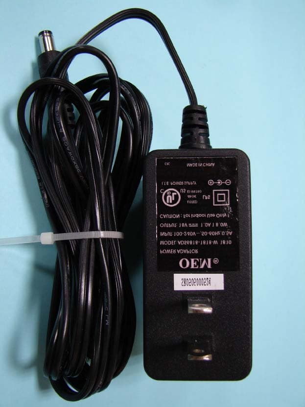
Click to zoom
Application Details
- Equipment Class
- DTS - Digital Transmission System
- Date of Grant
- Nov 24, 2005
- Application Purpose
- Original Equipment
- Date of Application
- Nov 24, 2005
- Equipment Note
- Wireless ADSL Router
- Frequency Range
- 2412.00000000 - 2462.00000000
- Company
- ASUSTeK Computer Inc
- Country
- Taiwan
Documents & Files
Document Text
Text extracted from the exhibit documents filed with the FCC. Open a document above to read the original.
Users Manual
TriplePlay User Manual Version 1.0 Version Date: August 1, 2005 Document #: BD-TU0001-10 TriplePlay User Manual 1 Version 1.0 Document #: BD-TU0001-10 Table of Contents GENERALINFORMATION...............................................................3 Package Contents ..................................................................3 Safety Instructions—Please read. ...........................................3 Front Panel View ....................................................................4 Indication................................................................................4 Back Panel View ....................................................................6 I NSTALLING THEROUTER..............................................................7 Connect the ADSL Line and Telephone.................................7 Connect the PC to the Router ................................................7 Connect a Printer or Server to the Router ..............................8 Connect the Telephone to the Router ....................................8 Connect the Router to a Phone Jack .....................................8 Connect the Power Adapter ...................................................8 I NSTALLATIONDIAGRAM...............................................................9 USB D RIVERINSTALLATION.......................................................10 C ONFIGURINGYOURCOMPUTER................................................14 Windows 2000......................................................................14 Windows XP ......................................................................... 15 L OG IN TO THEROUTER..............................................................16 D EVICEINFO..............................................................................17 Summary ..............................................................................17 WAN .....................................................................................17 Statistics...............................................................................18 LAN Statistics................................................................18 WAN Statistics ..............................................................18 ATM Statistics ...............................................................19 ADSL Statistics .............................................................19 ADSL BER Test ............................................................ 20 Route....................................................................................21 ARP ......................................................................................21 DHCP ...................................................................................22 Q UICKSETUP............................................................................22 A DVANCEDSETUP.....................................................................26 WAN .....................................................................................26 LAN Local Area Network (LAN) Setup .................................31 NAT ......................................................................................32 Virtual Servers ..............................................................32 Port Triggering ..............................................................34 DMZ Host ......................................................................35 Firewall .................................................................................36 IP Filtering—Outgoing ....................................................36 IP Filtering—Incoming ....................................................37 TriplePlay User Manual 2 Version 1.0 Document #: BD-TU0001-10 MAC Filtering ................................................................38 Parental Control ............................................................39 Quality of Service .................................................................40 Routing .................................................................................43 Default Gateway ...........................................................43 Static Route ..................................................................43 RIP ................................................................................44 DNS......................................................................................44 DNS Server ...................................................................44 Dynamic DNS ...............................................................45 ADSL ....................................................................................46 DSL Advanced Settings ................................................47 Tone Settings ................................................................47 Port Mapping ........................................................................ 48 W IRELESS.................................................................................49 Basic ....................................................................................49 Security ................................................................................49 MAC Filter ............................................................................51 Wireless Bridge ....................................................................52 Advanced .............................................................................52 Station Info ........................................................................... 54 V OICE.......................................................................................55 SIP Basic.............................................................................. 55 SIP Advanced ......................................................................58 Phonebook ...........................................................................61 Call History ...........................................................................62…
Text truncated - open the document above for the full version.
Users Manual
TriplePlay User Manual 49 Version 1.0 Document #: BD-TU0001-10 Wireless This section allows you to configure wireless settings on your router. Basic The below Wireless – Basic screen lets you enable or disable wireless. The default setting for wireless is enabled. You can also hide the access point so others cannot see your ID on the network. Security The next screen is the Wireless – Security screen which allows you to select the network authentication method and to enable or disable WEP encryption. Note that depending on the network authentication that is selected, the screen will change accordingly so additional fields can be configured for the specific authentication method. TriplePlay User Manual 50 Version 1.0 Document #: BD-TU0001-10 Network authentication methods include the following— •Open—anyone can access the network. The default is a disabled WEP encryption setting. •Shared—WEP encryption is enabled and encryption key strength of 64-bit or 128-bit needs to be selected. Click on Set Encryption Keys to manually set the network encryption keys. Up to 4 different keys can be set and you can come back to select which one to use at anytime. •802.1X—requires mutual authentication between a client station and the router by including a RADIUS-based authentication server. Information about the RADIUS server such as its IP address, port and key must be entered. WEP encryption is also enabled and the encryption strength must also be selected. •WPA—(Wi-Fi Protected Access)— usually used for the larger Enterprise environment, it uses a RADIUS server and TKIP (Temporal Key Integrity Protocol) encryption (instead of WEP encryption which is disabled). TKIP uses128-bit dynamic session keys (per user, per session, and per packet keys). •WPA-PSK (Wi-Fi Protected Access – Pre-Shared Key)— WPA for home and SOHO environments also using the same strong TKIP encryption, per-packet key construction, and key management that WPA provides in the enterprise environment. The main difference is that the password is entered manually. A group re-key interval time is also required. •WPA2 (Wi-Fi Protected Access 2)—second generation of WPA which uses AES (Advanced Encryption Standard) instead of TKIP as its encryption method. Network re-auth interval is the time in which another key needs to be dynamically issued. •WPA2-PSK (Wi-Fi Protected Access 2 – Pre-Shared Key)— suitable for home and SOHO environments, it also uses AES encryption and requires you to enter a password and an re-key interval time. •Mixed WPA2 / WPA—during transitional times for upgrades in the enterprise environment, this mixed authentication method allows “upgraded” and users not yet “upgraded” to TriplePlay User Manual 51 Version 1.0 Document #: BD-TU0001-10 access the network via the router. RADIUS server information must be entered for WPA and a as well as a group re-key interval time. Both TKIP and AES are used. •Mixed WPA2 / WPA-PSK—useful during transitional times for upgrades in the home or SOHO environment, a pre- shared key must be entered along with the group re-key interval time. Both TKIP and AES are also used. MAC Filter The MAC filter screen allows you to manage MAC address filters. Add the MAC addresses that you want to manage and then select the mode that you want to use to manage them. You can disable this feature or you can allow or deny access to the MAC addresses that you add to the list. The following screen allows you to add a MAC address to the filter. When completed, click on the Save / Apply button. TriplePlay User Manual 52 Version 1.0 Document #: BD-TU0001-10 Wireless Bridge In this next screen you can select the mode, either access point or wireless bridge that you want the router to be in. In the screen below, bridge restrict is enabled, therefore you see the remote bridges MAC address fields. If bridge restrict is disabled, then there is nothing left to do afterwards. Click on Save / Apply to continue. Advanced Advanced features of the wireless LAN interface can be configured in this section. Settings can be configured for the following— •AP Isolation—if you select enable, then each of your wireless clients will not be able to communicate with each other. •Band—a default setting at 2.4GHz – 802.11g •Channel— 802.11b and 802.11g use channels to limit interference from other devices. If you are experiencing interference with another 2.4Ghz device such as a baby monitor, security alarm, or cordless phone, then change the channel on your router. •Multicast Rate—the rate at which a message is sent to a specified group of recipients. TriplePlay User Manual 53 Version 1.0 Document #: BD-TU0001-10 •Basic Rate—the set of data transfer rates that all the stations will be capable of using to receive frames from a wireless medium. •Fragmentation Threshold—used to fragment packets which help improve performance in the presence of radio frequency (RF) interference. •RTS Threshold (Request to Send Threshold)—determines the packet size of a transmission through the use of the router to help control traffic flow. •DTIM Interval—sets the Wake-up interval for clients in power-saving mode. •Beacon Interval—a packet of information that is sent from a connected device to all other devices where it announces its availability and readiness. A beacon interval is a period of time (sent with the beacon) before sending the beacon again. The beacon interval may be adjusted in milliseconds (ms). •Xpress Technology—a technology that utilizes standards based on framebursting to achieve higher throughput. With Xpress Technology enabled, aggregate throughput (the sum of the individual throughput speeds of each client on the network) can improve by up to 25% in 802.11g only networks and up to 75% in mixed networks comprised of 802.11g and 802.11b equipment. •54g Mode— 54g is a Broadcom Wi-Fi technology. •54g Protection--the 802.11g standards provide a protection method so 802.11g and 802.11b devices can co-exist in the same network without “spe…
Text truncated - open the document above for the full version.
Cover Letter(s)
ASUSTeK COMPUTER INC. Tel : +886-2-28943447 Fax : +886-2-28950114 www.asus.com Request for Confidentiality Federal Communications Commission Authorization and Evaluation Division Subject: : Confidentiality Request regarding application for certification of FCC ID: MSQAAM6KTPB2 Dear Madam or Sir: Pursuant to Sections 0.457 and 0.459 of the Commission’s Rules, we hereby request confidential treatment of information accompanying this application as outlined below: z Schematics z Part List z Block diagram z Operational description The above materials contain trade secrets and proprietary information not customarily released to the public. The public disclosure of these materials may be harmful to the applicant and provide unjustified benefits to its competitors. The applicant understands that pursuant to Section 0.457 of the Rules, disclosure of this application and all accompanying documentation will not be made before the date of the Grant for this application. Pursuant to DA 04-1705 June 15, 2004 of the Commission’s public notice, we also request temporary confidential treatment of information accompanying this application as outlined below: z External Photos z Internal Photos z Test Setup Photos z User’s Manual Sincerely, Lawrence Yu / Manager, ASUSTek Computer Inc.
External Photos
External Photos of Wireless Router --------------------------------------------------1/15 Applicant: ASUSTeK Computer Inc.FCC ID: MSQAAM6KTPB2 Training Research Co., Ltd., TEL: 886-2-26935155, Fax: 886-2-26934440 Antenna#1 Model: GY111C163-010 Antenna Gain: 3.13dBi External Photos of Wireless Router --------------------------------------------------2/15 Applicant: ASUSTeK Computer Inc.FCC ID: MSQAAM6KTPB2 Training Research Co., Ltd., TEL: 886-2-26935155, Fax: 886-2-26934440 External Photos of Wireless Router --------------------------------------------------3/15 Applicant: ASUSTeK Computer Inc.FCC ID: MSQAAM6KTPB2 Training Research Co., Ltd., TEL: 886-2-26935155, Fax: 886-2-26934440 Antenna#2 Model: C660-510059-A Antenna Gain: 1.80dBi External Photos of Wireless Router --------------------------------------------------4/15 Applicant: ASUSTeK Computer Inc.FCC ID: MSQAAM6KTPB2 Training Research Co., Ltd., TEL: 886-2-26935155, Fax: 886-2-26934440 External Photos of Wireless Router --------------------------------------------------5/15 Applicant: ASUSTeK Computer Inc.FCC ID: MSQAAM6KTPB2 Training Research Co., Ltd., TEL: 886-2-26935155, Fax: 886-2-26934440 Antenna#1 Model: GY111C163-010 Gain: 3.13dBi External Photos of Wireless Router --------------------------------------------------6/15 Applicant: ASUSTeK Computer Inc.FCC ID: MSQAAM6KTPB2 Training Research Co., Ltd., TEL: 886-2-26935155, Fax: 886-2-26934440 External Photos of Wireless Router --------------------------------------------------7/15 Applicant: ASUSTeK Computer Inc.FCC ID: MSQAAM6KTPB2 Training Research Co., Ltd., TEL: 886-2-26935155, Fax: 886-2-26934440 Antenna#2 Model: C660-510059-A Gain: 1.80dBi External Photos of Wireless Router --------------------------------------------------8/15 Applicant: ASUSTeK Computer Inc.FCC ID: MSQAAM6KTPB2 Training Research Co., Ltd., TEL: 886-2-26935155, Fax: 886-2-26934440 Power Adapter ofWireless Router----------------------------------------------------9/15 Applicant: ASUSTeK Computer Inc.FCC ID: MSQAAM6KTPB2 Training Research Co., Ltd., TEL: 886-2-26935155, Fax: 886-2-26934440 Adapter#1 Model: DVS-180A10FUS Power Adapter ofWireless Router----------------------------------------------------10/15 Applicant: ASUSTeK Computer Inc.FCC ID: MSQAAM6KTPB2 Training Research Co., Ltd., TEL: 886-2-26935155, Fax: 886-2-26934440 Adapter#2 Model: ADS6818-1818-W 1810
ID Label/Location Info
LABEL Sample and Location information ------------------------------------------------- 1/3 Applicant: ASUSTeK Computer Inc. FCC ID: MSQAAM6KTPB2 Training Research Co., Ltd., TEL: 886-2-26935155, Fax: 886-2-26934440 LABEL Format: LABEL Sample and Location information ------------------------------------------------- 2/3 Applicant: ASUSTeK Computer Inc. FCC ID: MSQAAM6KTPB2 Training Research Co., Ltd., TEL: 886-2-26935155, Fax: 886-2-26934440 LABEL Position: LABEL Size: 82 x 42 mm LABEL Sample and Location information ------------------------------------------------- 3/3 Applicant: ASUSTeK Computer Inc. FCC ID: MSQAAM6KTPB2 Training Research Co., Ltd., TEL: 886-2-26935155, Fax: 886-2-26934440 LABEL Position: LABEL Size: 60 x 30 mm LABEL
Internal Photos
Internal Photos ofWireless Router---------------------------------------------------11/15 Applicant: ASUSTeK Computer Inc.FCC ID: MSQAAM6KTPB2 Training Research Co., Ltd., TEL: 886-2-26935155, Fax: 886-2-26934440 Internal Photos ofWireless Router---------------------------------------------------12/15 Applicant: ASUSTeK Computer Inc.FCC ID: MSQAAM6KTPB2 Training Research Co., Ltd., TEL: 886-2-26935155, Fax: 886-2-26934440 Internal Photos ofWireless Router---------------------------------------------------13/15 Applicant: ASUSTeK Computer Inc.FCC ID: MSQAAM6KTPB2 Training Research Co., Ltd., TEL: 886-2-26935155, Fax: 886-2-26934440 Internal Photos ofWireless Router---------------------------------------------------14/15 Applicant: ASUSTeK Computer Inc.FCC ID: MSQAAM6KTPB2 Training Research Co., Ltd., TEL: 886-2-26935155, Fax: 886-2-26934440 Internal Photos ofWireless Router---------------------------------------------------15/15 Applicant: ASUSTeK Computer Inc.FCC ID: MSQAAM6KTPB2 Training Research Co., Ltd., TEL: 886-2-26935155, Fax: 886-2-26934440
RF Exposure Info
Measurement of Maximum Permissible Exposure ---------------------------------------- 1/3 Applicant: ASUSTeK Computer Inc. FCC ID: MSQAAM6KTPB2 Training Research Co., Ltd., TEL: 886-2-26935155, Fax: 886-2-26934440 Measurement of Maximum Permissible Exposure 1. Foreword In adopt with the Human Exposure IEEE C95.1, and according to the FCC 1.1310. The Maximum Permissible Exposure (MPE) is obligated to measure in order to prove the safety of radiation harmfulness to the human body. The Gain of the antenna used is measured in an Anechoic chamber. The maximum total power to the antenna is to be recorded. By adopting the Friis Transmission Formula and the power gain of the antenna, we can find the distance right away from the product, where the limit of the MPE is. 2. Description of EUT FCC ID : MSQAAM6KTPB2 Product Name : Wireless ADSL Router Model Name : AAM6XXXTPB2; 6238-I2-XXX; AM200g Frequency Range : 2.412GHz ~ 2.462GHz Channel Spacing : 5MHz Support Channel : 11 Channels Modulation Skill : DBPSK, DQPSK, CCK, OFDM Power Type : Powered by the switching adapter (1) or (2), 1) Model: DVS-180A10FUS [DVE] I/P: 100-240VAC 50/60Hz 0.7A O/P: 18VDC 1A 190cm length, non-shielded, with ferrite core 2) Model: ADS6818-1818-W 1810 [OEM] I/P: 100-240VAC 50-60Hz 0.5A O/P: 18VDC 1A 18W 190cm length, non-shielded, no ferrite core Measurement of Maximum Permissible Exposure ---------------------------------------- 2/3 Applicant: ASUSTeK Computer Inc. FCC ID: MSQAAM6KTPB2 Training Research Co., Ltd., TEL: 886-2-26935155, Fax: 886-2-26934440 3. Limits for Maximum Permissible Exposure (MPE) Frequency Range (MHz) Electric Field Strength (V/m) Magnetic Filed Strength (H) (A/m) Power Density (S) (mW/cm2) Averaging Time |E| 2 , |H| 2 or S (minutes) (A) Limits for Occupational/Controlled Exposure 0.3-3.0 614 1.63 100 6 3.0-30 1842/f 4.89/f 900/f 2 6 30-300 61.4 0.163 1.0 6 300-1500 -- -- f/300 6 1500-100,000 -- -- 5 6 (B) Limits for General Population/Uncontrolled Exposure 0.3-1.34 614 1.63 100 30 1.34-30 824/f 2.19/f 180/f 2 30 30-300 27.5 0.073 0.2 30 300-1500 -- -- f/1500 30 1500-100,000 -- -- 1.0 30 [The EUT is tested in transmit and receive modes and in the first, middle and the last channel separately. The following shows only our observation have the greatest emissions.] According to OET BULLETIN 56 Fourth Edition/August 1999, Equation for Predicting RF Fields: Friis Transmission Formula: 2 22 /03970.0 )20(4 056.2051.97 4 cmmW R PG S= × == ππ Estimated safe separation: cm PG R98480.3 4 056.2051.97 4 = × == ππ Note: "The safe estimated separation that the user must maintain from the antenna is at least 3.98cm" Where: S = power density (in appropriate units, e.g. mW/cm2) P = power input to the antenna (in appropriate units, e.g., mW) G = power gain of the antenna in the direction of interest relative to an isotropic radiator R = distance to the center of radiation of the antenna (appropriate units, e.g., cm) The Numeric gain G of antenna with a gain specified in dB is determined by: G = Log -1 ( dB antenna gain / 10 ) G = Log -1 (3.13 / 10) = 2.05589 Measurement of Maximum Permissible Exposure ---------------------------------------- 3/3 Applicant: ASUSTeK Computer Inc. FCC ID: MSQAAM6KTPB2 Training Research Co., Ltd., TEL: 886-2-26935155, Fax: 886-2-26934440 Appendix Antenna Specification 規格承認書 Specification for Approval 客 戶: 華 碩 Customer 品 名: 2.4GHz SMA Antenna Part name 料 號: GY111C163-010 Part No. 客戶承認印 CUSTOMER APPROVED BY APPROVAL CHIEF SUPERVISOR Approval No. Model Part No. CHIEF SALES R&D DESIGN Leo Gary Hui Kao Date: August.19.2005 Date: August.19.2005 驊 陞 科 技 股 份 有 限 公 司 WIESON TECHNOLOGIES CO., LTD. WIESON TECHNOLOGIES CO., LTD. TEST METHODS OF THE CHAMBER PAGE : 1/4 I. Pattern Measurement: (a) Instruments:anechoic chamber, network analyzer, standard gain antenna. (b) chamber description: (1) The anechoic chamber is a far-field measurement system with size of 3.25M*2.84M*6.4M. The quiet zone region is 44cm*44cm*44cm at frequency range of 2.4GHz in the center of the rotator. Fig.1. The interior components of the anechoic (2) Fig. 1. shows the interior components of the anechoic chamber. The antenna standard antenna as probe and antenna under test is 3M. The antenna under test is fixed on a step rotator. We can control the rotating angle for accurate or rough measurement. (3) While we measure the radiation patterns by rotating AUT with 360 degrees and repeat again by replacing the AUT with the standard gain antenna under test, we compare both data and using a formula to obtain the G AUT = G stand + P AUT - P stand G AUT :Gain of AUT G stand :Gain of Standard Gain Antenna P AUT :Measured Power of AUT WIESON TECHNOLOGIES CO., LTD. TEST METHODS OF THE CHAMBER PAGE : 2/4 P stand :Measured Power of Standard Gain Antenna (4) Gain of AUT. The standard gain antenna is a gain horn( SG-430 1.7GHz ~ 2.6GHz ). (5) The planes defined in the Fig. 4 which we want to measure are H(X-Y) and E(X-Z) planes. The vertical or horizontal polarization’s power is measured by rotating the antenna probe to 0 degree or to 90 degree shown in Fig. 3, respectively. While we combine both vertical and horizontal power, we obtain total power. (6) From the total power in three basic planes( H, and E ), we can analyze the performance of the antenna is good or not. (a) Antenna Probe at 0 degree (b) Antenna Probe at 90 degree as a vertical polarization. as a horizontal polarization. Fig. 3. The definition of vertical and horizontal polarization. (c) Plane definition: Fig. 4. The plane definition:H-Planes and E-Planes. WIESON TECHNOLOGIES CO., LTD. TEST METHODS OF THE CHAMBER PAGE : 3/4 II. Gain and Radiation Pattern: (a) H-PALNE: (1) Gain Frequency(GHz) Gain(dBi) 2.40 2.45 2.5 Peak Gain 1.34762 1.96789 2.12256 Avg Gain 1.115 1.778 1.902 (2) Radiation Pattern 0 345 330 315 300 285 270 255 240 225 210 195 180 165 150 135 120 105 90 75 60 45 30 15 -30-20-100 dB Far-field amplitude of 2.4GHz SMA Antenna H-Plane.nsi 2.400000 GHz2.450000 GHz2.50…
Text truncated - open the document above for the full version.
Test Report
Test Report -------------------------------------------------------------------------------1/77 Report No.: A5415050742, FCC Part 15.247 Training Research Co., Ltd., TEL: 886-2-26935155, Fax: 886-2-26934440 MEASUREMENT REPORT of Wireless ADSL Router Applicant:ASUSTek Computer Inc. EUT : Wireless ADSL Router Model No.:AAM6XXXTPB2 ; 6238-I2-XXX ; AM200g FCC ID:MSQAAM6KTPB2 Tested by : Training Research Co., Ltd. TEL : 886-2-26935155 FAX : 886-2-26934440 No. 255, Nanyang Street, Shijr, Taipei Hsien 221, Taiwan, R.O.C. Test Report -------------------------------------------------------------------------------2/77 Report No.: A5415050742, FCC Part 15.247 Training Research Co., Ltd., TEL: 886-2-26935155, Fax: 886-2-26934440 CERTIFICATION We here by verify that: The test data, data evaluation, test procedures and equipment configurations shown in this report were made mainly in accordance with the procedures given in ANSI C63.4 (2003) as a reference. All test were conducted by Training Research Co., Ltd., 255 Nanyang Street, Shijr, Taipei Hsien 221, Taiwan, R.O.C. Also, we attest to the accuracy of each. We further submit that the energy emitted by the sample EUT tested as described in the report is in compliance with the technical requirements set forth in the FCC Rules Part 15 Subpart B (Declaration of Conformity) and C Section 15.247. Applicant:ASUSTek Computer Inc. Applicant Address:4F, No. 150, Li-Te Rd., Peitou, Taipei, Taiwan, R.O.C. Product Name : Wireless ADSL Router Model:AAM6XXXTPB2 ; 6238-I2-XXX ; AM200g Report No.:A5415050742 Test Date:November23, 2005 Prepared by:Approved by: Jack TsaiFrank Tsai Conditions of issue : (1) This test report shall not be reproduced except in full, without written approval of TRC. And the test result contained within this report only relate to the sample submitted for testing. (2) This report must not be used by the client to claim product endorsement by NVLAP or any agency of U.S. Government. (3) This test report, measurements made by TRC are traceable to the NIST only Conducted and Radiated Method. NVLAP LAB CODE: 200174-0 Test Report -------------------------------------------------------------------------------3/77 Report No.: A5415050742, FCC Part 15.247 Training Research Co., Ltd., TEL: 886-2-26935155, Fax: 886-2-26934440 Federal Communications Commission Declaration of Conformity for the following equipment: Product name : Wireless ADSL Router Trade name:ASUS ; PARADYNE ; ZHONE Model name:AAM6XXXTPB2 ; 6238-I2-XXX ; AM200g Is herewith confirmed and found to comply with the requirements of CFR 47 part15 Subpart B - Unintentional Radiators regulation. The results of electromagnetic mission evaluation are shown in the report number : A5415050742 This device complies with Part 15 of the FCC Rules. Operation is subject to the following two conditions: (1) This device may not cause harmful interference, and (2) This device must accept any interference received, including interference that may cause undesired operation ManufacturerUSA local representative Company name: ASUSTeK Computer Inc.To be determined Computer address: 4/F, 150, Li-Te Rd., Peitou, Taipei, Taiwan ZIP / Postal code 112 Contact person: Lawrence Yu Title: Manager Internet e -mail address: [email protected] Tel / Fax: 886-2-28943447 / 886-2-28950113 Test Report -------------------------------------------------------------------------------4/77 Report No.: A5415050742, FCC Part 15.247 Training Research Co., Ltd., TEL: 886-2-26935155, Fax: 886-2-26934440 Tables of Contents I.GENERAL................................................................................................................... 6 1.1Introduction........................................................................................................... 6 1.2Description of EUT ................................................................................................ 6 1.3Test method .......................................................................................................... 7 1.4Description of Support Equipment .......................................................................... 8 1.5Configuration of System Under Test ...................................................................... 11 1.6Verify the Frequency and Channel ......................................................................... 13 1.7Test Procedure ..................................................................................................... 14 1.8Location of the Test Site ....................................................................................... 14 1.9General Test Condition ......................................................................................... 14 II.Section 15.101(a) : Equipment Authorization of Unintentional Radiators................. 15 III.Section 15.203 : Antenna Requirement....................................................................... 16 IV.Section 15.207 : Power Line Conducted Emissions for AC Powered Units............. 17 4.1Test Condition & Setup ........................................................................................ 17 4.2List of Test Instruments ......................................................................................... 18 4.3Test Result of Conducted Emissions ...................................................................... 19 Adapter#1 DVE [DVS-180A10FUS]....................................................................... 19 Adapter#2 OEM [ADS6818-1818-W 1810].............................................................. 23 V.Section 15.247(a) : Technical Description of the EUT................................................ 27 VI.Section 15.247(a)(2) : Bandwidth for Direct Sequence System................................ 28 6.1Test Condition & Setup ........................................................................................ 28 6.2Test Instruments Configuration .................................................…
Text truncated - open the document above for the full version.
Test Setup Photos
Test Setup Photos ------------------------------------------------------------------------ 1/2 Applicant: ASUSTeK Computer Inc. FCC ID: MSQAAM6KTPB2 Training Research Co., Ltd., TEL: 886-2-26935155, Fax: 886-2-26934440 Conducted Test Setup Placement: Front View of the Test Configuration Side View of the Test Configuration Test Setup Photos ------------------------------------------------------------------------ 2/2 Applicant: ASUSTeK Computer Inc. FCC ID: MSQAAM6KTPB2 Training Research Co., Ltd., TEL: 886-2-26…
Text truncated - open the document above for the full version.
Contact Information
Applicant
Jackson Yen(Associate Vice President)
Test Firm
Training Research Co., Ltd.Jack Tsai
Technical Specifications
| # | Rule Parts | Frequency Range | Power Output |
|---|---|---|---|
| 1 | 15C | 2.41 GHz - 2.46 GHz | 97.00 mW |
Other Applications from ASUSTeK Computer Inc

MSQ-GC701
Aug 21, 2026Wireless Gaming Controller
Equipment Class
DSS - Part 15 Spread Spectrum TransmitterMSQMPDONGLE3
Aug 18, 2026WIRELESS DONGLE
Equipment Class
DTS - Digital Transmission System
MSQ-GC701D
Aug 13, 2026USB Wireless Dongle
Equipment Class
DSS - Part 15 Spread Spectrum TransmitterMSQ-CM3206DM4A
May 27, 2026Chromebook/Notebook PC
Equipment Class
DCD - Part 15 Low Power Transmitter Below 1705 kHz
MSQ-GST868003
Apr 03, 2026MODULE-WIRELESS CHRG
Equipment Class
DCD - Part 15 Low Power Transmitter Below 1705 kHz