MSQAAM6KVIT4ADSL WIRELESS MODEM ROUTER
ASUSTeK Computer Inc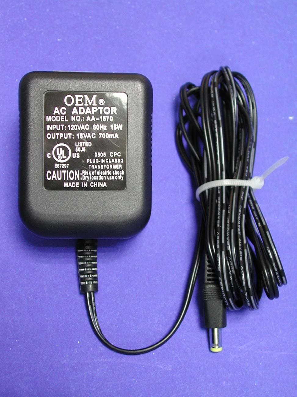
Click to zoom
Application Details
- Equipment Class
- DTS - Digital Transmission System
- Date of Grant
- Nov 02, 2005
- Application Purpose
- Original Equipment
- Date of Application
- Nov 02, 2005
- Equipment Note
- ADSL WIRELESS MODEM ROUTER
- Frequency Range
- 2412.00000000 - 2462.00000000
- Company
- ASUSTeK Computer Inc
- Country
- Taiwan
Documents & Files
Document Text
Text extracted from the exhibit documents filed with the FCC. Open a document above to read the original.
Users Manual
AAM6020VI ADSL Wireless Modem Router Quick Installation Guide Page1 Quick Installation Guide ASUS ® AAM6020VI ADSL Wireless Modem Router ¾Do not open the housing! ¾Use only the power supply provided with this device. ¾Use only the cables provided with this device and do not perform any modification on them. Rev 1.0 Nov, 23, 2004 P/N: 15-0680980F0 AAM6020VI ADSL Wireless Modem Router Quick Installation Guide Page2 Before you begin Before installing your ADSL wireless modem router, please carefully check the following requirements with your computer. This ADSL wireless modem router is equipped with four 10/100Mbps RJ-45 Ethernet switch ports and 802.11g wireless Access Point. You can connect to the modem by Ethernet or wireless interface. Unpacking and Inspection Verify following items came with your ADSL Modem: AAM6020VI unit RJ-11 ADSL phone cable RJ-45 UTP cable Quick Installation Guide Power adapter and splitter Note: If any items are missing or damaged, please contact your local Sales Office for service. System Requirements IBM compatible, Macintosh or other OS-independent workstation supports TCP/IP. An Ethernet port supports 10Mbps or 10/100Mbps TCP/IP connection on your PC. For system configuration using the supplied web-based program: a web browser such as Internet Explorer v5.5 or later A wireless interface has installed properly on your PC, and it must support IEEE 802.11b or 802.11g wireless standard interface. You can connect any one of modem four switch ports on the rear panel to PC NIC Ethernet port. If you want to allow multiple computers (more than four PCs) to enjoy internet through ADSL Modem, please purchase a hub/switch to link directly to Ethernet port. You can contact your internet service provider to get more information on this. Caution: 1. If you want to use private Ethernet UTP cable linking between wireless modem router with PC, please make sure that cable quality must conform to Cat.5 upward and cable’s length can’t exceed over 100 meters. 2.Please make sure that wireless modem router’s wireless signal could be accessed by wireless interface on PC, and without any interference by electromagnetic wave device or obstacle around the corner. AAM6020VI ADSL Wireless Modem Router Quick Installation Guide Page3 Getting Started Hardware Installation Please follow the steps in the sequence outlined below. Fail to do so could result in damage of your ADSL wireless modem. Step 1: Connect a RJ-11 cable from wall phone jack to the connector “LINE” on the back of the modem. Step 2: Connect the AC adapter to the modem by inserting the barrel-shaped connector into the mating power connector on the back of the modem, and plug in the adapter to a wall outlet or a power strip. Step 3: Connect any LAN port on the back of the modem with a UTP cable, and other end of UTP cable directly link to RJ-45 port of your PC’s network card. Step 4: Power on your PC and modem, now you are ready to configure PC. Note: You can also use wireless interface to configure your modem, then please directly proceed step 4 and make sure your wireless card driver has been installed properly. Caution:Please do not power on your PC and modem before connecting steps are finished as mentioned above. AAM6020VI ADSL Wireless Modem Router Quick Installation Guide Page4 1. Configuring Your Computers 1.1 Using Wired or Wireless Network Interface Card Before you start to access AAM6020VI via Ethernet or Wireless, please configure your PC’s TCP/IP address to be 192.168.1.x, where x could be any number between 2 to 254, subnet mask is 255.255.255.0,and Default gateway is 192.168.1.1which is default IP address of ADSL modem. Note: By default, the router of modem’s DHCP server is enabled, you can obtain an IP address automatically once you’ve configured your PC to “obtain an IP address automatically”. If you have configured PC’s to DHCP client, it is not necessary to input IP address manually. But you must make sure without two DHCP servers existing in the same LAN before your PC receive IP. Windows® XP PCs: 1.In the Windows task bar, click the Start button, and then click Control Panel. 2.Double-click the Network Connections icon. 3.In the LAN or High-Speed Internet window, right-click on icon corresponding to your network interface card (NIC) and select Properties. (Often this icon is labeled Local Area Connection). The Local Area Connection dialog box displays with a list of currently installed network items. 4.Ensure that the check box to the left of the item labeled Internet Protocol (TCP/IP) is checked, and click . AAM6020VI ADSL Wireless Modem Router Quick Installation Guide Page5 5.In the Internet Protocol (TCP/IP) Properties dialog box, click the radio button labeled Use the following IP address and type 192.168.1.x (192.168.1.20 is shown below as an example), 255.255.255.0 and 192.168.1.1 in the IP address field, Subnet Mask field and Default gateway, respectively. TCP/IP Property @ Windows XP 6.Click twice to confirm your changes, and close the Control Panel. Windows® 2000 PCs: 1.In the Windows task bar, click the Start button, point to Settings, and then click Control Panel. 2.Double-click the Network and Dial-up Connections icon. 3.In the Network and Dial-up Connections window, right-click the Local Area Connection icon, and then selectProperties. TheLocal Area Connection Properties dialog box displays with a list of currently installed network components. If the list includes Internet Protocol (TCP/IP), the protocol has already been enabled, please skip to step 10 directly. 4.IfInternet Protocol (TCP/IP) does not display as an installed component, click . 5.In the Select Network Component Type dialog box, select Protocol, and then click . 6.SelectInternet Protocol (TCP/IP) in the Network Protocols list, and then click . You may be prompted to install files from your Windows 2000 installation CD or other media. Follow the instructions to install the files. 7.If prompted, click to restart your com…
Text truncated - open the document above for the full version.
Cover Letter(s)
ASUSTeK COMPUTER INC. Tel : +886-2-28943447 Fax : +886-2-28950114 www.asus.com Request for Confidentiality Federal Communications Commission Authorization and Evaluation Division Subject: : Confidentiality Request regarding application for certification of FCC ID: MSQAAM6KVIT4 Dear Madam or Sir: Pursuant to Sections 0.457 and 0.459 of the Commission’s Rules, we hereby request confidential treatment of information accompanying this application as outlined below: l Schematics l Part List l Block diagram l Operational description The above materials contain trade secrets and proprietary information not customarily released to the public. The public disclosure of these materials may be harmful to the applicant and provide unjustified benefits to its competitors. The applicant understands that pursuant to Section 0.457 of the Rules, disclosure of this application and all accompanying documentation will not be made before the date of the Grant for this application. Pursuant to DA 04-1705 June 15, 2004 of the Commission’s public notice, we also request temporary confidential treatment of information accompanying this application as outlined below: l External Photos l Internal Photos l Test Setup Photos l User’s Manual Sincerely, Lawrence Yu / Manager, ASUSTek Computer Inc.
External Photos
External Photos of ADSL Wireless Modem Router ------------------------------- 1/9 Applicant: ASUSTeK Computer Inc. FCC ID: MSQAAM6KVIT4 Training Research Co., Ltd., TEL: 886-2-26935155, Fax: 886-2-26934440 External Photos of ADSL Wireless Modem Router ------------------------------- 2/9 Applicant: ASUSTeK Computer Inc. FCC ID: MSQAAM6KVIT4 Training Research Co., Ltd., TEL: 886-2-26935155, Fax: 886-2-26934440 Power Adapter of ADSL Wireless Modem Router --------------------------------- 3/9 Applicant: ASUSTeK Computer Inc. FCC ID: MSQAAM6KVIT4 Training Research Co., Ltd., TEL: 886-2-26935155, Fax: 886-2-26934440
ID Label/Location Info
LABEL Sample and Location information ------------------------------------------------- 2/2 Applicant: ASUSTeK Computer Inc. FCC ID: MSQAAM6KVIT4 Training Research Co., Ltd., TEL: 886-2-26935155, Fax: 886-2-26934440 LABEL Position:
ID Label/Location Info
LABEL Sample and Location information ------------------------------------------------- 1/2 Applicant: ASUSTeK Computer Inc. FCC ID: MSQAAM6KVIT4 Training Research Co., Ltd., TEL: 886-2-26935155, Fax: 886-2-26934440 LABEL Format: LABEL Size: 80 x 40 mm
Internal Photos
Internal Photos of ADSL Wireless Modem Router -------------------------------- 4/9 Applicant: ASUSTeK Computer Inc. FCC ID: MSQAAM6KVIT4 Training Research Co., Ltd., TEL: 886-2-26935155, Fax: 886-2-26934440 Internal Photos of ADSL Wireless Modem Router -------------------------------- 5/9 Applicant: ASUSTeK Computer Inc. FCC ID: MSQAAM6KVIT4 Training Research Co., Ltd., TEL: 886-2-26935155, Fax: 886-2-26934440 Internal Photos of ADSL Wireless Modem Router -------------------------------- 6/9 Applicant: ASUSTeK Computer Inc. FCC ID: MSQAAM6KVIT4 Training Research Co., Ltd., TEL: 886-2-26935155, Fax: 886-2-26934440 Internal Photos of ADSL Wireless Modem Router -------------------------------- 7/9 Applicant: ASUSTeK Computer Inc. FCC ID: MSQAAM6KVIT4 Training Research Co., Ltd., TEL: 886-2-26935155, Fax: 886-2-26934440 Internal Photos of ADSL Wireless Modem Router -------------------------------- 8/9 Applicant: ASUSTeK Computer Inc. FCC ID: MSQAAM6KVIT4 Training Research Co., Ltd., TEL: 886-2-26935155, Fax: 886-2-26934440 Internal Photos of ADSL Wireless Modem Router -------------------------------- 9/9 Applicant: ASUSTeK Computer Inc. FCC ID: MSQAAM6KVIT4 Training Research Co., Ltd., TEL: 886-2-26935155, Fax: 886-2-26934440
RF Exposure Info
Measurement of Maximum Permissible Exposure ---------------------------------------- 1/3 Applicant: ASUSTeK Computer Inc. FCC ID: MSQAAM6KVIT4 Training Research Co., Ltd., TEL: 886-2-26935155, Fax: 886-2-26934440 Measurement of Maximum Permissible Exposure 1. Foreword In adopt with the Human Exposure IEEE C95.1, and according to the FCC 1.1310. The Maximum Permissible Exposure (MPE) is obligated to measure in order to prove the safety of radiation harmfulness to the human body. The Gain of the antenna used is measured in an Anechoic chamber. The maximum total power to the antenna is to be recorded. By adopting the Friis Transmission Formula and the power gain of the antenna, we can find the distance right away from the product, where the limit of the MPE is. 2. Description of EUT FCC ID : MSQAAM6KVIT4 Product Name : ADSL Wireless Modem Router Model Name : AAM6XXXVI-T4 Frequency Range : 2.412GHz ~ 2.462GHz Channel Spacing : 5MHz Support Channel : 11 Channels Modulation Skill : DBPSK, DQPSK, CCK, OFDM Power Type : Powered by the AC to AC adapter, Model: AA-1570 I/P: 120VAC, 60Hz, 15W O/P: 15VAC, 700mA 183cm length, non-shielded, no ferrite core Measurement of Maximum Permissible Exposure ---------------------------------------- 2/3 Applicant: ASUSTeK Computer Inc. FCC ID: MSQAAM6KVIT4 Training Research Co., Ltd., TEL: 886-2-26935155, Fax: 886-2-26934440 3. Limits for Maximum Permissible Exposure (MPE) Frequency Range (MHz) Electric Field Strength (V/m) Magnetic Filed Strength (H) (A/m) Power Density (S) (mW/cm2) Averaging Time |E| 2 , |H| 2 or S (minutes) (A) Limits for Occupational/Controlled Exposure 0.3-3.0 614 1.63 100 6 3.0-30 1842/f 4.89/f 900/f 2 6 30-300 61.4 0.163 1.0 6 300-1500 -- -- f/300 6 1500-100,000 -- -- 5 6 (B) Limits for General Population/Uncontrolled Exposure 0.3-1.34 614 1.63 100 30 1.34-30 824/f 2.19/f 180/f 2 30 30-300 27.5 0.073 0.2 30 300-1500 -- -- f/1500 30 1500-100,000 -- -- 1.0 30 [The EUT is tested in transmit and receive modes and in the first, middle and the last channel separately. The following shows only our observation have the greatest emissions.] According to OET BULLETIN 56 Fourth Edition/August 1999, Equation for Predicting RF Fields: Friis Transmission Formula: 2 22 /02805.0 )20(4 514.1111.93 4 cmmW R PG S= × == ππ Estimated safe separation: cm PG R34933.3 4 514.1111.93 4 = × == ππ Remarks: "The safe estimated separation that the user must maintain from the antenna is at least 3.35cm" Where: S = power density (in appropriate units, e.g. mW/cm2) P = power input to the antenna (in appropriate units, e.g., mW) G = power gain of the antenna in the direction of interest relative to an isotropic radiator R = distance to the center of radiation of the antenna (appropriate units, e.g., cm) The Numeric gain G of antenna with a gain specified in dB is determined by: G = Log -1 ( dB antenna gain / 10 ) G = Log -1 (1.8 / 10) = 1.51356 Measurement of Maximum Permissible Exposure ---------------------------------------- 3/3 Applicant: ASUSTeK Computer Inc. FCC ID: MSQAAM6KVIT4 Training Research Co., Ltd., TEL: 886-2-26935155, Fax: 886-2-26934440 Appendix Antenna Specification Specification 1. Electrical Properties : 1.1 Frequency Range............ 1.2 Impedance .................. 1.3 VSWR ..................... ... 1.4 Return Loss.................. 1.5 Electrical Wave............... 1.6 Gain(peak)................... 1.8dBi (exclude cable loss) 1.7 Admitted Power............ 2. Physical Properties : 2.1 Cable...........................φ1.13 Coaxial Cable 2.2 Antenna Cover............ ...TPE 2.3 Antenna Base............... PC 2.4 Operating Temp. ......... ...-20°C ~ +65°C 2.5 Storage Temp. ............ ...-30°C ~ +75°C 2.6 Color ........................ .Black 2.7 Connector.................. ...I-PEX MHF Connector RF Antenna Cable Assembly 1/2λDipole 1W 2.4GHz ~ 2.5GHz 50Ω Nominal 1.92 Max. -10 dB Maximum 1 2 RF Antenna Assembly P/NO :C660-510050-A SPEC : 2.4GHz 4/20/2005 3 4/20/2005 0 345 330 315 300 285 270 255 240 225 210 195 180 165 150 135 120 105 90 75 60 45 30 15 -20-100 dB Far-field amplitude of C660-510050-A-H.nsi 2.400000 GHz2.450000 GHz2.500000 GHz 4 4/20/2005 0 345 330 315 300 285 270 255 240 225 210 195 180 165 150 135 120 105 90 75 60 45 30 15 -20-100 dB Far-field amplitude of C660-510050-A-V.nsi 2.400000 GHz2.450000 GHz2.500000 GHz 5 8 9 10 11 The content of this PDF file is in accordance with the original issued reports for reference only. This Test Report cannot be reproduced, except in full, without prior written permission of the Company SGS TAIWAN LIMITED NO. 136-1, Wu Kung Road, WuKu Industrial Zone, Taipei county, Taiwan. t(886-2) 22993939 f(886-2) 2299-3237 www.sgs.com.tw Test Report TEIJIN KASEI TAIWAN CO., LTD. Report No. : CE/2004/C2403 10F-2., NO. 87, SONG JIANG ROAD, (EMPIRE BLDG) TAIPEI, TAIWAN, R. O. C. Date : 2004/12/20 Page : 3 of 3 35 Test Report Report No. : CE/2005/12479A Date : 2005/01/21 Page : 1 of 3 Type of Product : Sample Received : Testing Date : ============================================================================ = Test Result : - Please see the next page - 2005/01/14 2005/01/14 TO 2005/01/21 K'UAN HONG ENTERPRISE CO., LTD. The following merchandise was (were) submitted and identified by the client as : - 36 Test Report Report No. : CE/2005/12479A Date : 2005/01/21 Page : 2 of 3 Test Result PART NAME NO.1: Result No.1 PBBs(Polybrominated biphenyls)(CAS NO:059536- 65-1) %With reference to USEPA3540C or USEPA3550C. Analysis was performed by HPLC/DAD, LC/MS or GC/MS. (prohibited by 2002/95/EC (RoHS), 83/264/EEC, and 76/769/EEC) 0.0005N.D. PBBEs(PBDEs)(Polybrominat ed biphenyl ethers) %With reference to USEPA3540C or USEPA3550C. Analysis was performed by HPLC/DAD, LC/MS or GC/MS. (prohibited by 2002/95/EC (RoHS), 83/264/EEC, and 76/769/EEC) 0.0005N.D. Result No.1 Chromium VI (Cr+6)ppm As per US EPA 7196A and US EPA 3060A. 2N.D. Cadmium (Cd)ppm ICP-AES after as per EN 1122, method B:2001 or other acid digestion. 2N.D. Me…
Text truncated - open the document above for the full version.
Test Report
Test Report -------------------------------------------------------------------------------1/54 Report No.: A5415050736, FCC Part 15.247 Training Research Co., Ltd., TEL: 886-2-26935155, Fax: 886-2-26934440 MEASUREMENT REPORT of ADSL Wireless Modem Router Applicant:ASUSTek Computer Inc. EUT:ADSL Wireless Modem Router Model No.:AAM6XXXVI-T4 FCC ID:MSQAAM6KVIT4 Tested by : Training Research Co., Ltd. TEL : 886-2-26935155 FAX : 886-2-26934440 No. 255, Nanyang Street, Shijr, Taipei Hsien 221, Taiwan, R.O.C. Test Report -------------------------------------------------------------------------------2/54 Report No.: A5415050736, FCC Part 15.247 Training Research Co., Ltd., TEL: 886-2-26935155, Fax: 886-2-26934440 CERTIFICATION We here by verify that: The test data, data evaluation, test procedures and equipment configurations shown in this report were made mainly in accordance with the procedures given in ANSI C63.4 (2003) as a reference. All test were conducted by Training Research Co., Ltd., 255 Nanyang Street, Shijr, Taipei Hsien 221, Taiwan, R.O.C. Also, we attest to the accuracy of each. We further submit that the energy emitted by the sample EUT tested as described in the report is in compliance with the technical requirements set forth in the FCC Rules Part 15 Subpart B (Declaration of Conformity) and C Section 15.247. Applicant:ASUSTek Computer Inc. Applicant Address:4F, No. 150, Li-Te Rd., Peitou, Taipei, Taiwan, R.O.C. Product Name:ADSL WirelessModem Router Model:AAM6XXXVI-T4 Report No.:A5415050736 Test Date:November 1, 2005 Prepared by:Approved by: Jack TsaiFrank Tsai Conditions of issue : (1) This test report shall not be reproduced except in full, without written approval of TRC. And the test result contained within this report only relate to the sample submitted for testing. (2) This report must not be used by the client to claim product endorsement by NVLAP or any agency of U.S. Government. (3) This test report, measurements made by TRC are traceable to the NIST only Conducted and Radiated Method. NVLAP LAB CODE: 200174-0 Test Report -------------------------------------------------------------------------------3/54 Report No.: A5415050736, FCC Part 15.247 Training Research Co., Ltd., TEL: 886-2-26935155, Fax: 886-2-26934440 Federal Communications Commission Declaration of Conformity for the following equipment: Product name:ADSL Wireless Modem Router Trade name:ASUS Model name:AAM6XXXVI-T4 Is herewith confirmed and found to comply with the requirements of CFR 47 part15 Subpart B - Unintentional Radiators regulation. The results of electromagnetic mission evaluation are shown in the report number : A5415050736 This device complies with Part 15 of the FCC Rules. Operation is subject to the following two conditions: (1) This device may not cause harmful interference, and (2) This device must accept any interference received, including interference that may cause undesired operation ManufacturerUSA local representative Company name: ASUSTeK Computer Inc.To be determined Computer address: 4/F, 150, Li-Te Rd., Peitou, Taipei, Taiwan ZIP / Postal code 112 Contact person: Lawrence Yu Title: Manager Internet e -mail address: [email protected] Tel / Fax: 886-2-28943447 / 886-2-28950113 Test Report -------------------------------------------------------------------------------4/54 Report No.: A5415050736, FCC Part 15.247 Training Research Co., Ltd., TEL: 886-2-26935155, Fax: 886-2-26934440 Tables of Contents I.GENERAL................................................................................................................... 6 1.1Introduction........................................................................................................... 6 1.2Description of EUT ................................................................................................ 6 1.3Test method .......................................................................................................... 7 1.4Description of Support Equipment .......................................................................... 7 1.5Configuration of System Under Test ...................................................................... 10 1.6Verify the Frequency and Channel......................................................................... 12 1.7Test Procedure ..................................................................................................... 13 1.8Location of the Test Site ....................................................................................... 13 1.9General Test Condition ......................................................................................... 13 II.Section 15.101(a) : Equipment Authorization of Unintentional Radiators................. 14 III.Section 15.203 : Antenna Requirement....................................................................... 15 IV.Section 15.207 : Power Line Conducted Emissions for AC Powered Units............. 16 4.1Test Condition & Setup ........................................................................................ 16 4.2List of Test Instruments ......................................................................................... 17 4.3Test Result of Conducted Emissions ...................................................................... 18 RX mode.................................................................................................................. 18 IEEE 802.11b.......................................................................................................... 19 IEEE 802.11g.......................................................................................................... 20 V.Section 15.247(a) : Technical Description of the EUT................................................ 22 VI.Section 15.247(a)(2) : Bandwidth for Direct Sequence System................................ 23 6.1Test Condition & Setup ................................................................................…
Text truncated - open the document above for the full version.
Test Setup Photos
Test Setup Photos ------------------------------------------------------------------------ 1/2 Applicant: ASUSTeK Computer Inc. FCC ID: MSQAAM6KVIT4 Training Research Co., Ltd., TEL: 886-2-26935155, Fax: 886-2-26934440 Conducted Test Setup Placement: Front View of the Test Configuration Side View of the Test Configuration Test Setup Photos ------------------------------------------------------------------------ 2/2 Applicant: ASUSTeK Computer Inc. FCC ID: MSQAAM6KVIT4 Training Research Co., Ltd., TEL: 886-2-26935155, Fax: 886-2-26934440 Radiated Test Setup Placement: Front View of the Test Configuration Rear View of the Test Configuration
Contact Information
Applicant
Jackson Yen(Associate Vice President)
Test Firm
Training Research Co., Ltd.Jack Tsai
Technical Specifications
| # | Rule Parts | Frequency Range | Power Output |
|---|---|---|---|
| 1 | 15C | 2.41 GHz - 2.46 GHz | 93.00 mW |
Other Applications from ASUSTeK Computer Inc

MSQ-GC701
Aug 21, 2026Wireless Gaming Controller
Equipment Class
DSS - Part 15 Spread Spectrum TransmitterMSQMPDONGLE3
Aug 18, 2026WIRELESS DONGLE
Equipment Class
DTS - Digital Transmission System
MSQ-GC701D
Aug 13, 2026USB Wireless Dongle
Equipment Class
DSS - Part 15 Spread Spectrum TransmitterMSQ-CM3206DM4A
May 27, 2026Chromebook/Notebook PC
Equipment Class
DCD - Part 15 Low Power Transmitter Below 1705 kHz
MSQ-GST868003
Apr 03, 2026MODULE-WIRELESS CHRG
Equipment Class
DCD - Part 15 Low Power Transmitter Below 1705 kHz