MSQAGC100GSM/GPRS CF Card
ASUSTeK Computer Inc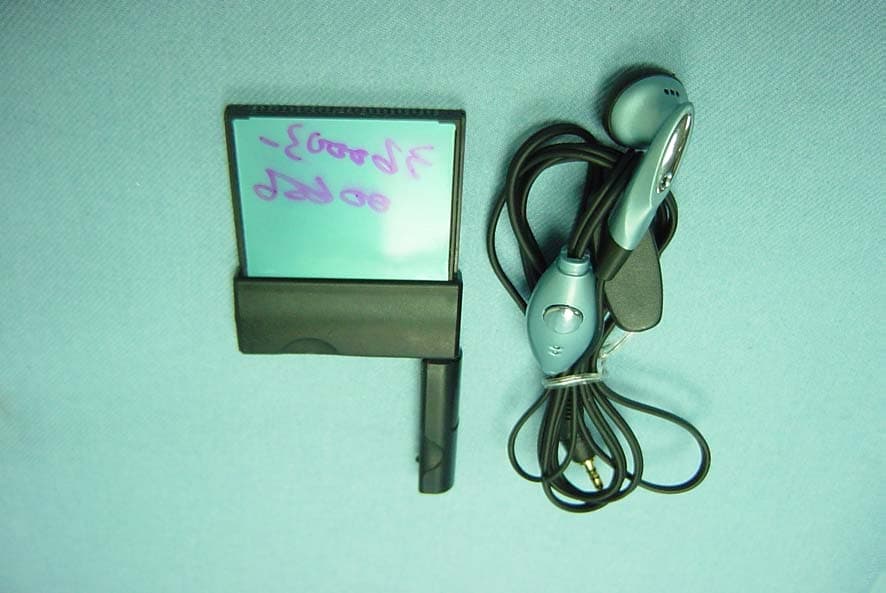
Click to zoom
Application Details
- Equipment Class
- PCB - PCS Licensed Transmitter
- Date of Grant
- Sep 16, 2003
- Application Purpose
- Original Equipment
- Date of Application
- Sep 16, 2003
- Equipment Note
- GSM/GPRS CF Card
- Frequency Range
- 1850.00000000 - 1910.00000000
- Company
- ASUSTeK Computer Inc
- Country
- Taiwan
Documents & Files
Document Text
Text extracted from the exhibit documents filed with the FCC. Open a document above to read the original.
Users Manual
GSM/GPRS CF+ Card User’s manual 1 FCC RF EXPOSURE INFORMATION Read this information before using your handset In August 1996 the Federal Communication Commission (FCC) of the United States with its action in Report and Order FCC 96-326 adopted an updated safety standard for human exposure to radio frequency (RF) electromagnetic energy emitted by FCC regulated transmitters. Those guidelines are consistent with the safety standard previously set by both U.S and international standards bodies. The design of this phone complies with the FCC guidelines and these international standards. Use only the supplied or an approved antenna. Unauthorized antennas, modifications, or attachments could impair call quality, damage the phone, or result in violation of FCC regulations. Do not use the phone with a damaged antenna. If a damaged antenna comes into contact with the skin, a minor burn may result. Please contact your local dealer for replacement antenna. Body-worn Operation This device was tested for typical body-worn operations. To comply with FCC RF exposure requirements, a minimum separation distance of 0.6 inches (1.5 cm) must be maintained between the user’s body and the handset, including the antenna. Third-party belt-clips, holsters, and similar accessories used by this device should not contain any metallic components. Body- worn accessories that do not meet these requirements may not comply with FCC RF exposure requirements and should be avoided. For more information about RF exposure, please visit the FCC website at www.fcc.gov iiGSM/GPRS CF+ Card Copyright No part of this manual, including the products and software described in it, may be reproduced, transmitted, transcribed, stored in a retrieval system, or translated into any language in any form or by any means, except documentation kept by the purchaser for backup purposes, without the express written permission of the MANUFACTURER. The MANUFACTURER provides this manual “as is” without warranty of any kind, either express or implied, including but not limited to the implied warranties or conditions of merchantability or fitness for a particular purpose. In no event shall the MANUFACTURER, its directors, officers, employees, or agents be liable for any indirect, special, incidental, or consequential damages (including damages for loss of profits, loss of business, loss of use or data, interruption of business and the like), even if the MANUFACTURER has been advised of the possibility of such damages arising from any defect or error in this manual or product. Specifications and information contained in this manual are furnished for informational use only, and are subject to change at any time without notice, and should not be construed as a commitment by the MANUFACTURER. The MANUFACTURER assumes no responsibility or liability for any errors or inaccuracies that may appear in this manual, including the products and software described in it. Product warranty or service will not be extended if: (1) the product is repaired, modified or altered, unless such repair, modification of alteration is authorized in writing by the MANUFACTURER; or (2) the serial number of the product is defaced or missing. Products and corporate names appearing in this manual may or may not be registered trademarks or copyrights of their respective companies, and are used only for identification or explanation and to the owners’ benefit, without intent to infringe. Product Name:GSM/GPRS CF+ Card Manual Edition:First edition V1 (E1290) Release Date:June 2003 GSM/GPRS CF+ Cardiii Contents Safety instructions ........................................................................... iv Chapter 1Product introduction ............................................... 1-1 Welcome! ............................................................................... 1-1 1.1Package Contents ...................................................... 1-1 1.2Specifications ............................................................. 1-2 1.3CF card parts .............................................................. 1-2 1.4LED status description ................................................ 1-2 1.5Installing and removing a SIM card ............................ 1-3 1.6Connecting to a PCMCIA adapter .............................. 1-4 1.7Installing to a notebook PC ......................................... 1-5 1.8Installing to a PDA ...................................................... 1-5 1.9Connecting a headset ................................................. 1-6 Chapter 2Notebook PC installation ........................................ 2-1 2.1System requirements .................................................. 2-1 2.2Driver installation ........................................................ 2-1 2.2.1Windows XP/2000 driver installation ............ 2-1 2.2.2Windows 98/ME driver installation ................ 2-2 2.3Installing mobile PhoneTools ...................................... 2-3 2.4mobile PhoneTools functions ...................................... 2-7 2.5Creating a GPRS connection ..................................... 2-8 Chapter 3Pocket PC installation ............................................. 3-1 3.1System requirements .................................................. 3-1 3.2Installing pocket PhoneTools ...................................... 3-1 3.3Running pocket PhoneTools ....................................... 3-5 3.4pocket PhoneTools functions ...................................... 3-7 3.4.1Main menu .................................................... 3-7 3.4.2Dialer menu .................................................. 3-8 3.5Creating a GPRS connection ..................................... 3-9 ivGSM/GPRS CF+ Card Use of radio equipment is prohibited in hospitals. DO NOT use the GSM/GPRS CF card phone or online network features in hospitals to avoid interference with medical equipment. Safety instructions When turned on, radio communication equipment units c…
Text truncated - open the document above for the full version.
Cover Letter(s)
2003/7/25 Federal Communications Commission Authorization and Evaluation Division FCC ID: MSQAGC100 Confidentiality Request Pursuant to Sections 0.457 and 0.459 of the Commission’s Rules, the Applicant hereby requests confidential treatment of information accompanying this Application as outlined below: 1. Schematics 2. Operational Description 3. Block Diagram 4. Part List 5. Turn-up Procedure 6. PCB Layout The above materials contain trade secrets and proprietary information not customarily released to the public. The public disclosure of these matters might be harmful to the Applicant and provide unjustified benefits to its competitors. The Applicant understands that pursuant to Rule 0.457, disclosure of this Application and all accompanying documentation will not be made before the date of the Grant for this application.
Cover Letter(s)
9/17/2003 Dear Steve, Regarding this question, because the area scanned is completely larger than EUT itself, therefore, even there has second peak, it would be the minor. Besides, attached please find the test plots that were done on Sept. 5. Thanks a lot for your help. Best Regards, Lucy (Typo resent) Hi Lucy, Q1 to Q9 and Q11 OK, But I still cannot find the proper info for Q10 as described below, Question #10: P33 & P49 of NB-COMPAQ test plot shown second peak and is not completely captured, please re-measure and supply the plot. P33 now transfer to P36 of “(AGC-100)SAR Test plot_NB-COMPAQ-2.pdf” remains no change. P49 now transfer to P53 of “(AGC-100)SAR Test plot_NB-COMPAQ-2.pdf” and measurement area remains no change. Please enlarge your scan area to include the second peak. If question is not clear to you, please call me to discuss this issue. Also, please supply the system verification plots for extra plot generated. Best regards, Steve -----Original Message----- Steve Cheng <[email protected]> 2003/09/13 08:38 AM ???: "'[email protected]'" <[email protected]> ????: "'Jonson (E-mail)'" <[email protected]>, Mike Kuo <[email protected]> ??: RE: ??: Re: ASUSTek AN03T3182 TCB question From: [email protected] [mailto:[email protected]] Sent: Friday, September 12, 2003 4:52 AM To: Steve Cheng Cc: Jonson (E-mail); Mike Kuo Subject: ??: Re: ASUSTek AN03T3182 TCB question Dear Steve, Below please find the reply for the SAR portion, Q8-11. Q8, we have verified the low and mid channels and please refer the SAR test report and plot for details. Q9, "senser-surface:0mm" here is refer to the configurations of 1, 2,5,6 : touch mode, setting EUT directly connect to the phantom. Besides, we have renamed each test plot which may be easy understood and compared with the SAR test report. Q10-11, we have verified test and updated as attached SAR test report. Please help to review them and issue the grant a.s.a.p if there has no other problems, thank you. Best Regards, Lucy -----Original Message----- From: [email protected] [mailto:[email protected]] Sent: Wednesday, September 03, 2003 1:57 AM To: Steve Cheng Cc: Jonson (E-mail); Lucy (E-mail); Mike Kuo Subject: ??: Re: ASUSTEK AN03T3182 Hi Steve, Please refer to the below for the answer to Q1-Q7. For Q1, it's caused by measurement equipment deviation. For Q2, we have verified all modes with each type (here refers to PDA and NB) of host, finding out the worst position to perform the test with rest hosts as the result recorded in the report. For testing with PDAs, we tested EUT with NEC's PDA firstly as the data shew in page 52 that wost case found was EUT pol. in V, Antenna Pol. in H and EUT antenna pol. in Z. Then for other type of PDAs, we all set them at the same position of V/H/Z for final testing. The above rule also applied to Notebook PC. 9/17/2003 Therefore, please recheck it again and hope that will be enough. For Q3, please find attached for the internal photos. For Q4, the plastic basket doesn't contain metal material and its characteristic just as test wooden table that won't interfere the RF measurement. For Q5, please refer the attached for the operational description. For Q6, please refer the attached for the antenna spec. For Q7, please take page 22 as example that the test result was recorded in the below of the test plot. the 26dBc bandwidth is the range between two arrow. The display line here mean nothing. Best Regards, Lucy RT for project: AN03T3182 Notice_content -EMC portion- Question #1: p11 of EMC report shown highest power measured is 28.97dBm. But summary indicated 28.95 dBm, and SAR tested to 28.95 dBm. Please clarify. Question #2: On P49 section 9 "Field strength of spur radiation measurement", Please justify that full test on one host and then test only VHZ or VVX configuration on rest of two hosts is sufficient to demonstrate the compliance. Question #3: Please remove the RF shielding and re-take the internal photo. Question #4: Please confirm that the plastic basket used in the EMC test for raising up the EUT has proper RF characteristic and will not interfere the measurement. Question #5: OP description does not have proper info Question #6: Antenna spec needs to be re-scanned. It is not readable. Question #7: P 22, emission bandwidth test, display line is not in -26dBc position Steve Cheng <[email protected]> 2003/08/28 09:54 AM ???: "Jonson (E-mail)" <[email protected]>, "Lucy (E-mail)" <[email protected]> ????: Mike Kuo <[email protected]> ??: Re: ASUSTEK AN03T3182 9/17/2003 -SAR portion- Question #8: P25 shown full test on ASUS PDA and result with 1.2w/kg maximum on test setup configuration 2, but partial test on NEC shown different SAR pattern and maximum shift to configuration 1 with a maximum of 1.4w/kg. Since SAR reading is close to the limit and no enough test data to support that the high channel is the highest SAR configuration for NEC platform, please supply extra test data on Low and Mid channel to clarify this concern. Question #9: Please explain the setup purpose of "Sensor-Surface: 0mm (Fix Surface)" on each test plot. Question #10: P33 & P49 of NB-COMPAQ test plot shown second peak and is not completely captured, please re-measure and supply the plots. Question #11: The ET3DV6 SN:1577 mentioned on p6 of test report does not matching the probe info supplied. Please correct. The items indicated above must be submitted before processing can continue on the above referenced application. Failure to provide the requested information within 60 days of the original e-mail date may result in application dismissal and forfeiture of the filing fee. Also, please note that partial responses increase processing time and should not be submitted. Any questions about the content of this correspondence should be directed to the e-mail address listed below the name of the sender. Best Regards Steve Cheng Compliance Certification Services 561F Monterey Road Morgan Hill, CA 95037 Te…
Text truncated - open the document above for the full version.
External Photos
C&C Laboratory Co. Ltd. REPORT NO: B30613204-RP FCC ID: MSQAGC100 DATE: July 21, 2003 Page 77 Rev. 00 APPENDIX 2 EXTERNAL PHOTOGRPHS OF EUT C&C Laboratory Co. Ltd. REPORT NO: B30613204-RP FCC ID: MSQAGC100 DATE: July 21, 2003 Page 78 Rev. 00 All View of EUT Front View of EUT
Internal Photos
C&C Laboratory Co. Ltd. REPORT NO: B30613204-RP FCC ID: MSQAGC100 DATE: July 21, 2003 Page 79 Rev. 00 APPENDIX 3 INTERNAL PHOTOGRPHS OF EUT C&C Laboratory Co. Ltd. REPORT NO: B30613204-RP FCC ID: MSQAGC100 DATE: July 21, 2003 Page 80 Rev. 00 Internal of EUT --- 1 Internal of EUT --- 2 C&C Laboratory Co. Ltd. REPORT NO: B30613204-RP FCC ID: MSQAGC100 DATE: July 21, 2003 Page 81 Rev. 00 Internal of EUT --- 3 Internal of EUT --- 4 C&C Laboratory Co. Ltd. REPORT NO: B30613204-RP FCC ID: MSQAGC100 DATE: July 21, 2003 Page 82 Rev. 00 Internal of EUT --- 5 Internal of EUT --- 6 C&C Laboratory Co. Ltd. REPORT NO: B30613204-RP FCC ID: MSQAGC100 DATE: July 21, 2003 Page 83 Rev. 00 Internal of EUT --- 7 Internal of EUT --- 8
Operational Description
Antenna Gain Test Report Company: ASUS Model No.: GSM/GPRS CF+Card Test Condition: Free Space
RF Exposure Info
Date/Time: 07/03/03 09:55:14 Test Laboratory: The name of your organization File Name: D1800V2 SN-3.da4 D1800V2 SN-3 DUT: Dipole 1800 MHz; Type: D1800V2; Serial: D1800V2 - SN:2d062 Program: System Performance Check at1800MHz Communication System: CW1800; Frequency: 1800 MHz;Duty Cycle: 1:1 Medium: HSL1800 (σ = 1.3643 mho/m, ε r = 38.7023, ρ = 1000 kg/m 3 ) Air Temperature 25.5 deg C ; Liquid Temperature 25.6deg C Phantom section: Flat Section DASY4 Configuration: z Probe: ET3DV6 - SN1762; ConvF(5.4, 5.4, 5.4); Calibrated: 3/31/2003 z Sensor-Surface: 4mm (Mechanical And Optical Surface Detection) Sensor-Surface: 0mm (Fix Surface) z Electronics: DAE3 Sn558; Calibrated: 3/7/2003 z Phantom: SAM 34; Type: SAM V4.0; Serial: TP-1150 z Measurement SW: DASY4, V4.1 Build 47; Postprocessing SW: SEMCAD, V1.6 Build 115 Pin=250mW,d=10mm/Area Scan (7x7x1): Measurement grid: dx=15mm, dy=15mm Reference Value = 95.5 V/m Power Drift = -0.008 dB Maximum value of SAR = 11.2 mW/g Pin=250mW,d=10mm/Zoom Scan (5x5x7)/Cube 0: Measurement grid: dx=7.5mm, dy=7.5mm, dz=5mm Peak SAR (extrapolated) = 17.1 W/kg SAR(1 g) = 10 mW/g; SAR(10 g) = 5.26 mW/g Reference Value = 95.5 V/m Power Drift = -0.008 dB Maximum value of SAR = 11.2 mW/g Pin=250mW,d=10mm/Z Scan (1x1x21): Measurement grid: dx=20mm, dy=20mm, dz=5mm Reference Value = 95.5 V/m Power Drift = -0.02 dB Maximum value of SAR = 9.56 mW/g Page1 0 dB = 11.2mW/g Page2 Date/Time: 07/07/03 10:01:45 Test Laboratory: The name of your organization File Name: D1800V2 SN-3.da4 D1800V2 SN-3 DUT: Dipole 1800 MHz; Type: D1800V2; Serial: D1800V2 - SN:2d062 Program: System Performance Check at1800MHz Communication System: CW1800; Frequency: 1800 MHz;Duty Cycle: 1:1 Medium: HSL1800 (σ = 1.35612 mho/m, ε r = 39.5551, ρ = 1000 kg/m 3 ) Air Temperature 25.7 deg C; Liquid Temperature 25.5 deg C Phantom section: Flat Section DASY4 Configuration: z Probe: ET3DV6 - SN1762; ConvF(5.4, 5.4, 5.4); Calibrated: 3/31/2003 z Sensor-Surface: 4mm (Mechanical And Optical Surface Detection) Sensor-Surface: 0mm (Fix Surface) z Electronics: DAE3 Sn558; Calibrated: 3/7/2003 z Phantom: SAM 12; Type: SAM V4.0; Serial: TP-1271 z Measurement SW: DASY4, V4.1 Build 47; Postprocessing SW: SEMCAD, V1.6 Build 115 Pin=250mW,d=10mm/Area Scan (7x7x1): Measurement grid: dx=15mm, dy=15mm Reference Value = 93.6 V/m Power Drift = -0.05 dB Maximum value of SAR = 10.6 mW/g Pin=250mW,d=10mm/Zoom Scan (5x5x7)/Cube 0: Measurement grid: dx=7.5mm, dy=7.5mm, dz=5mm Peak SAR (extrapolated) = 16 W/kg SAR(1 g) = 9.41 mW/g; SAR(10 g) = 4.95 mW/g Reference Value = 93.6 V/m Power Drift = -0.05 dB Maximum value of SAR = 10.6 mW/g Pin=250mW,d=10mm/Z Scan (1x1x21): Measurement grid: dx=20mm, dy=20mm, dz=5mm Reference Value = 93.6 V/m Power Drift = -0.05 dB Maximum value of SAR = 8.77 mW/g Page1 0 dB = 10.6mW/g Page2 Date/Time: 07/10/03 10:21:56 Test Laboratory: The name of your organization File Name: D1800V2 SN-3.da4 D1800V2 SN-3 DUT: Dipole 1800 MHz; Type: D1800V2; Serial: D1800V2 - SN:2d062 Program: System Performance Check at1800MHz Communication System: CW1800; Frequency: 1800 MHz;Duty Cycle: 1:1 Medium: HSL1800 (σ = 1.39 mho/m, ε r = 38.37, ρ = 1000 kg/m 3 ) Air Temperature 26.0 deg C ; Liquid Temperature 25.8 deg C Phantom section: Flat Section DASY4 Configuration: - Probe: ET3DV6 - SN1762; ConvF(5.4, 5.4, 5.4); Calibrated: 3/31/2003 - Sensor-Surface: 4mm (Mechanical And Optical Surface Detection) Sensor-Surface: 0mm (Fix Surface) - Electronics: DAE3 Sn558; Calibrated: 3/7/2003 - Phantom: SAM 34; Type: SAM V4.0; Serial: TP-1150 - Measurement SW: DASY4, V4.1 Build 47; Postprocessing SW: SEMCAD, V1.6 Build 115 Pin=250mW,d=10mm/Area Scan (7x7x1): Measurement grid: dx=15mm, dy=15mm Reference Value = 91.2 V/m Power Drift = 0.03 dB Maximum value of SAR = 10.3 mW/g Pin=250mW,d=10mm/Zoom Scan (5x5x7)/Cube 0: Measurement grid: dx=7.5mm, dy=7.5mm, dz=5mm Peak SAR (extrapolated) = 17.3 W/kg SAR(1 g) = 10 mW/g; SAR(10 g) = 5.24 mW/g Reference Value = 91.2 V/m Power Drift = 0.03 dB Maximum value of SAR = 11.2 mW/g Pin=250mW,d=10mm/Z Scan (1x1x21): Measurement grid: dx=20mm, dy=20mm, dz=5mm Reference Value = 91.2 V/m Power Drift = 0.03 dB Maximum value of SAR = 9.68 mW/g Page1 0 dB = 11.2mW/g Page2 Date/Time: 07/11/03 09:59:42 Test Laboratory: The name of your organization File Name: D1800V2 SN-3.da4 D1800V2 SN-3 DUT: Dipole 1800 MHz; Type: D1800V2; Serial: D1800V2 - SN:2d062 Program: System Performance Check at1800MHz Communication System: CW1800; Frequency: 1800 MHz;Duty Cycle: 1:1 Medium: HSL1800 (σ = 1.3774 mho/m, ε r = 38.6972, ρ = 1000 kg/m 3 ) Air Temperature 25.9 deg C ; Liquid Temperature 25.8 deg C Phantom section: Flat Section DASY4 Configuration: - Probe: ET3DV6 - SN1762; ConvF(5.4, 5.4, 5.4); Calibrated: 3/31/2003 - Sensor-Surface: 4mm (Mechanical And Optical Surface Detection) Sensor-Surface: 0mm (Fix Surface) - Electronics: DAE3 Sn558; Calibrated: 3/7/2003 - Phantom: SAM 34; Type: SAM V4.0; Serial: TP-1150 - Measurement SW: DASY4, V4.1 Build 47; Postprocessing SW: SEMCAD, V1.6 Build 115 Pin=250mW,d=10mm/Area Scan (7x7x1): Measurement grid: dx=15mm, dy=15mm Reference Value = 90.9 V/m Power Drift = -0.05 dB Maximum value of SAR = 10 mW/g Pin=250mW,d=10mm/Zoom Scan (5x5x7)/Cube 0: Measurement grid: dx=7.5mm, dy=7.5mm, dz=5mm Peak SAR (extrapolated) = 16.4 W/kg SAR(1 g) = 9.62 mW/g; SAR(10 g) = 5.05 mW/g Reference Value = 90.9 V/m Power Drift = -0.05 dB Maximum value of SAR = 10.8 mW/g Pin=250mW,d=10mm/Z Scan (1x1x21): Measurement grid: dx=20mm, dy=20mm, dz=5mm Reference Value = 90.9 V/m Power Drift = -0.06 dB Maximum value of SAR = 9.08 mW/g Page1 0 dB = 10.8mW/g Page2 Date/Time: 07/12/03 11:26:35 Test Laboratory: The name of your organization File Name: D1800V2 SN-3.da4 D1800V2 SN-3 DUT: Dipole 1800 MHz; Type: D1800V2; Serial: D1800V2 - SN:2d062 Program: System Performance Check at1800MHz Communication System: CW1800; Frequency: 1800 MHz;Duty Cycle: 1:1 Medium: HSL1800 (σ = 1.368 mho/m, ε r = 38.5892, ρ = 1000 kg/m 3 ) Air Temp…
Text truncated - open the document above for the full version.
RF Exposure Info
AGC-100 IN TOSHIBA NOTEBOOK (WORST CASE) Page1 Date/Time: 07/12/03 11:25:40 Test Laboratory: The name of your organization File Name: gsm-0mm-h.da4 gsm-0mm-h DUT: AGC100; Type: CF CARD; Serial: ID:MSQAGC100 Program: gsm=0mm Communication System: GSM1900; Frequency: 1909.8 MHz;Duty Cycle: 1:8 Medium: HSL1900 (σ = 1.581 mho/m, ε r = 50.967, ρ = 1000 kg/m 3 ) Phantom section: Flat Section Air Temp 26 deg C ; Liquid Temp 25.9 deg C DASY4 Configuration: z Probe: ET3DV6 - SN1762; ConvF(5, 5, 5); Calibrated: 3/31/2003 z Sensor-Surface: 4mm (Mechanical And Optical Surface Detection) Sensor-Surface: 0mm (Fix Surface) z Electronics: DAE3 Sn558; Calibrated: 3/7/2003 z Phantom: SAM 12; Type: SAM V4.0; Serial: TP-1271 z Measurement SW: DASY4, V4.1 Build 47; Postprocessing SW: SEMCAD, V1.6 Build 115 gsm high-h/Area Scan (5x9x1): Measurement grid: dx=15mm, dy=15mm Reference Value = 13.1 V/m Power Drift = -0.07 dB Maximum value of SAR = 0.324 mW/g gsm high-h/Zoom Scan (5x5x7)/Cube 0: Measurement grid: dx=7.5mm, dy=7.5mm, dz=5mm Peak SAR (extrapolated) = 0.515 W/kg SAR(1 g) = 0.326 mW/g; SAR(10 g) = 0.197 mW/g Reference Value = 13.1 V/m Power Drift = -0.07 dB Maximum value of SAR = 0.346 mW/g gsm high-h/Zoom Scan (5x5x7)/Cube 1: Measurement grid: dx=7.5mm, dy=7.5mm, dz=5mm Peak SAR (extrapolated) = 0.428 W/kg SAR(1 g) = 0.262 mW/g; SAR(10 g) = 0.154 mW/g Reference Value = 13.1 V/m Power Drift = -0.07 dB Maximum value of SAR = 0.283 mW/g gsm high-h/Z Scan (1x1x21): Measurement grid: dx=20mm, dy=20mm, dz=5mm Reference Value = 13.1 V/m Power Drift = -0.04 dB Maximum value of SAR = 0.279 mW/g Page1 Page2 Date/Time: 07/12/03 14:45:05 Test Laboratory: The name of your organization File Name: gprs-0mm-h.da4 gprs-0mm-h DUT: AGC100; Type: CF CARD; Serial: ID:MSQAGC100 Program: flat Communication System: GPRS1900; Frequency: 1909.8 MHz;Duty Cycle: 1:4 Medium: HSL1900 (σ = 1.581 mho/m, ε r = 50.967, ρ = 1000 kg/m 3 ) Phantom section: Flat Section Air Temp 26 deg C ; Liquid Temp 25.9 deg C DASY4 Configuration: z Probe: ET3DV6 - SN1762; ConvF(5, 5, 5); Calibrated: 3/31/2003 z Sensor-Surface: 4mm (Mechanical And Optical Surface Detection) Sensor-Surface: 0mm (Fix Surface) z Electronics: DAE3 Sn558; Calibrated: 3/7/2003 z Phantom: SAM 12; Type: SAM V4.0; Serial: TP-1271 z Measurement SW: DASY4, V4.1 Build 47; Postprocessing SW: SEMCAD, V1.6 Build 115 gprs high-h/Area Scan (5x8x1): Measurement grid: dx=15mm, dy=15mm Reference Value = 15.2 V/m Power Drift = -0.01 dB Maximum value of SAR = 0.448 mW/g gprs high-h/Zoom Scan (5x5x7)/Cube 0: Measurement grid: dx=7.5mm, dy=7.5mm, dz=5mm Peak SAR (extrapolated) = 0.666 W/kg SAR(1 g) = 0.405 mW/g; SAR(10 g) = 0.245 mW/g Reference Value = 15.2 V/m Power Drift = -0.01 dB Maximum value of SAR = 0.428 mW/g gprs high-h/Zoom Scan (5x5x7)/Cube 1: Measurement grid: dx=7.5mm, dy=7.5mm, dz=5mm Peak SAR (extrapolated) = 0.47 W/kg SAR(1 g) = 0.266 mW/g; SAR(10 g) = 0.153 mW/g Reference Value = 15.2 V/m Power Drift = -0.01 dB Maximum value of SAR = 0.303 mW/g gprs high-h/Z Scan (1x1x21): Measurement grid: dx=20mm, dy=20mm, dz=5mm Reference Value = 15.2 V/m Power Drift = -0.03 dB Maximum value of SAR = 0.347 mW/g Page1 Page2 Date/Time: 07/12/03 11:26:13 Test Laboratory: The name of your organization File Name: gsm-0mm-v.da4 gsm-0mm-v DUT: AGC-100; Type: TOSHIBA; Serial: ID:MSQAGC100 Program: gsm=0mm Communication System: GSM1900; Frequency: 1909.8 MHz;Duty Cycle: 1:8 Medium: HSL1900 (σ = 1.581 mho/m, ε r = 50.967, ρ = 1000 kg/m 3 ) Phantom section: Flat Section Air Temp 26 deg C ; Liquid Temp 25.9 deg C DASY4 Configuration: z Probe: ET3DV6 - SN1762; ConvF(5, 5, 5); Calibrated: 3/31/2003 z Sensor-Surface: 4mm (Mechanical And Optical Surface Detection) Sensor-Surface: 0mm (Fix Surface) z Electronics: DAE3 Sn558; Calibrated: 3/7/2003 z Phantom: SAM 12; Type: SAM V4.0; Serial: TP-1271 z Measurement SW: DASY4, V4.1 Build 47; Postprocessing SW: SEMCAD, V1.6 Build 115 gsm high-v/Area Scan (5x9x1): Measurement grid: dx=15mm, dy=15mm Reference Value = 9.14 V/m Power Drift = -0.007 dB Maximum value of SAR = 0.194 mW/g gsm high-v/Z Scan (1x1x21): Measurement grid: dx=20mm, dy=20mm, dz=5mm Reference Value = 9.14 V/m Power Drift = 0.0008 dB Maximum value of SAR = 0.104 mW/g gsm high-v/Zoom Scan (5x5x7)/Cube 0: Measurement grid: dx=7.5mm, dy=7.5mm, dz=5mm Peak SAR (extrapolated) = 0.313 W/kg SAR(1 g) = 0.194 mW/g; SAR(10 g) = 0.115 mW/g Reference Value = 9.14 V/m Power Drift = -0.007 dB Maximum value of SAR = 0.207 mW/g Page1 Page2 Date/Time: 07/12/03 15:09:56 Test Laboratory: The name of your organization File Name: gprs-0mm-v.da4 gprs-0mm-v DUT: AGC-100; Type: TOSHIBA; Serial: ID:MSQAGC100 Program: flat Communication System: GPRS1900; Frequency: 1909.8 MHz;Duty Cycle: 1:4 Medium: HSL1900 (σ = 1.581 mho/m, ε r = 50.967, ρ = 1000 kg/m 3 ) Phantom section: Flat Section Air Temp 26 deg C ; Liquid Temp 25.9 deg C DASY4 Configuration: z Probe: ET3DV6 - SN1762; ConvF(5, 5, 5); Calibrated: 3/31/2003 z Sensor-Surface: 4mm (Mechanical And Optical Surface Detection) Sensor-Surface: 0mm (Fix Surface) z Electronics: DAE3 Sn558; Calibrated: 3/7/2003 z Phantom: SAM 12; Type: SAM V4.0; Serial: TP-1271 z Measurement SW: DASY4, V4.1 Build 47; Postprocessing SW: SEMCAD, V1.6 Build 115 gprs high-v/Area Scan (5x7x1): Measurement grid: dx=15mm, dy=15mm Reference Value = 12.3 V/m Power Drift = 0.2 dB Maximum value of SAR = 0.305 mW/g gprs high-v/Zoom Scan (5x5x7)/Cube 0: Measurement grid: dx=7.5mm, dy=7.5mm, dz=5mm Peak SAR (extrapolated) = 0.465 W/kg SAR(1 g) = 0.291 mW/g; SAR(10 g) = 0.176 mW/g Reference Value = 12.3 V/m Power Drift = 0.2 dB Maximum value of SAR = 0.312 mW/g gprs high-v/Z Scan (1x1x21): Measurement grid: dx=20mm, dy=20mm, dz=5mm Reference Value = 12.3 V/m Power Drift = 0.2 dB Maximum value of SAR = 0.276 mW/g Page1 Page2 Date/Time: 07/12/03 17:23:36 Test Laboratory: C&C Labratory CO., Ltd File Name: gsm15mm=h.da4 gsm15mm=h DUT: AGC100; Type: CF CARD; Serial: ID:MSQAGC100 Program: flat 15mm Communication Syst…
Text truncated - open the document above for the full version.
RF Exposure Info
AGC-100 IN COMPAQ NOTEBOOK Page1 Date/Time: 07/10/03 17:34:02 Test Laboratory: C&C Labratory CO., Ltd File Name: newgsm-0mm-h.da4 newgsm-0mm-h DUT: AGC100; Type: CF CARD; Serial: ID:MSQAGC100 Program: gsm=0mm Communication System: GSM1900; Frequency: 1850.2 MHz;Duty Cycle: 1:8 Medium: HSL1900 (σ = 1.594 mho/m, ε r = 51.36, ρ = 1000 kg/m 3 ) Phantom section: Flat Section Air Temp 26 deg C ; Liquid Temp 25.8 deg C DASY4 Configuration: z Probe: ET3DV6 - SN1762; ConvF(5, 5, 5); Calibrated: 3/31/2003 z Sensor-Surface: 4mm (Mechanical And Optical Surface Detection) Sensor-Surface: 0mm (Fix Surface) z Electronics: DAE3 Sn558; Calibrated: 3/7/2003 z Phantom: SAM 12; Type: SAM V4.0; Serial: TP-1271 z Measurement SW: DASY4, V4.1 Build 47; Postprocessing SW: SEMCAD, V1.6 Build 115 gsm 512-h/Area Scan (11x7x1): Measurement grid: dx=15mm, dy=15mm Reference Value = 7.44 V/m Power Drift = -0.08 dB Maximum value of SAR = 0.187 mW/g gsm 512-h/Zoom Scan (5x5x7)/Cube 0: Measurement grid: dx=7.5mm, dy=7.5mm, dz=5mm Peak SAR (extrapolated) = 0.293 W/kg SAR(1 g) = 0.173 mW/g; SAR(10 g) = 0.0998 mW/g Reference Value = 7.44 V/m Power Drift = -0.08 dB Maximum value of SAR = 0.188 mW/g gsm 512-h/Z Scan (1x1x21): Measurement grid: dx=20mm, dy=20mm, dz=5mm Reference Value = 7.44 V/m Power Drift = -0.1 dB Maximum value of SAR = 0.0902 mW/g Page1 Page2 Date/Time: 07/10/03 17:34:02 Test Laboratory: C&C Labratory CO., Ltd File Name: newgsm-0mm-h.da4 newgsm-0mm-h DUT: AGC100; Type: CF CARD; Serial: ID:MSQAGC100 Program: gsm=0mm Communication System: GSM1900; Frequency: 1880 MHz;Duty Cycle: 1:8 Medium: HSL1900 (σ = 1.594 mho/m, ε r = 51.36, ρ = 1000 kg/m 3 ) Phantom section: Flat Section Air Temp 26 deg C ; Liquid Temp 25.8 deg C DASY4 Configuration: z Probe: ET3DV6 - SN1762; ConvF(5, 5, 5); Calibrated: 3/31/2003 z Sensor-Surface: 4mm (Mechanical And Optical Surface Detection) Sensor-Surface: 0mm (Fix Surface) z Electronics: DAE3 Sn558; Calibrated: 3/7/2003 z Phantom: SAM 12; Type: SAM V4.0; Serial: TP-1271 z Measurement SW: DASY4, V4.1 Build 47; Postprocessing SW: SEMCAD, V1.6 Build 115 gsm 661-h/Area Scan (6x6x1): Measurement grid: dx=15mm, dy=15mm Reference Value = 7.03 V/m Power Drift = 0.1 dB Maximum value of SAR = 0.167 mW/g gsm 661-h/Zoom Scan (5x5x7)/Cube 0: Measurement grid: dx=7.5mm, dy=7.5mm, dz=5mm Peak SAR (extrapolated) = 0.288 W/kg SAR(1 g) = 0.164 mW/g; SAR(10 g) = 0.0922 mW/g Reference Value = 7.03 V/m Power Drift = 0.1 dB Maximum value of SAR = 0.178 mW/g gsm 661-h/Z Scan (1x1x21): Measurement grid: dx=20mm, dy=20mm, dz=5mm Reference Value = 7.03 V/m Power Drift = 0.06 dB Maximum value of SAR = 0.0798 mW/g Page1 Page2 Date/Time: 07/10/03 17:34:02 Test Laboratory: C&C Labratory CO., Ltd File Name: newgsm-0mm-h.da4 newgsm-0mm-h DUT: AGC100; Type: CF CARD; Serial: ID:MSQAGC100 Program: gsm=0mm Communication System: GSM1900; Frequency: 1909.8 MHz;Duty Cycle: 1:8 Medium: HSL1900 (σ = 1.594 mho/m, ε r = 51.36, ρ = 1000 kg/m 3 ) Phantom section: Flat Section Air Temp 26 deg C ; Liquid Temp 25.8 deg C DASY4 Configuration: z Probe: ET3DV6 - SN1762; ConvF(5, 5, 5); Calibrated: 3/31/2003 z Sensor-Surface: 4mm (Mechanical And Optical Surface Detection) Sensor-Surface: 0mm (Fix Surface) z Electronics: DAE3 Sn558; Calibrated: 3/7/2003 z Phantom: SAM 12; Type: SAM V4.0; Serial: TP-1271 z Measurement SW: DASY4, V4.1 Build 47; Postprocessing SW: SEMCAD, V1.6 Build 115 gsm 810-h/Area Scan (6x6x1): Measurement grid: dx=15mm, dy=15mm Reference Value = 7.43 V/m Power Drift = 0.02 dB Maximum value of SAR = 0.177 mW/g gsm 810-h/Zoom Scan (5x5x7)/Cube 0: Measurement grid: dx=7.5mm, dy=7.5mm, dz=5mm Peak SAR (extrapolated) = 0.327 W/kg SAR(1 g) = 0.181 mW/g; SAR(10 g) = 0.099 mW/g Reference Value = 7.43 V/m Power Drift = 0.02 dB Maximum value of SAR = 0.196 mW/g gsm 810-h/Z Scan (1x1x21): Measurement grid: dx=20mm, dy=20mm, dz=5mm Reference Value = 7.43 V/m Power Drift = 0.004 dB Maximum value of SAR = 0.163 mW/g Page1 Page2 Date/Time: 07/10/03 17:31:50 Test Laboratory: C&C Labratory CO., Ltd File Name: new=gprs-0mm-h.da4 new=gprs-0mm-h DU…
Text truncated - open the document above for the full version.
Contact Information
Applicant
Jackson Yen(Associate Vice President)
Test Firm
Compliance Certification Services Inc.Kurt Chen
Technical Specifications
| # | Rule Parts | Frequency Range | Power Output | Emission | Tolerance |
|---|---|---|---|---|---|
| 1 | 24E | 1.85 GHz - 1.91 GHz | 1.905 W | 317KGXW | 2.5000000000 ppm |
Other Applications from ASUSTeK Computer Inc

MSQ-GC701
Aug 21, 2026Wireless Gaming Controller
Equipment Class
DSS - Part 15 Spread Spectrum TransmitterMSQMPDONGLE3
Aug 18, 2026WIRELESS DONGLE
Equipment Class
DTS - Digital Transmission System
MSQ-GC701D
Aug 13, 2026USB Wireless Dongle
Equipment Class
DSS - Part 15 Spread Spectrum TransmitterMSQ-CM3206DM4A
May 27, 2026Chromebook/Notebook PC
Equipment Class
DCD - Part 15 Low Power Transmitter Below 1705 kHz
MSQ-GST868003
Apr 03, 2026MODULE-WIRELESS CHRG
Equipment Class
DCD - Part 15 Low Power Transmitter Below 1705 kHz