MSQB2200BGNOTEBOOK P.C.
ASUSTeK Computer Inc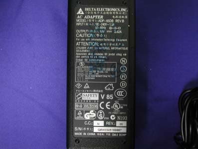
Click to zoom
Application Details
- Equipment Class
- DTS - Digital Transmission System
- Date of Grant
- Jun 14, 2004
- Application Purpose
- Original Equipment
- Date of Application
- Jun 14, 2004
- Equipment Note
- NOTEBOOK P.C.
- Frequency Range
- 2412.00000000 - 2462.00000000
- Company
- ASUSTeK Computer Inc
- Country
- Taiwan
Documents & Files
Document Text
Text extracted from the exhibit documents filed with the FCC. Open a document above to read the original.
Users Manual
Copyright Information No part of this manual, including the products and software described in it, may be reproduced, transmitted, tran- scribed, stored in a retrieval system, or translated into any language in any form or by any means, except documen- tation kept by the purchaser for backup purposes, without the express written permission of ASUSTeK COM- PUTER INC. (“ASUS”). ASUS PROVIDES THIS MANUAL “AS IS” WITHOUT WARRANTY OF ANY KIND, EITHER EXPRESS OR IMPLIED, INCLUDING BUT NOT LIMITED TO THE IMPLIED WARRANTIES OR CONDITIONS OF MER- CHANTABILITY OR FITNESS FOR A PARTICULAR PURPOSE. IN NO EVENT SHALL ASUS, ITS DIREC- TORS, OFFICERS, EMPLOYEES OR AGENTS BE LIABLE FOR ANY INDIRECT, SPECIAL, INCIDENTAL, OR CONSEQUENTIAL DAMAGES (INCLUDING DAMAGES FOR LOSS OF PROFITS, LOSS OF BUSI- NESS, LOSS OF USE OR DATA, INTERRUPTION OF BUSINESS AND THE LIKE), EVEN IF ASUS HAS BEEN ADVISED OF THE POSSIBILITY OF SUCH DAMAGES ARISING FROM ANY DEFECT OR ERROR IN THIS MANUAL OR PRODUCT. Product warranty or service will not be extended if: (1) the product is repaired, modified or altered, unless such repair, modification of alteration is authorized in writing by ASUS; or (2) the serial number of the product is defaced or missing. Products and corporate names appearing in this manual may or may not be registered trademarks or copyrights of their respective companies, and are used only for identification or explanation and to the owners’ benefit, without intent to infringe. SPECIFICATIONS AND INFORMATION CONTAINED IN THIS MANUAL ARE FURNISHED FOR INFOR- MATIONAL USE ONLY, AND ARE SUBJECT TO CHANGE AT ANY TIME WITHOUT NOTICE, AND SHOULD NOT BE CONSTRUED AS A COMMITMENT BY ASUS. ASUS ASSUMES NO RESPONSIBILITY OR LI- ABILITY FOR ANY ERRORS OR INACCURACIES THAT MAY APPEAR IN THIS MANUAL, INCLUDING THE PRODUCTS AND SOFTWARE DESCRIBED IN IT. Copyright © 2003 ASUSTeK COMPUTER INC. All Rights Reserved. Limitation of Liability Circumstances may arise where because of a default on ASUS’ part or other liability, you are entitled to recover damages from ASUS. In each such instance, regardless of the basis on which you are entitled to claim damages from ASUS, ASUS is liable for no more than damages for bodily injury (including death) and damage to real property and tangible personal property; or any other actual and direct damages resulted from omission or failure of performing legal duties under this Warranty Statement, up to the listed contract price of each product. ASUS will only be responsible for or indemnify you for loss, damages or claims based in contract, tort or infringe- ment under this Warranty Statement. This limit also applies to ASUS’ suppliers and its reseller. It is the maximum for which ASUS, its suppliers, and your reseller are collectively responsible. UNDER NO CIRCUMSTANCES IS ASUS LIABLE FOR ANY OF THE FOLLOWING: (1) THIRD-PARTY CLAIMS AGAINST YOU FOR DAMAGES; (2) LOSS OF, OR DAMAGE TO, YOUR RECORDS OR DATA; OR (3) SPECIAL, INCIDENTAL, OR INDIRECT DAMAGES OR FOR ANY ECONOMIC CONSEQUENTIAL DAMAGES (INCLUDING LOST PROFITS OR SAVINGS), EVEN IF ASUS, ITS SUPPLIERS OR YOUR RE- SELLER IS INFORMED OF THEIR POSSIBILITY. 1 Product Name:Notebook PC Hardware Manual Revision:1 E1660 Release Date:May 2004 Notebook PC Hardware User’s Manual FEDERAL COMMUNICATIONS COMMISSION INTERFERENCE STATEMENT This equipment has been tested and found to comply with the limits for a Class B digital device, pursuant to Part 15 of the FCC Rules. These limits are designed to provide reasonable protection against harmful interference in a residential installation. This equipment generates, uses and can radiate radio frequency energy and, if not installed and used in accordance with the instructions, may cause harmful interference to radio communications. However, there is no guarantee that interference will not occur in a particular installation. If this equipment does cause harmful interference to radio or television reception, which can be determined by turning the equipment off and on, the user is encouraged to try to correct the interference by one or more of the following measures: -- Reorient or relocate the receiving antenna. -- Increase the separation between the equipment and receiver. -- Connect the equipment into an outlet on a circuit different from that to which the receiver is connected. -- Consult the dealer or an experienced radio/TV technician for help. CAUTION: Any changes or modifications not expressly approved by the grantee of this device could void the user's authority to operate the equipment. FCC RF Radiation Exposure Statement This equipment complies with FCC RF radiation exposure limits set forth for an uncontrolled environment. This equipment should be installed and operated with a minimum distance of 20cm between the radiator and your body. Safety Statements Federal Communications Commission Statement This device complies with FCC Rules Part 15. Operation is subject to the following two conditions: • This device may not cause harmful interference, and • This device must accept any interference received, including interference that may cause undesired operation. This equipment has been tested and found to comply with the limits for a class B digital device, pursuant to Part 15 of the Federal Communications Commission (FCC) rules. These limits are designed to provide reasonable protection against harmful interference in a residential installation. This equipment generates, uses, and can radiate radio frequency energy and, if not installed and used in accordance with the instruc- tions, may cause harmful interference to radio communications. However, there is no guarantee that inter- ference will not occur in a particular installation. If this equipment does cause harmful interference to radio or television reception, which can be determined by turning the equipment off and on, the user is encouraged to try to correct the interference by one or more of the following measures: • Reorient or relocate the re…
Text truncated - open the document above for the full version.
Attestation Statements
ASUSTek COMPUTER INC. FCC ID.: MSQB2200BG 4FL., No. 150, Li-Te Rd., Peitou, Taipei, Taiwan, R.O.C. Tel: +886 2 2894-3447 Federal Communications Commission Jun. 15, 2004 Authorization and Evaluation Division ATTESTATION FCC ID: MSQB2200BG Product: Notebook P.C. Model : A3400N, A3500N, A3800N, A3F00N, A3400Nc, A3500Nc, , A3800Nc, A3F00Nc We don't provide any controls or software to allow operation outside the USA frequency band when we sell this product in USA. Sincerely, Andy Chiu / Product Manager ASUSTeK COMPUTER INC.
Block Diagram
Intel / WM3B2200BG Block Diagrams Option1 miniPCI Ramon2 Radio Transceiver Ardon 2 MAC AND ANALOG PHY Differential I and Q RF PA P2023 BAND PASS FILTER T/R-DIVERSITY RF SWITCH BANDPASS FILTER BAND PASS FILTER BALUN BALUN EEPROM Rx Tx 1.2V2.8V3.3V 2.9V MainAux 40 MHz Xtal 40MHz Clock 1.8V 2.8V3.3V LNA VCO 2.9V 2.8V Option2 mPCI Connector Page 4 Ardon 2 MAC & Analog PHY Page 5,6 & 7 Voltage Regulators & DC/ DC Converter Page 3 Ramon 2 Radio Transceiver Page 8 T/R- Diversity Switch Page 11 Main Aux Antenna Ports Tx RF Rx RF Tx BB Rx BB Transceiver Control Front End Control Front End Bias Transceiver Bias MAC Bias Bias Interface EEPROM Page 5 Tx PA Page 9 Rx LNA Page 10 Ext. VCO Page 13 BB Filter Loop Filter Xtal Circuit Page 12 Intel / WM3B2200BG Option 3 mPCI Connector Ardon 2 MAC & Analog PHY Voltage Regulators & DC/ DC Converter Ramon 2 Radio Transceiver RF Front End Main Aux Antenna Ports Tx RF Rx RF Tx BB Rx BB Transceiver Control Front End Control Front End Bias Transceiver Bias MAC Bias Bias Interface EEPROM
Cover Letter(s)
ASUSTek COMPUTER INC. FCC ID.: MSQB2200BG 4FL., No. 150, Li-Te Rd., Peitou, Taipei, Taiwan, R.O.C. Tel: +886 2 2894-3447 ASUSTeK COMPUTER INC. 4FL., No. 150, Li-Te Rd., Peitou, Taipei, Taiwan, R.O.C. Tel: +886 2 2894 3447 Fax:+886 2 2890 7965 Federal Communications Commission Jun. 15, 2004 Authorization and Evaluation Division Confidentiality Request Pursuant to Sections 0.457 and 0.459 of the Commission’s Rules, the Applicant Hereby requests confidential treatment of information accompanying this Application As outlined below: Schematics The above materials contain trade secrets and proprietary information not customarily Released to the public. The public disclosure of these matters might be harmful to the Applicant and provide unjustified benefits to its competitors. The Applicant understands that pursuant to Rule 0.457, disclosure of this Application and all accompanying documentation will not be made before the date of the Grant for this application. Sincerely, Andy Chiu / Product Manager ASUSTeK COMPUTER INC.
External Photos
Report No.: 045L082FI Page : 1 of 11 Version:1.0 Attachment 2 : EUT Detailed Photographs (1) EUT Photo (2) EUT Photo Report No.: 045L082FI Page : 2 of 11 Version:1.0 (3) EUT Photo (4) EUT Photo Report No.: 045L082FI Page : 3 of 11 Version:1.0 (5) EUT Photo (6) EUT Photo Report No.: 045L082FI Page : 4 of 11 Version:1.0 (7) EUT Photo (8) EUT Photo
ID Label/Location Info
ASUSTek COMPUTER INC. FCC ID.: MSQB2200BG 4FL., No. 150, Li-Te Rd., Peitou, Taipei, Taiwan, R.O.C. Tel: +886 2 2894-3447 FCC ID AND DoC Label The FCC ID and DoC Label will be placed on the equipment as shown in the photograph below. Notebook P.C. ATIO Model No.: A3400N, A3500N, A3800N, A3F00N, A3400Nc, A3500Nc, A3800Nc, A3F00Nc TESTED TO COMPLY WITH FCC STANDARDS FOR HOME OR OFFICE USE S/N: Made in Taiwan Notebook P.C. Model No.: A3400N, A3500N, A3800N, A3F00N, A3400Nc, A3500Nc, A3800Nc, A3F00Nc F F C C C C I I D D : : M M S S Q Q AB B 2 2 2 2 0 0 0 0BG This device complies with Part 15 of the FCC Rules. Operation is subject to the following two conditions: (1) this device may not cause harmful interference and (2) this device must accept any interference received, including interference that may cause undesired operation. S/N: Made in Taiwan
Operational Description
Report No. 045L082FI Page: 5 of 64 Version:1.0 1.2. Operational Description EUT is a Notebook P.C. with 11 channels. This device provided four kinds of transmitting speed 1, 2, 5.5 and 11Mbps. The device of RF carrier is DQPSK, DB PSK and CCK (IEEE 802.11b) or eight kinds of transmitting speed 6, 9, 12, 18, 24, 36, 48 and 54Mbps. The device of RF carrier is OFDM (IEEE 802.11g). The device adapts direct sequence spread spectrum modulation. The antenna was Connector provides diversity function to improve the receiving function. This Notebook P.C., compliant with IEEE 802.11b and IEEE 802.11g, is a high-efficiency Wireless LAN adapter. It allows your computer to connect to a wireless network and to share resources, such as files or printers without being bound to the network wires. Operation in 2.4GHz Direst Sequence Spread Spectrum (DSSS) radio transmission, the Notebook P.C. Wired Equivalent Protection (WEP) algorithm is used. In addition, its standard compliance ensures that it can communicate with any IEEE 802.11b and IEEE 802.11g network. Test Mode: Mode 1: Transmitter 802.11b Mode 1: Transmitter 802.11g
RF Exposure Info
Report No. : ES/2004/60002 Page : 1 of 63 TEST REPORT Equipment Under Test : Notebook P.C. Model No. : A3400N,A3500N,A3800N,A3F00N,A3400Nc,A3500Nc, A3800Nc,A3F00Nc FCC ID : MSQB2200BG Applicant : ASUSTeK COMPUTER INC. Address of Applicant : 4FL., No. 150, Li-Te Rd., Peitou, Taipei, Taiwan, R.O.C. Date of Receipt : 2004.05.27 Date of Test(s) : 2004.06.04-2004.06.08 Date of Issue : 2004.06.09 Standards: FCC OET Bulletin 65 supplement C, ANSI/IEEE C95.1 , C95.3 In the configuration tested, the EUT complied with the standards specified above. Remarks: This report details the results of the testing carried out on one sample, the results contained in this test report do not relate to other samples of the same product. The manufacturer should ensure that all products in series production are in conformity with the product sample detailed in this report. This report may only be reproduced and distributed in full. If the product in this report is used in any configuration other than that detailed in the report, the manufacturer must ensure the new system complies with all relevant standards. Any mention of SGS Taiwan E&E Services or testing done by SGS Taiwan E&E Services in connection with distribution or use of the product described in this report must be approved by SGS Taiwan E&E Services in writing. Tested by : Dikin Yang Date : 2004/06/09 Approved by : Robert Chang Date : 2004/06/09 Report No. : ES/2004/60002 Page : 2 of 63 Contents 1. General Information 1.1 Testing Laboratory 4 1.2 Details of Applicant 4 1.3 Description of EUT(s) 4 1.4 Test Environment 5 1.5 Operation description 5 1.6 Evaluation procedures 6 1.7 The SAR Measurement System 7 1.8 System Components 9 1.9 SAR System Verification 10 1.10 Tissue Simulant Fluid for the Frequency Band 2.4 to 2.5 GHz 11 1.11 Test Standards and Limits 12 2. Instruments List 14 3. Summary of Results 15 4. Measurements 19 802.11b Configuration 1 4.1.1 Back of the LCD panel position, lowest channel 19 4.1.2 Back of the LCD panel position, middle channel 20 4.1.3 Back of the LCD panel position, highest channel 21 Configuration 2 4.1.4 LCD panel position, lowest channel 22 4.1.5 LCD panel position, middle channel 23 4.1.6 LCD panel position, highest channel 24 Configuration 3 4.1.7 Back of the LCD panel position, lowest channel 25 4.1.8 Back of the LCD panel position, middle channel 26 4.1.9 Back of the LCD panel position, highest channel 27 Configuration 4 4.1.10 LCD panel position, lowest channel 28 4.1.11 LCD panel position, middle channel 29 4.1.12 LCD panel position, highest channel 30 Configuration 5 4.1.13 Bottom face position, lowest channel 31 4.1.14 Bottom face position, middle channel 32 4.1.15 Bottom face position, highest channel 33 802.11g Configuration 1 4.2.1 Back of the LCD panel position, lowest channel 34 4.2.2 Back of the LCD panel position, middle channel 35 4.2.3 Back of the LCD panel position, highest channel 36 Configuration 2 4.2.4 LCD panel position, lowest channel 37 Report No. : ES/2004/60002 Page : 3 of 63 4.2.5 LCD panel position, middle channel 38 4.2.6 LCD panel position, highest channel 39 Configuration 3 4.2.7 Back of the LCD panel position, lowest channel 40 4.2.8 Back of the LCD panel position, middle channel 41 4.2.9 Back of the LCD panel position, highest channel 42 Configuration 4 4.2.10 LCD panel position, lowest channel 43 4.2.11 LCD panel position, middle channel 44 4.2.12 LCD panel position, highest channel 45 Configuration 5 4.2.13 Bottom face position, lowest channel 46 4.2.14 Bottom face position, middle channel 47 4.2.15 Bottom face position, highest channel 48 4.3 System Performance Validation 49 APPENDIX 1. Photographs of Test Setup 50 2. Photographs of EUT 54 3. Probe Calibration certificate 57 4. Uncertainty Analysis 61 5. Phantom description 62 6. System Validation from Original equipment supplier 63 Report No. : ES/2004/60002 Page : 4 of 63 1. General Information 1.1 Testing Laboratory SGS Taiwan Ltd. 1F, No. 134, Wukung Road, Wuku industrial zone Taipei county , Taiwan , R.O.C. Telephone : +886-2-2299-3279 Fax : +886-2-2298-2698 Internet : http://www.sgs.com.tw 1.2 Details of Applicant Name : ASUSTeK COMPUTER INC. Address : 4FL., No. 150, Li-Te Rd., Peitou, Taipei, Taiwan, R.O.C. 1.3 Description of EUT(s) Equipment Type Notebook P.C. Test Procedure FCC OET Bulletin 65, Supplement C TX Frequency range 2412-2462 MHz FCC ID MSQB2200BG Model No. A3400N,A3500N,A3800N,A3F00N, A3400Nc,A3500Nc,A3800Nc,A3F00Nc Number Of Channel 11 Modulation Direct Sequence Spread Spectrum (DSSS) 802.11b 802.11g Transfer Rate 11 Mbps 6 Mbps 802.11b 802.11g Max. SAR Measured 0.496 W/kg 0.423 W/kg Main Auxiliary Antenna Gain -0.3 dB -1.8 dB Antenna Type PIFA I/O Port Mini PCI Report No. : ES/2004/60002 Page : 5 of 63 Power Supply 19Vdc from AC adapter NOTE: 1. The mini PCI card, which brand is Intel and the model name is WM3B2200BG is specified to this EUT. 2. The EUT is powered by the following adapter: Brand DELTA Model ADP-65DB Input 100-240Vac 1.5A 50-60Hz Output 19Vdc 3.42A 3. For more detailed features description, please refer to the manufacturer's specifications or User's Manual. 1.4 Test Environment Ambient temperature : 22.1° C Tissue Simulating Liquid : 21.4° C Relative Humidity : 62 % 1.5 Operation Configuration 802.11b 802.11g Channel Frequency Under Test And Its Conducted Output Power(Peak) 16.74 dBm(2412MHz) 16.26 dBm(2437MHz) 15.77 dBm(2462MHz) 15.01 dBm(2412MHz) 16.18 dBm(2437MHz) 14.19 dBm(2462MHz) Antenna Configuration Internal Antenna Antenna Position The Antennas are located at both sides of the LCD; the right Antenna is the main antenna, and the left one is the auxiliary. EUT Power Source From The Host Equipment HOST Power Source Fully Charged Battery The following test configurations have been applied in this test report: Main Antenna Configuration 1: The back of the LCD Panel of EUT contact to the flat phantom. The Report No. : ES/2004/60002 Page : 6 of 63 transmitted antenna of the EUT located under th…
Text truncated - open the document above for the full version.
Test Report
Report No. 045L082FI Page: 1 of 64 Version:1.0 Test Report Product Name : Notebook P.C. Model No. : A3400N, A3500N, A3800N, A3F00N, A3400Nc, A3500Nc, A3800Nc, A3F00Nc FCC ID : MSQB2200BG Applicant : ASUSTeK COMPUTER INC. Address : 4FL., No. 150, Li-Te Rd., Peitou, Taipei, Taiwan, R.O.C. Date of Receipt : May. 12, 2004 Date of Test : May. 16, 2004 Report No. : 045L082FI The test results relate only to the samples tested. The test report shall not be reproduced except in full without the written approval of QuieTek Corporation. This report must not be used to claim product endorsement by NVLAP any agency of the U.S. Government Report No. 045L082FI Page: 2 of 64 Version:1.0 Test Report Certification Test Date: May. 16, 2004 Report No. : 045L082FI Test results relate only to the samples tested. The test report shall not be reproduced except in full without the written approval of QuieTek Corporation. This report must not be used to claim product endorsement by NVLAP any agency of the U.S. Government Product Name : Notebook P.C. Applicant : ASUSTeK COMPUTER INC. Address : 4FL., No. 150, Li-Te Rd., Peitou, Taipei, Taiwan, R.O.C. Manufacturer : ASUSTeK COMPUTER INC. Model No. : A3400N, A3500N, A3800N, A3F00N, A3400Nc, A3500Nc, A3800Nc, A3F00Nc Rated Voltage : AC 120V/60Hz Trade Name : ASUS Measurement Standard : FCC CFR Title 47 Part 15 Subpart C: 2003 Measurement Procedure : ANSI C63.4: 2001 Test Result : Complied Documented By : ( Anita Chou ) Tested By : ( Geddy Jeng ) Approved By : ( Gene Chang ) Accredited by NIST (NVLAP) NVLAP Lab Code: 200533-0 Report No. 045L082FI Page: 3 of 64 Version:1.0 TABLE OF CONTENTS Description Page 1. GENERAL INFORMATION .....................................................................................................4 1.1. EUT Description............................................................................................................................4 1.2. Operational Description ................................................................................................................5 1.3. Tested System Datails....................................................................................................................6 1.4. Configuration of tested System .....................................................................................................6 1.5. EUT Exercise Software .................................................................................................................6 1.6. Test Facility ...................................................................................................................................7 2. Conducted Emission....................................................................................................................8 2.1. Test Equipment..............................................................................................................................8 2.2. Test Setup ......................................................................................................................................8 2.3. Limits ............................................................................................................................................8 2.4. Test Procedure ...............................................................................................................................9 2.5. Uncertainty ....................................................................................................................................9 2.6. Test Result of Conducted Emission.............................................................................................10 3. Peak Power Output ...................................................................................................................22 3.1. Test Equipment............................................................................................................................22 3.2. Test Setup ....................................................................................................................................22 3.3. Limits ..........................................................................................................................................22 3.4. Uncertainty ..................................................................................................................................22 3.5. Test Result of Peak Power Output...............................................................................................23 4. Radiated Emission .....................................................................................................................25 4.1. Test Equipment............................................................................................................................25 4.2. Test Setup ....................................................................................................................................25 4.3. Limits ..........................................................................................................................................26 4.4. Test Procedure .............................................................................................................................27 4.5. Uncertainty ..................................................................................................................................27 4.6. Test Result of Radiated Emission................................................................................................28 5. Band Edge ..................................................................................................................................40 5.1. Test Equipment............................................................................................................................40 5.2. Test Setup ..........................................................................................................................…
Text truncated - open the document above for the full version.
Test Setup Photos
Report No.: 045L082FI Page : 1 of 3 Version:1.0 Attachment 1: EUT Test Setup Photographs Front View of Conducted Test Back View of Conducted Test Report No.: 045L082FI Page : 2 of 3 Version:1.0 Front View of Radiated Test Back View of Radiated Test Report No.: 045L082FI Page : 3 of 3 Version:1.0 Front View of Radiated Test (Horn) Back View of Radiated Test (Horn)
Contact Information
Applicant
Jackson Yen(Associate Vice President)
Test Firm
Quietek CorporationGene Chang
Technical Specifications
| # | Rule Parts | Frequency Range | Power Output |
|---|---|---|---|
| 1 | 15C | 2.41 GHz - 2.46 GHz | 47.00 mW |
Other Applications from ASUSTeK Computer Inc

MSQ-GC701
Aug 21, 2026Wireless Gaming Controller
Equipment Class
DSS - Part 15 Spread Spectrum TransmitterMSQMPDONGLE3
Aug 18, 2026WIRELESS DONGLE
Equipment Class
DTS - Digital Transmission System
MSQ-GC701D
Aug 13, 2026USB Wireless Dongle
Equipment Class
DSS - Part 15 Spread Spectrum TransmitterMSQ-CM3206DM4A
May 27, 2026Chromebook/Notebook PC
Equipment Class
DCD - Part 15 Low Power Transmitter Below 1705 kHz
MSQ-GST868003
Apr 03, 2026MODULE-WIRELESS CHRG
Equipment Class
DCD - Part 15 Low Power Transmitter Below 1705 kHz