MSQK013CASUS Tablet
ASUSTeK Computer Inc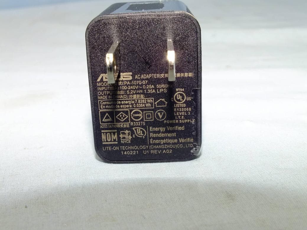
Click to zoom
Application Details
- Equipment Class
- DXX - Part 15 Low Power Communication Device Transmitter
- Date of Grant
- Jan 20, 2015
- Application Purpose
- Original Equipment
- Date of Application
- Jan 20, 2015
- Equipment Note
- ASUS Tablet
- Frequency Range
- 13.56000000 - 13.56000000
- Company
- ASUSTeK Computer Inc
- Country
- Taiwan
Documents & Files
Document Text
Text extracted from the exhibit documents filed with the FCC. Open a document above to read the original.
Users Manual
User Guide E10063 ASUS Tablet First Edition / January 2015 Charging your device Ensure to fully charge your ASUS Tablet before using it in battery mode for extended periods. Remember that the power adapter charges your ASUS Tablet as long as it is plugged into an AC power source. Be aware that it takes much longer to charge the ASUS Tablet when it is in use. IMPORTANT! Do not leave the ASUS Tablet connected to the power supply once it is fully charged. ASUS Tablet is not designed to be left connected to the power supply for extended periods of time. Airplane precautions Contact your airline provider to learn about related inflight services that can be used and restrictions that must be followed when using your ASUS Tablet in-flight. IMPORTANT! You can send your ASUS Tablet through x-ray machines (used on items placed on conveyor belts), but do not expose them from magnetic detectors and wands. Safety precautions This ASUS Tablet should only be used in enviroments with ambient temperatures between 0°C to 35°C (32°F to 95°F). Long time exposure to extremely high or low temperature may quickly deplete and shorten the battery life. To ensure the battery’s optimal performance, ensure that it is exposed within the recommended environment temperature. ASUS Tablet 3 Package contents NOTES: • If any of the items is damaged or missing, contact your retailer. • The bundled power adapter varies with country or region. ASUS TabletPower adapter ASUS Tablet Micro USB cableTechnical documentations and warranty card ASUS Tablet 4 Your ASUS Tablet Front camera Touch screen panel Front view ASUS Tablet 5 Rear view * The microSD card slot supports microSD, microSDHC, and microSDXC card formats. Micro USB 2.0 port MicroSD card slot* Speaker/Headset port Microphone Audio speaker Rear camera NFC Power button Volume button ASUS Tablet 6 Charging your ASUS Tablet To charge your ASUS Tablet: Connect the micro USB cable to the power adapter. Plug the micro USB connector into your ASUS Tablet. Plug the power adapter into a grounded power outlet. Charge your ASUS Tablet for eight (8) hours before using it in battery mode for the first time. ASUS Tablet 7 IMPORTANT! • Use only the bundled power adapter and micro USB cable to charge your ASUS Tablet. Using a different power adapter may damage your ASUS Tablet. • Peel the protective film off from the power adapter and micro USB cable before charging the ASUS Tablet to prevent risk or injury. • Ensure that you plug the power adapter to the correct power outlet with the correct input rating. The output voltage of this adapter is DC 5.2 V, 1.35 A. • When using your ASUS Tablet while plugged-in to a power outlet, the grounded power outlet must be near the unit and easily accessible. • Do not place objects on top of your ASUS Tablet. NOTES: • Your ASUS Tablet can be charged via the USB port on the computer only when it is in sleep mode (screen off ) or turned off. • Charging through the USB port of a computer may take longer time to complete. • If your computer does not provide enough power for charging your ASUS Tablet, charge your ASUS Tablet via the grounded power outlet instead. ASUS Tablet 8 Appendices Federal Communications Commission Statement This device complies with FCC Rules Part 15. Operation is subject to the following two conditions: • This device may not cause harmful interference. • This device must accept any interference received, including interference that may cause undesired operation. This equipment has been tested and found to comply with the limits for a class B digital device, pursuant to Part 15 of the Federal Communications Commission (FCC) rules. These limits are designed to provide reasonable protection against harmful interference in a residential installation. This equipment generates, uses, and can radiate radio frequency energy and, if not installed and used in accordance with the instructions, may cause harmful interference to radio communications. However, there is no guarantee that interference will not occur in a particular installation. If this equipment causes harmful interference to radio or television reception, which can be determined by turning the equipment off and on, the user is encouraged to try to correct the interference by doing one or more of the following measures: • Reorient or relocate the receiving antenna. • Increase the separation between the equipment and receiver. • Connect the equipment into an outlet on a circuit different from that to which the receiver is connected. ASUS Tablet 9 • Consult the dealer or an experienced radio/TV technician for help. Changes or modifications not expressly approved by the party responsible for compliance could void the user‘s authority to operate the equipment. The antenna(s) used for this transmitter must not be co- located or operating in conjunction with any other antenna or transmitter. RF Exposure Information (SAR) This device meets the government’s requirements for exposure to radio waves. This device is designed and manufactured not to exceed the emission limits for exposure to radio frequency (RF) energy set by the Federal Communications Commission of the U.S. Government. The exposure standard employs a unit of measurement known as the Specific Absorption Rate, or SAR. The SAR limit set by the FCC is 1.6 W/kg. Tests for SAR are conducted using standard operating positions accepted by the FCC with the EUT tr ansmitting at the specified power level in different channels. The highest SAR value for the device as reported to the FCC is 1.14 W/kg when placed next to the body. Note: The country code selection is for non-US model only and is not a vailable to all US model. Per FCC regulation, all WiFi product marketed in US must fixed to US operation channels only. ASUS Tablet 10 Canada, Industry Canada (IC) Notices This Class B digital apparatus complies with Canadian ICES-003, RSS-210, and CAN ICES-3(B)/NMB-3(B). This device complies with Industry Canada license-exempt RSS standar…
Text truncated - open the document above for the full version.
Attestation Statements
DFS client device channel plan and software operational declaration Date: January 20, 2015 We, ASUSTeK Computer Inc, declare that the device, FCC ID: MSQK013C Model Name: K013C, does not have “Ad Hoc on non-US frequencies” and/or “on DFS frequencies. Also, the client software and associated drivers will not initiate any transmission on DFS frequencies without initiation by a master. This includes restriction on transmissions for beacons and support for ad-hoc peer-to-peer modes. Below is the channel / frequency plan for the device Also, on DFS channels, the WLAN driver in the device operates under the control of an AP at all times, except when in ad-hoc mode, on US non-DFS channels. The device passively scans DFS frequencies until a master device is detected. The control of this functionality is not accessible to anyone under any conditions. Furthermore, the firmware is protected by special signature and CRC checksum. Signature and CRC checksum will be calculated and verified before firmware upgrade. Unauthorized modification to firmware will lead the failure of verification thus firmware upgrade is not allowed. Sincerely yours, CH 1 2 3 4 5 6 7 8 9 10 11 Frequency (MHz) 2412 2417 242224272432243724422447 2452 24572462 Scan Type Active Active Active Active Active Active Active Active Active Active Active CH 36 38 40 42 44 48 52 54 56 58 60 Frequency (MHz) 5180 5190 520052105220524052605270 5280 52905300 Scan Type Active Active Active Active Active Active Passive Passive Passive Passive Passive CH 62 64 Frequency (MHz) 5310 5320 Scan Type Passive Passive CH 100 102 104 106 108 110 112 116 132 134 136 Frequency (MHz) 5500 5510 552055305540555055605580 5660 56705680 Scan Type Passive Passive Passive Passive Passive Passive Passive Passive Passive Passive Passive CH 140 Frequency (MHz) 5700 Scan Type Passive CH 149 151 153 155 157 159 161 165 Frequency (MHz) 5745 5755 576557755785579558055825 Scan Type Active Active Active Active Active Active Active Active
Cover Letter(s)
4F, No. 150, Li-Te Rd., Peitou, Taipei, Taiwan Date: January 20, 2015 Federal Communications Commission 7435 Oakland Mills Road - Gate A Columbia, Maryland 21046 Subject: Request for Confidentiality FCC ID: MSQK013C To Whom It May Concern, Pursuant to the provisions of Sections 0.457 and 0.459 of Commission’s rules (47CFR§§0.457, 0.459), we are requesting the Commission to withhold the following attachments as confidential document from public disclosure indefinitely. z Schematic Diagram z Block Diagram z Parts List z Operational Description z Software Operational Description Above mentioned document contains detailed system and equipment description are considered as proprietary information in operation of the equipment. The public disclosure of above documents might be harmful to our company and would give competitor an unfair advantage in the market. In additional to above mentioned documents, pursuant to Public Notice DA 04-1705 of the Commission’ s policy, in order to comply with the marketing regulations in 47 CFT §2.803 and the importation rules in 47 CFR §2.1204, while ensuring that business sensitive information remains confidential until the actual marketing of newly authorized devices. We are requesting the commission to grant short-term confidentiality request on the following attachments until 180 days after the Grant Date of Equipment Authorizations. External Photos Internal Photos Test Setup Photos Users Manual It is our understanding that all measurement test reports, FCC ID label format and correspondent during certification review process cannot be granted as confidential documents and those information will be available for public review once the grant of equipment authorization is issued. Best Regards,
External Photos
Page 1 of 17 Report No.: 141216C25 CONSTRUCTION PHOTOS OF EUT Page 2 of 17 Report No.: 141216C25 Page 3 of 17 Report No.: 141216C25 Page 4 of 17 Report No.: 141216C25 Page 5 of 17 Report No.: 141216C25 Page 6 of 17 Report No.: 141216C25 Page 7 of 17 Report No.: 141216C25
ID Label/Location Info
FCC ID: MSQK013C IC: 3568A-K013C Back cover of EUT Label Location
ID Label/Location Info
38.97mm 16.03 mm 5 mm 5 mm F5 E187242 6mm ME176CE US/CAN (美加) F5 E187242 ASUS Tablet Made in China Model: K013C Input: + 5.2V 1.35A, 7W FCC ID: MSQK013C IC: 3568A-K013C 000000000000
Internal Photos
Page 8 of 17 Report No.: 141216C25 Page 9 of 17 Report No.: 141216C25 Page 10 of 17 Report No.: 141216C25 Page 11 of 17 Report No.: 141216C25 Page 12 of 17 Report No.: 141216C25 Page 13 of 17 Report No.: 141216C25 Page 14 of 17 Report No.: 141216C25 Page 15 of 17 Report No.: 141216C25 Page 16 of 17 Report No.: 141216C25 Page 17 of 17 Report No.: 141216C25
RF Exposure Info
FCC SAR Test Report Report Format Version 5.0.0 Page No. : 1 of 27 Report No. : SA141216C25 Issued Date : Jan. 12, 2015 FCC SAR Test Report Report No. : SA141216C25 Applicant : ASUSTek COMPUTER INC. Address : 4F, No. 150, LI-TE Rd., PEITOU, TAIPEI 112, TAIWAN Product : ASUS Tablet FCC ID : MSQK013C Brand : ASUS Model No. : K013C Standards : FCC 47 CFR Part 2 (2.1093) / IEEE C95.1:1992 / IEEE 1528:2003 IEEE 1528a-2005 / KDB 865664 D01 v01r03 KDB 248227 D01 v01r02 / KDB 447498 D01 v05r02 / KDB 616217 D04 v01r01 Sample Received Date : Dec. 16, 2014 Date of Testing : Dec. 29, 2014 ~ Dec. 31, 2014 CERTIFICATION: The above equipment have been tested by Bureau Veritas Consumer Products Services (H.K.) Ltd., Taoyuan Branch – Lin Kou Laboratories, and found compliance with the requirement of the above standards. The test record, data evaluation & Equipment Under Test (EUT) configurations represented herein are true and accurate accounts of the measurements of the sample’s SAR characteristics under the conditions specified in this report. It should not be reproduced except in full, without the written approval of our laboratory. The client should not use it to claim product certification, approval, or endorsement by TAF or any government agencies. Prepared By : Vera Huang / Specialist Approved By : Gordon Lin / Assistant Manager This report is for your exclusive use. Any copying or replication of this report to or for any other person or entity, or use of our name or trademark, is permitted only with our prior written permission. This report sets forth our findings solely with respect to the test samples identified herein. The results set forth in this report are not indicative or representative of the quality or characteristics of the lot from which a test sample was taken or any similar or identical product unless specifically and expressly noted. Our report includes all of the tests requested by you and the results thereof based upon the information that you provided to us. You have 60 days from date of issuance of this report to notify us of any material error or omission caused by our negligence, provided, however, that such notice shall be in writing and shall specifically address the issue you wish to raise. A failure to raise such issue within the prescribed time shall constitute your unqualified acceptance of the completeness of this report, the tests conducted and the correctness of the report contents. Unless specific mention, the uncertainty of measurement has been explicitly taken into account to declare the compliance or non-compliance to the specification. FCC SAR Test Report Report Format Version 5.0.0 Page No. : 2 of 27 Report No. : SA141216C25 Issued Date : Jan. 12, 2015 Table of Contents Release Control Record ............................................................................................................................................................... 3 1. Summary of Maximum SAR Value ....................................................................................................................................... 4 2. Description of Equipment Under Test ................................................................................................................................. 5 3. SAR Measurement System ................................................................................................................................................... 6 3.1 Definition of Specific Absorption Rate (SAR) ............................................................................................................... 6 3.2 SPEAG DASY System ................................................................................................................................................. 6 3.2.1 Robot .................................................................................................................................................................. 7 3.2.2 Probes ................................................................................................................................................................ 8 3.2.3 Data Acquisition Electronics (DAE) .................................................................................................................... 8 3.2.4 Phantoms ........................................................................................................................................................... 9 3.2.5 Device Holder ................................................................................................................................................... 10 3.2.6 System Validation Dipoles ................................................................................................................................ 10 3.2.7 Tissue Simulating Liquids ................................................................................................................................. 11 3.3 SAR System Verification ............................................................................................................................................ 14 3.4 SAR Measurement Procedure ................................................................................................................................... 15 3.4.1 Area & Zoom Scan Procedure ......................................................................................................................... 15 3.4.2 Volume Scan Procedure ................................................................................................................................... 15 3.4.3 Power Drift Monitoring ...................................................................................................................................... 16 3.4.4 Spatial Peak SAR Evaluation ........................................................................................................................... 16 3.4.5 SAR Averaged Methods ....................…
Text truncated - open the document above for the full version.
Test Report
Report No.: RF141216C25-2 1 of 68 Report Format Version 5.1.0 FCC TEST REPORT (BLUETOOTH) REPORT NO.: RF141216C25-2 MODEL NO.: K013C FCC ID: MSQK013C RECEIVED: Dec. 11, 2014 TESTED: Dec. 11, 2014 ~ Dec. 26, 2014 ISSUED: Jan. 14, 2015 APPLICANT: ASUSTek COMPUTER INC. ADDRESS: 4F, No. 150, LI-TE Rd., PEITOU, TAIPEI 112, TAIWAN ISSUED BY: Bureau Veritas Consumer Products Services (H.K.) Ltd., Taoyuan Branch LAB ADDRESS: No. 47-2, 14th Ling, Chia Pau Vil., Lin Kou Dist., New Taipei City, Taiwan ( R.O.C ) TEST LOCATION: No. 19, Hwa Ya 2nd Rd, Wen Hwa Tsuen, Kwei Shan Hsiang, Taoyuan Hsien 333, Taiwan, R.O.C. This report is for your exclusive use. Any copying or replication of this report to or for any other person or entity, or use of our name or trademark, is permitted only with our prior written permission. This report sets forth our findings solely with respect to the test samples identified herein. The results set forth in this report are not indicative or representative of the quality or characteristics of the lot from which a test sample was taken or any similar or identical product unless specifically and expressly noted. Our report includes all of the tests requested by you and the results thereof based upon the information that you provided to us. You have 60 days from date of issuance of this report to notify us of any material error or omission caused by our negligence, provided, however, that such notice shall be in writing and shall specifically address the issue you wish to raise. A failure to raise such issue within the prescribed time shall constitute your unqualified acceptance of the completeness of this report, the tests conducted and the correctness of the report contents. Unless specific mention, the uncertainty of measurement has been explicitly taken into account to declare the compliance or non-compliance to the specification. This report should not be used by the client to claim product certification, approval, or endorsement by TAF or any government agencies. Report No.: RF141216C25-2 2 of 68 Report Format Version 5.1.0 TABLE OF CONTENTS RELEASE CONTROL RECORD ..............................................................................................................5 1. CERTIFICATION ..................................................................................................................................6 2. SUMMARY OF TEST RESULTS .........................................................................................................7 2.1 MEASUREMENT UNCERTAINTY...............................................................................................8 3. GENERAL INFORMATION ..................................................................................................................9 3.1 GENERAL DESCRIPTION OF EUT ............................................................................................9 3.2 DESCRIPTION OF TEST MODES ............................................................................................ 11 3.2.1 TEST MODE APPLICABILITY AND TESTED CHANNEL DETAIL .............................. 12 3.3 DESCRIPTION OF SUPPORT UNITS ..................................................................................... 16 3.3.1 CONFIGURATION OF SYSTEM UNDER TEST ......................................................... 16 3.4 GENERAL DESCRIPTION OF APPLIED STANDARDS .......................................................... 17 4. TEST TYPES AND RESULTS (FOR BLUETOOTH EDR) ............................................................... 18 4.1 RADIATED EMISSION AND BANDEDGE MEASUREMENT .................................................. 18 4.1.1 LIMITS OF RADIATED EMISSION AND BANDEDGE MEASUREMENT ................... 18 4.1.2 TEST INSTRUMENTS ................................................................................................. 19 4.1.3 TEST PROCEDURES ................................................................................................. 20 4.1.4 DEVIATION FROM TEST STANDARD ....................................................................... 20 4.1.5 TEST SETUP ............................................................................................................... 21 4.1.6 EUT OPERATING CONDITIONS ................................................................................ 22 4.1.7 TEST RESULTS........................................................................................................... 23 4.2 CONDUCTED EMISSION MEASUREMENT ........................................................................... 27 4.2.1 LIMITS OF CONDUCTED EMISSION MEASUREMENT ........................................... 27 4.2.2 TEST INSTRUMENTS ................................................................................................. 27 4.2.3 TEST PROCEDURES ................................................................................................. 28 4.2.4 DEVIATION FROM TEST STANDARD ....................................................................... 28 4.2.5 TEST SETUP ............................................................................................................... 29 4.2.6 EUT OPERATING CONDITIONS ................................................................................ 29 4.2.7 TEST RESULTS........................................................................................................... 30 4.3 NUMBER OF HOPPING FREQUENCY USED ........................................................................ 32 4.3.1 LIMIT OF HOPPING FREQUENCY USED ................................................................. 32 4.3.2 TEST SETUP ............................................................................................................... 32 4.3.3 TEST INSTRUMENTS ................................................................................................. 32 4.3.4 TEST PROCEDURE .....................................................................................…
Text truncated - open the document above for the full version.
Test Report
Report No.: RF141216C25 1 of 51 Report Format Version 5.2.1 FCC TEST REPORT (15.247) REPORT NO.: RF141216C25 MODEL NO.: K013C FCC ID: MSQK013C RECEIVED: Dec. 16, 2014 TESTED: Dec. 23, 2014 ~ Dec. 26, 2014 ISSUED: Jan. 14, 2015 APPLICANT: ASUSTek COMPUTER INC. ADDRESS: 4F, No. 150, LI-TE Rd., PEITOU, TAIPEI 112, TAIWAN ISSUED BY: Bureau Veritas Consumer Products Services (H.K.) Ltd., Taoyuan Branch LAB ADDRESS: No. 47-2, 14th Ling, Chia Pau Vil., Lin Kou Dist., New Taipei City, Taiwan ( R.O.C ) TEST LOCATION: No. 19, Hwa Ya 2nd Rd, Wen Hwa Tsuen, Kwei Shan Hsiang, Taoyuan Hsien 333, Taiwan, R.O.C. This report is for your exclusive use. Any copying or replication of this report to or for any other person or entity, or use of our name or trademark, is permitted only with our prior written permission. This report sets forth our findings solely with respect to the test samples identified herein. The results set forth in this report are not indicative or representative of the quality or characteristics of the lot from which a test sample was taken or any similar or identical product unless specifically and expressly noted. Our report includes all of the tests requested by you and the results thereof based upon the information that you provided to us. You have 60 days from date of issuance of this report to notify us of any material error or omission caused by our negligence, provided, however, that such notice shall be in writing and shall specifically address the issue you wish to raise. A failure to raise such issue within the prescribed time shall constitute your unqualified acceptance of the completeness of this report, the tests conducted and the correctness of the report contents. Unless specific mention, the uncertainty of measurement has been explicitly taken into account to declare the compliance or non-compliance to the specification. This report should not be used by the client to claim product certification, approval, or endorsement by TAF or any government agencies. Report No.: RF141216C25 2 of 51 Report Format Version 5.2.1 TABLE OF CONTENTS RELEASE CONTROL RECORD ..............................................................................................................4 1. CERTIFICATION ..................................................................................................................................5 2. SUMMARY OF TEST RESULTS .........................................................................................................6 2.1 MEASUREMENT UNCERTAINTY...............................................................................................6 3. GENERAL INFORMATION ..................................................................................................................7 3.1 GENERAL DESCRIPTION OF EUT ............................................................................................7 3.2 DESCRIPTION OF TEST MODES ..............................................................................................8 3.2.1 TEST MODE APPLICABILITY AND TESTED CHANNEL DETAIL .................................9 3.3 DESCRIPTION OF SUPPORT UNITS ...................................................................................... 11 3.3.1 CONFIGURATION OF SYSTEM UNDER TEST .......................................................... 11 3.4 DUTY CYCLE TEST SIGNAL ................................................................................................... 12 3.5 GENERAL DESCRIPTION OF APPLIED STANDARDS .......................................................... 13 4. TEST TYPES AND RESULTS .......................................................................................................... 14 4.1 RADIATED EMISSION AND BANDEDGE MEASUREMENT .................................................. 14 4.1.1 LIMITS OF RADIATED EMISSION AND BANDEDGE MEASUREMENT ................... 14 4.1.2 TEST INSTRUMENTS ................................................................................................. 15 4.1.3 TEST PROCEDURES ................................................................................................. 16 4.1.4 DEVIATION FROM TEST STANDARD ....................................................................... 16 4.1.5 TEST SETUP ............................................................................................................... 17 4.1.6 EUT OPERATING CONDITIONS ................................................................................ 18 4.1.7 TEST RESULTS........................................................................................................... 19 4.2 CONDUCTED EMISSION MEASUREMENT ........................................................................... 29 4.2.1 LIMITS OF CONDUCTED EMISSION MEASUREMENT ........................................... 29 4.2.2 TEST INSTRUMENTS ................................................................................................. 29 4.2.3 TEST PROCEDURES ................................................................................................. 30 4.2.4 DEVIATION FROM TEST STANDARD ....................................................................... 30 4.2.5 TEST SETUP ............................................................................................................... 31 4.2.6 EUT OPERATING CONDITIONS ................................................................................ 31 4.2.7 TEST RESULTS........................................................................................................... 32 4.3 6dB BANDWIDTH MEASUREMENT ....................................................................................... 34 4.3.1 LIMITS OF 6dB BANDWIDTH MEASUREMENT ........................................................ 34 4.3.2 TEST SETUP ............................................................................................................... 34 4.3.3 TEST INSTRUMENTS .........................................................…
Text truncated - open the document above for the full version.
Test Report
Report No.: RF141216C25-4 1 of 31 Report Format Version 5.0.0 FCC TEST REPORT (NFC) REPORT NO.: RF141216C25-4 MODEL NO.: K013C FCC ID: MSQK013C RECEIVED: Dec. 16, 2014 TESTED: Dec. 23, 2014 ~ Dec. 29, 2014 ISSUED: Jan. 14, 2015 APPLICANT: ASUSTek COMPUTER INC. ADDRESS: 4F, No. 150, LI-TE Rd., PEITOU, TAIPEI 112, TAIWAN ISSUED BY: Bureau Veritas Consumer Products Services (H.K.) Ltd., Taoyuan Branch LAB ADDRESS: No. 47-2, 14th Ling, Chia Pau Vil., Lin Kou Dist., New Taipei City, Taiwan, R.O.C. TEST LOCATION: No. 19, Hwa Ya 2nd Rd, Wen Hwa Tsuen, Kwei Shan Hsiang, Taoyuan Hsien 333, Taiwan, R.O.C. This report is for your exclusive use. Any copying or replication of this report to or for any other person or entity, or use of our name or trademark, is permitted only with our prior written permission. This report sets forth our findings solely with respect to the test samples identified herein. The results set forth in this report are not indicative or representative of the quality or characteristics of the lot from which a test sample was taken or any similar or identical product unless specifically and expressly noted. Our report includes all of the tests requested by you and the results thereof based upon the information that you provided to us. You have 60 days from date of issuance of this report to notify us of any material error or omission caused by our n…
Text truncated - open the document above for the full version.
Contact Information
Applicant
Jackson Yen(Associate Vice President)
Test Firm
Bureau Veritas CPS (H.K.) Ltd., Taoyuan BranchRichard Chen
Technical Specifications
| # | Rule Parts | Frequency Range | Power Output |
|---|---|---|---|
| 1 | 15C | 13.56 MHz - 13.56 MHz | - |
Other Applications from ASUSTeK Computer Inc

MSQ-GC701
Aug 21, 2026Wireless Gaming Controller
Equipment Class
DSS - Part 15 Spread Spectrum TransmitterMSQMPDONGLE3
Aug 18, 2026WIRELESS DONGLE
Equipment Class
DTS - Digital Transmission System
MSQ-GC701D
Aug 13, 2026USB Wireless Dongle
Equipment Class
DSS - Part 15 Spread Spectrum TransmitterMSQ-CM3206DM4A
May 27, 2026Chromebook/Notebook PC
Equipment Class
DCD - Part 15 Low Power Transmitter Below 1705 kHz
MSQ-GST868003
Apr 03, 2026MODULE-WIRELESS CHRG
Equipment Class
DCD - Part 15 Low Power Transmitter Below 1705 kHz