MSQM2WM3B2200Notebook P. C.
ASUSTeK Computer Inc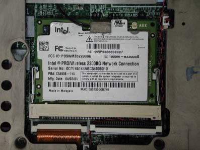
Click to zoom
Application Details
- Equipment Class
- DTS - Digital Transmission System
- Date of Grant
- Jul 04, 2004
- Application Purpose
- Original Equipment
- Date of Application
- Jul 04, 2004
- Equipment Note
- Notebook P. C.
- Frequency Range
- 2412.00000000 - 2462.00000000
- Company
- ASUSTeK Computer Inc
- Country
- Taiwan
Documents & Files
Document Text
Text extracted from the exhibit documents filed with the FCC. Open a document above to read the original.
Users Manual
Intel(R) PRO/Wireless 2200BG User's Guide Your Intel(R) PRO/Wireless 2200BG Network Connection adapter works with either 802.11b or 802.11g wireless standard. Operating at 2.4 GHz frequency at speeds of up to 54 Mbps you can now connect your computer to high-capacity existing 802.11b networks using multiple access points within large or small environments, and also to high-speed 802.11g networks. Your wireless adapter maintains automatic data rate control according to access point location to achieve the fastest possible connection. All your wireless client connections can be easily managed by the Intel(R) PROSet for Wireless utility. Using the PROSet Profile Wizard, you can create profiles automatically to suite your specific connection requirements. Enhanced security measures using 802.1x, WPA encryption and authentication, and 128-bit WEP encryption is standard for both 802.11b and 802.11g. Introduction to Wireless Networking Software Installation Using Intel(R) PROSet Connecting to a Network Security Overview Setting Up Security Troubleshooting Specifications Glossary Customer Support Safety and Regulatory Notices Warranty Adapter Registration Information in this document is subject to change without notice. (c) 2000–2003 Intel Corporation. All rights reserved. Intel Corporation, 5200 N.E. Elam Young Parkway, Hillsboro, OR 97124-6497 USA The copying or reproducing of any material in this document in any manner whatsoever without the written permission of Intel Corporation is strictly forbidden. Intel(R) is a trademark or registered trademark of Intel Corporation or its subsidiaries in the United States and other countries. Other trademarks and trade names may be used in this document to refer to either the entities claiming the marks and names or their products. Intel disclaims any proprietary interest in trademarks and trade names other than its own. Microsoft and Windows are registered trademarks of Microsoft Corporation. *Other names and brands may be claimed as the property of others. Intel Corporation assumes no responsibility for errors or omissions in this document. Nor does Intel make any commitment to update the information contained herein. September 2003 Back to Contents Page Wireless LAN Overview: Intel(R) PRO/Wireless 2200BG User's Guide About Wireless LAN Technology l Choosing a WLAN l Configuring a WLAN l Identifying a WLAN l Surveying the Site of Your WLAN l Factors Affecting Range A wireless network connects computers without using network cables. Computers use radio communications to send data between each other. You can communicate directly with other wireless computers, or connect to an existing network through a wireless access point. When you set up your wireless adapter, you select the operating mode for the kind of wireless network you want. You can use your wireless adapter to connect to other similar wireless devices that comply with the 802.11 standard for wireless networking. Choosing a Wireless LAN Wireless LANs can operate with or without access points, depending on the number of users in the network. Infrastructure mode uses access points to allow wireless computers to send and receive information. Wireless computers transmit to the access point, the access point receives the information and rebroadcasts it to other computers. The access point can also connect to a wired network or to the Internet. Multiple access points can work together to provide coverage over a wide area. Peer-to-Peer mode, also called Ad Hoc mode, works without access points and allows wireless computers to send information directly to other wireless computers. Ad Hoc Mode is only supported in 802.11b and 802.11g networks. You can use Peer-to-Peer mode to network computers in a home or small office or to set up a temporary wireless network for a meeting. Configuring a Wireless LAN There are three basic components that must be configured for an 802.11 wireless LAN to operate properly: l Network Name: Each wireless network uses a unique Network Name to identify the network. This name is called the Service Set Identifier (SSID). When you set up your wireless adapter, you specify the SSID. If you want to connect to an existing network, you must use the name for that network. If you are setting up your own network you can make up your own name and use it on each computer. The name can be up to 32 characters long and contain letters and numbers. l Profiles: When you set up your computer to access a wireless network, the wireless client manager creates a profile for the wireless settings that you specify. If you want to connect to another network, you can scan for existing networks and make a temporary connection, or create a new profile for that network. After you create profiles, your computer will automatically connect when you change locations. l Security: The 802.11 wireless networks use encryption to help protect your data. Wired equivalent privacy (WEP) uses a 64-bit or 128-bit shared encryption key to scramble data. Before a computer transmits data, it scrambles the data using the secret encryption key. The receiving computer uses this same key to unscramble the data. If you are connecting to an existing network, use the encryption key provided by the administrator of the wireless network. If you are setting up your own network you can make up your own key and use it on each computer. m Wi-Fi Protected Access (WPA) is a security enhancement that strongly increases the level of data protection and access control to a WLAN. WPA mode enforces 802.1x authentication and key-exchange to strengthen data encryption. WPA utilizes its Temporal Key Integrity Protocol (TKIP). TKIP provides important data encryption enhancements that include a per-packet key mixing function, a message integrity check (MIC) named "Michael", an extended initialization vector (IV) with sequencing rules, and a also re-keying mechanism. Using these improvement enhancements, TKIP protects against WEP's known weaknes…
Text truncated - open the document above for the full version.
Attestation Statements
ASUSTek COMPUTER INC. FCC ID.: MSQM2WM3B2200 4FL., No. 150, Li-Te Rd., Peitou, Taipei, Taiwan, R.O.C. Tel: +886 2 2894-3447 Federal Communications Commission Jun. 29, 2004 Authorization and Evaluation Division ATTESTATION FCC ID: MSQM2WM3B2200 Product: Notebook P.C. Model : M2000 We don't provide any controls or software to allow operation outside the USA frequency band when we sell this product in USA. Sincerely, ----------------------------------------- Porch Lin / Product Manager ASUSTeK COMPUTER INC.
Block Diagram
Intel / WM3B2200BG Block Diagrams Option1 miniPCI Ramon2 Radio Transceiver Ardon 2 MAC AND ANALOG PHY Differential I and Q RF PA P2023 BAND PASS FILTER T/R-DIVERSITY RF SWITCH BANDPASS FILTER BAND PASS FILTER BALUN BALUN EEPROM Rx Tx 1.2V2.8V3.3V 2.9V MainAux 40 MHz Xtal 40MHz Clock 1.8V 2.8V3.3V LNA VCO 2.9V 2.8V Option2 mPCI Connector Page 4 Ardon 2 MAC & Analog PHY Page 5,6 & 7 Voltage Regulators & DC/ DC Converter Page 3 Ramon 2 Radio Transceiver Page 8 T/R- Diversity Switch Page 11 Main Aux Antenna Ports Tx RF Rx RF Tx BB Rx BB Transceiver Control Front End Control Front End Bias Transceiver Bias MAC Bias Bias Interface EEPROM Page 5 Tx PA Page 9 Rx LNA Page 10 Ext. VCO Page 13 BB Filter Loop Filter Xtal Circuit Page 12 Intel / WM3B2200BG Option 3 mPCI Connector Ardon 2 MAC & Analog PHY Voltage Regulators & DC/ DC Converter Ramon 2 Radio Transceiver RF Front End Main Aux Antenna Ports Tx RF Rx RF Tx BB Rx BB Transceiver Control Front End Control Front End Bias Transceiver Bias MAC Bias Bias Interface EEPROM
Cover Letter(s)
ASUSTek COMPUTER INC. FCC ID.: MSQM2WM3B2200 4FL., No. 150, Li-Te Rd., Peitou, Taipei, Taiwan, R.O.C. Tel: +886 2 2894-3447 ASUSTeK COMPUTER INC. 4FL., No. 150, Li-Te Rd., Peitou, Taipei, Taiwan, R.O.C. Tel: +886 2 2894 3447 Fax:+886 2 2890 7965 Federal Communications Commission Jun. 29, 2004 Authorization and Evaluation Division Confidentiality Request Pursuant to Sections 0.457 and 0.459 of the Commission’s Rules, the Applicant Hereby requests confidential treatment of information accompanying this Application As outlined below: Schematics The above materials contain trade secrets and proprietary information not customarily Released to the public. The public disclosure of these matters might be harmful to the Applicant and provide unjustified benefits to its competitors. The Applicant understands that pursuant to Rule 0.457, disclosure of this Application and all accompanying documentation will not be made before the date of the Grant for this application. Sincerely, ----------------------------------------- Porch Lin / Product Manager ASUSTeK COMPUTER INC.
External Photos
Report No.: 046L062FI Page : 1 of 7 Version:1.0 Attachment 2 : EUT Detailed Photographs (1) EUT Photo (2) EUT Photo Report No.: 046L062FI Page : 2 of 7 Version:1.0 (3) EUT Photo (4) EUT Photo
ID Label/Location Info
ASUSTek COMPUTER INC. FCC ID.: MSQM2WM3B2200 4FL., No. 150, Li-Te Rd., Peitou, Taipei, Taiwan, R.O.C. Tel: +886 2 2894-3447 FCC ID AND DoC Label The FCC ID and DoC Label will be placed on the equipment as shown in the photograph below. Notebook P.C. ATIO Model No.: M2000 TESTED TO COMPLY WITH FCC STANDARDS FOR HOME OR OFFICE USE S/N: Made in Taiwan Notebook P.C. Model No.: M2000 F F C C C C I I D D : : M M S S Q Q M M 2 2 W W M M 3 3 B B 2 2 2 2 0 0 0 0 This device complies with Part 15 of the FCC Rules. Operation is subject to the following two conditions: (1) this device may not cause harmful interference and (2) this device must accept any interference received, including interference that may cause undesired operation. S/N: Made in Taiwan
ID Label/Location Info
ASUSTek COMPUTER INC. FCC ID.: MSQM2WM3B2200 4FL., No. 150, Li-Te Rd., Peitou, Taipei, Taiwan, R.O.C. Tel: +886 2 2894-3447 FCC ID AND DoC Label The FCC ID and DoC Label will be placed on the equipment as shown in the photograph below. Notebook P.C. ATIO Model No.: M2000 TESTED TO COMPLY WITH FCC STANDARDS FOR HOME OR OFFICE USE S/N: Made in Taiwan Notebook P.C. Model No.: M2000 F F C C C C I I D D : : M M S S Q Q M M 2 2 W W M M 3 3 B B 2 2 2 2 0 0 0 0 This device complies with Part 15 of the FCC Rules. Operation is subject to the following two conditions: (1) this device may not cause harmful interference and (2) this device must accept any interference received, including interference that may cause undesired operation. S/N: Made in Taiwan
Internal Photos
Report No.: 046L062FI Page : 2 of 7 Version:1.0 (3) EUT Photo (4) EUT Photo Report No.: 046L062FI Page : 3 of 7 Version:1.0 (5) EUT Photo (6) EUT Photo Report No.: 046L062FI Page : 4 of 7 Version:1.0 (7) EUT Photo (8) EUT Photo Report No.: 046L062FI Page : 5 of 7 Version:1.0 (9) EUT Photo (10) EUT Photo Report No.: 046L062FI Page : 6 of 7 Version:1.0 (11) EUT Photo (12) EUT Photo Report No.: 046L062FI Page : 7 of 7 Version:1.0 (13) EUT Photo
Operational Description
Report No. 046L062FI Page: 5 of 64 Version:1.0 1.2. Operational Description EUT is a Notebook P.C. with 11 channels. This device provided four kinds of transmitting speed 1, 2, 5.5 and 11Mbps. The device of RF carrier is DQPSK, DB PSK and CCK (IEEE 802.11b) or eight kinds of transmitting speed 6, 9, 12, 18, 24, 36, 48 and 54Mbps. The device of RF carrier is OFDM (IEEE 802.11g). The device adapts direct sequence spread spectrum modulation. The antenna was Connector provides diversity function to improve the receiving function. This Notebook P.C., compliant with IEEE 802.11b and IEEE 802.11g, is a high-efficiency Wireless LAN adapter. It allows your computer to connect to a wireless network and to share resources, such as files or printers without being bound to the network wires. Operation in 2.4GHz Direst Sequence Spread Spectrum (DSSS) radio transmission, the Notebook P.C. Wired Equivalent Protection (WEP) algorithm is used. In addition, its standard compliance ensures that it can communicate with any IEEE 802.11b and IEEE 802.11g network. Test Mode: Mode 1: Transmitter 802.11b Mode 1: Transmitter 802.11g
RF Exposure Info
Report No. : ES/2004/60004 Page : 1 of 48 TEST REPORT Equipment Under Test : Notebook P.C. Model No. : M2000 FCC ID : MSQM2WM3B2200 Applicant : ASUSTeK COMPUTER INC. Address of Applicant : 4FL., No. 150, Li-Te Rd., Peitou, Taipei, Taiwan, R.O.C. Date of Receipt : 2004.06.17 Date of Test(s) : 2004.06.23-2004.06.24 Date of Issue : 2004.06.28 Standards: FCC OET Bulletin 65 supplement C, ANSI/IEEE C95.1 , C95.3 In the configuration tested, the EUT complied with the standards specified above. Remarks: This report details the results of the testing carried out on one sample, the results contained in this test report do not relate to other samples of the same product. The manufacturer should ensure that all products in series production are in conformity with the product sample detailed in this report. This report may only be reproduced and distributed in full. If the product in this report is used in any configuration other than that detailed in the report, the manufacturer must ensure the new system complies with all relevant standards. Any mention of SGS Taiwan E&E Services or testing done by SGS Taiwan E&E Services in connection with distribution or use of the product described in this report must be approved by SGS Taiwan E&E Services in writing. Tested by : Dikin Yang Date : 2004/06/28 Approved by : Robert Chang Date : 2004/06/28 Report No. : ES/2004/60004 Page : 2 of 48 Contents 1. General Information 1.1 Testing Laboratory 4 1.2 Details of Applicant 4 1.3 Description of EUT(s) 4 1.4 Test Environment 5 1.5 Operation description 5 1.6 Evaluation procedures 6 1.7 The SAR Measurement System 7 1.8 System Components 9 1.9 SAR System Verification 10 1.10 Tissue Simulant Fluid for the Frequency Band 2.4 to 2.5 GHz 11 1.11 Test Standards and Limits 12 2. Instruments List 14 3. Summary of Results 15 4. Measurements 17 802.11b Configuration 1 4.1.1 Rear Side position, lowest channel 17 4.1.2 Rear Side position, middle channel 18 4.1.3 Rear Side position, highest channel 19 Configuration 2 4.1.4 Bottom face position, lowest channel 20 4.1.5 Bottom face position, middle channel 21 4.1.6 Bottom face position, highest channel 22 Configuration 3 4.1.7 LCD panel position, lowest channel 23 4.1.8 LCD panel position, middle channel 24 4.1.9 LCD panel position, highest channel 25 802.11g Configuration 1 4.2.1 Rear Side position, lowest channel 26 4.2.2 Rear Side position, middle channel 27 4.2.3 Rear Side position, highest channel 28 Configuration 2 4.2.4 Bottom face position, lowest channel 29 4.2.5 Bottom face position, middle channel 30 4.2.6 Bottom face position, highest channel 31 Configuration 3 4.2.7 LCD panel position, lowest channel 32 4.2.8 LCD panel position, middle channel 33 4.2.9 LCD panel position, highest channel 34 4.3 System Performance Validation 35 Report No. : ES/2004/60004 Page : 3 of 48 APPENDIX 1. Photographs of Test Setup 36 2. Photographs of EUT 40 3. Probe Calibration certificate 42 4. Uncertainty Analysis 46 5. Phantom description 47 6. System Validation from Original equipment supplier 48 Report No. : ES/2004/60004 Page : 4 of 48 1. General Information 1.1 Testing Laboratory SGS Taiwan Ltd. 1F, No. 134, Wukung Road, Wuku industrial zone Taipei county , Taiwan , R.O.C. Telephone : +886-2-2299-3279 Fax : +886-2-2298-0488 Internet : http://www.sgs.com.tw 1.2 Details of Applicant Name : ASUSTeK COMPUTER INC. Address : 4FL., No. 150, Li-Te Rd., Peitou, Taipei, Taiwan, R.O.C. 1.3 Description of EUT(s) Equipment Type Notebook P.C. Test Procedure FCC OET Bulletin 65, Supplement C TX Frequency range 2412-2462 MHz FCC ID MSQM2WM3B2200 Model No. M2000 Number Of Channel 11 Modulation Direct Sequence Spread Spectrum (DSSS) DEVICE CATEGORY PORTABLE DEVICES EXPOSURE CATEGORY GENERAL POPULATION / UNCONTROLLED EXPOSURE 802.11b11 Mbps Transfer Rate 802.11g6 Mbps 802.11b0.437 W/kg Max. SAR(1g) Measured 802.11g0.522 W/kg Antenna Type Internal I/O Port Mini PCI Report No. : ES/2004/60004 Page : 5 of 48 Power Supply 19Vdc from AC adapter NOTE: 1. The mini PCI card, which brand is Intel and the model name is WM3B2200BG, is specified to this EUT. 2. The EUT is powered by the following adapter: Brand DELTA Model ADP-65DB Input 100-240Vac 1.5A 50-60Hz Output 19Vdc 3.42A 3. For more detailed features description, please refer to the manufacturer's specifications or User's Manual. 1.4 Test Environment Ambient temperature : 22.2° C Tissue Simulating Liquid : 21.4° C Relative Humidity : 55 % 1.5 Operation Configuration 802.11b 802.11g Channel Frequency Under Test And Its Conducted Output Power.(Peak) 17.20dBm (2412MHz) 15.73dBm (2437MHz) 14.19dBm (2462MHz) 16.44dBm (2412MHz) 15.14dBm (2437MHz) 13.92dBm (2462MHz) Antenna Configuration Internal Antenna Antenna Position The Antenna is located at the LCD panel; and near the keyboard.(Fig 9) EUT Power Source From The Host Equipment HOST Power Source Fully Charged Battery The following test configurations have been applied in this test report: Configuration 1: Rear Side of the EUT is paralleled with flat phantom, Spacing between EUT and phantom - In contact (0 cm). (Fig.2 & Fig.3) Configuration 2: Bottom face of the EUT is paralleled with flat phantom. Spacing between EUT and phantom - In contact (0 cm) . (Fig.4 & Fig.5) Configuration 3: The LCD panel of EUT contact to the flat phantom. The transmitted antenna of the EUT located under the reference point of the flat Report No. : ES/2004/60004 Page : 6 of 48 phantom, Spacing between EUT and phantom - In contact (0 cm) (Fig.6 & Fig.7) NOTE: 1. Please reference “APPENDIX 1” for the photos of test configuration. 2. All test Configuration have been complied with the body worn configuration. 3. The Notebook has been installed the controlling software that could control the EUT transmitted channel and power. But that software is just for test software, not for normal user. 1.6 EVALUATION PROCEDURES The entire evaluation of the spatial peak values is performed within the Post-processing engine (SEMCAD). The system always…
Text truncated - open the document above for the full version.
Test Report
Report No. 046L062FI Page: 1 of 64 Version:1.0 Test Report Product Name : Notebook P.C. Model No. : M2000 FCC ID : MSQM2WM3B2200 Applicant : ASUSTeK COMPUTER INC. Address : 4FL., No. 150, Li-Te Rd., Peitou, Taipei, Taiwan, R.O.C. Date of Receipt : Jun. 07, 2004 Date of Test : Jun. 11, 2004 Report No. : 046L062FI The test results relate only to the samples tested. The test report shall not be reproduced except in full without the written approval of QuieTek Corporation. This report must not be used to claim product endorsement by NVLAP any agency of the U.S. Government Report No. 046L062FI Page: 2 of 64 Version:1.0 Test Report Certification Test Date: Jun. 11, 2004 Report No. : 046L062FI Test results relate only to the samples tested. The test report shall not be reproduced except in full without the written approval of QuieTek Corporation. This report must not be used to claim product endorsement by NVLAP any agency of the U.S. Government Product Name : Notebook P.C. Applicant : ASUSTeK COMPUTER INC. Address : 4FL., No. 150, Li-Te Rd., Peitou, Taipei, Taiwan, R.O.C. Manufacturer : ASUSTeK COMPUTER INC. Model No. : M2000 Rated Voltage : AC 120V/60Hz Trade Name : ASUS Measurement Standard : FCC CFR Title 47 Part 15 Subpart C: 2003 Measurement Procedure : ANSI C63.4: 2001 Test Result : Complied Documented By : ( Anita Chou ) Tested By : ( Geddy Jeng ) Approved By : ( Gene Chang ) Accredited by NIST (NVLAP) NVLAP Lab Code: 200533-0 Report No. 046L062FI Page: 3 of 64 Version:1.0 TABLE OF CONTENTS Description Page 1. GENERAL INFORMATION .....................................................................................................4 1.1. EUT Description............................................................................................................................4 1.2. Operational Description ................................................................................................................5 1.3. Tested System Datails....................................................................................................................6 1.4. Configuration of tested System .....................................................................................................6 1.5. EUT Exercise Software .................................................................................................................6 1.6. Test Facility ...................................................................................................................................7 2. Conducted Emission....................................................................................................................8 2.1. Test Equipment..............................................................................................................................8 2.2. Test Setup ......................................................................................................................................8 2.3. Limits ............................................................................................................................................8 2.4. Test Procedure ...............................................................................................................................9 2.5. Uncertainty ....................................................................................................................................9 2.6. Test Result of Conducted Emission.............................................................................................10 3. Peak Power Output ...................................................................................................................22 3.1. Test Equipment............................................................................................................................22 3.2. Test Setup ....................................................................................................................................22 3.3. Limits ..........................................................................................................................................22 3.4. Uncertainty ..................................................................................................................................22 3.5. Test Result of Peak Power Output...............................................................................................23 4. Radiated Emission .....................................................................................................................25 4.1. Test Equipment............................................................................................................................25 4.2. Test Setup ....................................................................................................................................25 4.3. Limits ..........................................................................................................................................26 4.4. Test Procedure .............................................................................................................................27 4.5. Uncertainty ..................................................................................................................................27 4.6. Test Result of Radiated Emission................................................................................................28 5. Band Edge ..................................................................................................................................40 5.1. Test Equipment............................................................................................................................40 5.2. Test Setup ....................................................................................................................................40 5.3. Limits ..............................................................................................…
Text truncated - open the document above for the full version.
Test Setup Photos
Report No.: 046L062FI Page : 1 of 3 Version:1.0 Attachment 1: EUT Test Setup Photographs Front View of Conducted Test Back View of Conducted Test Report No.: 046L062FI Page : 2 of 3 Version:1.0 Front View of Radiated Test Back View of Radiated Test Report No.: 046L062FI Page : 3 of 3 Version:1.0 Front View of Radiated Test (Horn) Back View of Radiated Test (Horn)
Contact Information
Applicant
Jackson Yen(Associate Vice President)
Test Firm
DEKRA Testing and Certification Co., Ltd.Sky Hsu
Technical Specifications
| # | Rule Parts | Frequency Range | Power Output |
|---|---|---|---|
| 1 | 15C | 2.41 GHz - 2.46 GHz | 52.00 mW |
Other Applications from ASUSTeK Computer Inc

MSQ-GC701
Aug 21, 2026Wireless Gaming Controller
Equipment Class
DSS - Part 15 Spread Spectrum TransmitterMSQMPDONGLE3
Aug 18, 2026WIRELESS DONGLE
Equipment Class
DTS - Digital Transmission System
MSQ-GC701D
Aug 13, 2026USB Wireless Dongle
Equipment Class
DSS - Part 15 Spread Spectrum TransmitterMSQ-CM3206DM4A
May 27, 2026Chromebook/Notebook PC
Equipment Class
DCD - Part 15 Low Power Transmitter Below 1705 kHz
MSQ-GST868003
Apr 03, 2026MODULE-WIRELESS CHRG
Equipment Class
DCD - Part 15 Low Power Transmitter Below 1705 kHz