MSQM3000NDual Band Wireless LAN Card
ASUSTeK Computer Inc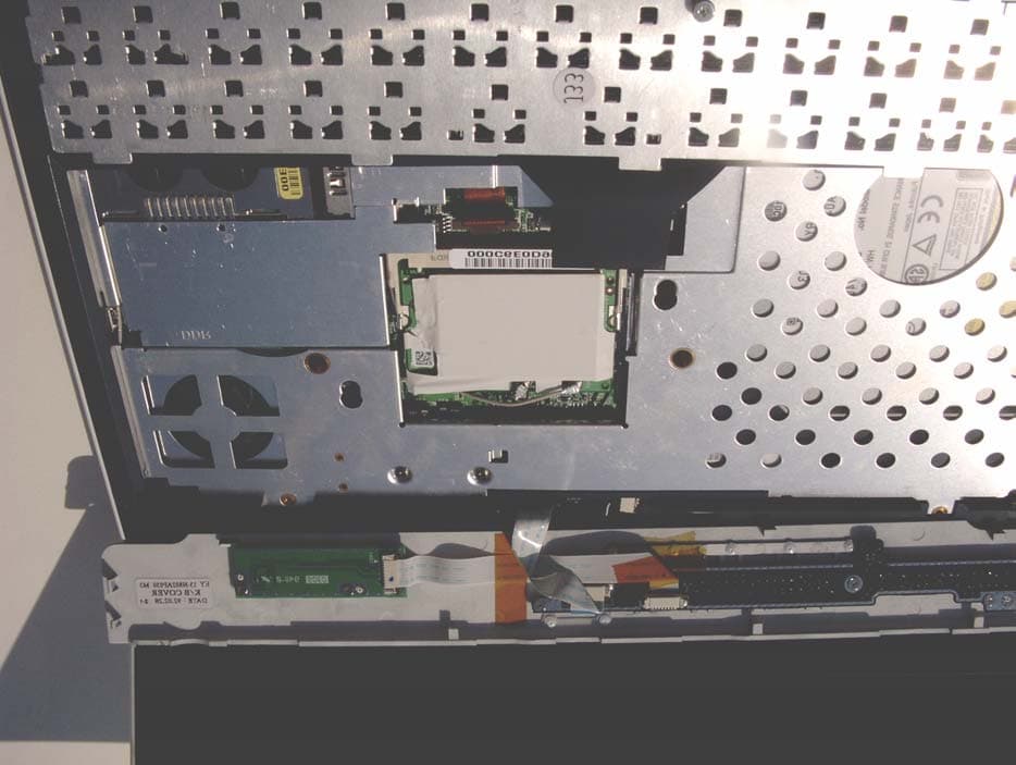
Click to zoom
Application Details
- Equipment Class
- DTS - Digital Transmission System
- Date of Grant
- Jan 13, 2004
- Application Purpose
- Original Equipment
- Date of Application
- Jul 22, 2003
- Equipment Note
- Dual Band Wireless LAN Card
- Frequency Range
- 2412.00000000 - 2462.00000000
- Company
- ASUSTeK Computer Inc
- Country
- Taiwan
Documents & Files
Document Text
Text extracted from the exhibit documents filed with the FCC. Open a document above to read the original.
Users Manual
Copyright Information No part of this manual, including the products and software described in it, may be reproduced, transmitted, tran- scribed, stored in a retrieval system, or translated into any language in any form or by any means, except documen- tation kept by the purchaser for backup purposes, without the express written permission of ASUSTeK COM- PUTER INC. (“ASUS”). ASUS PROVIDES THIS MANUAL “AS IS” WITHOUT WARRANTY OF ANY KIND, EITHER EXPRESS OR IMPLIED, INCLUDING BUT NOT LIMITED TO THE IMPLIED WARRANTIES OR CONDITIONS OF MER- CHANTABILITY OR FITNESS FOR A PARTICULAR PURPOSE. IN NO EVENT SHALL ASUS, ITS DIREC- TORS, OFFICERS, EMPLOYEES OR AGENTS BE LIABLE FOR ANY INDIRECT, SPECIAL, INCIDENTAL, OR CONSEQUENTIAL DAMAGES (INCLUDING DAMAGES FOR LOSS OF PROFITS, LOSS OF BUSI- NESS, LOSS OF USE OR DATA, INTERRUPTION OF BUSINESS AND THE LIKE), EVEN IF ASUS HAS BEEN ADVISED OF THE POSSIBILITY OF SUCH DAMAGES ARISING FROM ANY DEFECT OR ERROR IN THIS MANUAL OR PRODUCT. Product warranty or service will not be extended if: (1) the product is repaired, modified or altered, unless such repair, modification of alteration is authorized in writing by ASUS; or (2) the serial number of the product is defaced or missing. Products and corporate names appearing in this manual may or may not be registered trademarks or copyrights of their respective companies, and are used only for identification or explanation and to the owners’ benefit, without intent to infringe. SPECIFICATIONS AND INFORMATION CONTAINED IN THIS MANUAL ARE FURNISHED FOR INFOR- MATIONAL USE ONLY, AND ARE SUBJECT TO CHANGE AT ANY TIME WITHOUT NOTICE, AND SHOULD NOT BE CONSTRUED AS A COMMITMENT BY ASUS. ASUS ASSUMES NO RESPONSIBILITY OR LI- ABILITY FOR ANY ERRORS OR INACCURACIES THAT MAY APPEAR IN THIS MANUAL, INCLUDING THE PRODUCTS AND SOFTWARE DESCRIBED IN IT. Copyright © 2003 ASUSTeK COMPUTER INC. All Rights Reserved. Limitation of Liability Circumstances may arise where because of a default on ASUS’ part or other liability, you are entitled to recover damages from ASUS. In each such instance, regardless of the basis on which you are entitled to claim damages from ASUS, ASUS is liable for no more than damages for bodily injury (including death) and damage to real property and tangible personal property; or any other actual and direct damages resulted from omission or failure of performing legal duties under this Warranty Statement, up to the listed contract price of each product. ASUS will only be responsible for or indemnify you for loss, damages or claims based in contract, tort or infringe- ment under this Warranty Statement. This limit also applies to ASUS’ suppliers and its reseller. It is the maximum for which ASUS, its suppliers, and your reseller are collectively responsible. UNDER NO CIRCUMSTANCES IS ASUS LIABLE FOR ANY OF THE FOLLOWING: (1) THIRD-PARTY CLAIMS AGAINST YOU FOR DAMAGES; (2) LOSS OF, OR DAMAGE TO, YOUR RECORDS OR DATA; OR (3) SPECIAL, INCIDENTAL, OR INDIRECT DAMAGES OR FOR ANY ECONOMIC CONSEQUENTIAL DAMAGES (INCLUDING LOST PROFITS OR SAVINGS), EVEN IF ASUS, ITS SUPPLIERS OR YOUR RE- SELLER IS INFORMED OF THEIR POSSIBILITY. 1 Product Name:Notebook PC Hardware Manual Revision:2 E1279 Release Date: November 2003 Notebook PC Hardware User’s Manual Draft Version (Not for End Users) 2 Safety Statements Federal Communications Commission Statement This device complies with FCC Rules Part 15. Operation is subject to the following two conditions: • This device may not cause harmful interference, and • This device must accept any interference received, including interference that may cause undesired operation. This equipment has been tested and found to comply with the limits for a class B digital device, pursuant to Part 15 of the Federal Communications Commission (FCC) rules. These limits are designed to provide reasonable protection against harmful interference in a residential installation. This equipment generates, uses, and can radiate radio frequency energy and, if not installed and used in accordance with the instruc- tions, may cause harmful interference to radio communications. However, there is no guarantee that inter- ference will not occur in a particular installation. If this equipment does cause harmful interference to radio or television reception, which can be determined by turning the equipment off and on, the user is encouraged to try to correct the interference by one or more of the following measures: • Reorient or relocate the receiving antenna. • Increase the separation between the equipment and receiver. • Connect the equipment into an outlet on a circuit different from that to which the receiver is connected. • Consult the dealer or an experienced radio/TV technician for help. Reprinted from the Code of Federal Regulations #47, part 15.193, 1993. Washington DC: Office of the Federal Register, National Archives and Records Administration, U.S. Government Printing Office. Power Safety Requirement Products with electrical current ratings up to 6A and weighing more than 3Kg must use approved power cords greater than or equal to: H05VV-F, 3G, 0.75mm 2 or H05VV-F, 2G, 0.75mm 2 . Canadian Department of Communications Statement This digital apparatus does not exceed the Class B limits for radio noise emissions from digital apparatus set out in the Radio Interference Regulations of the Canadian Department of Communications. This Class B digital apparatus complies with Canadian ICES-003. (Cet appareil numérique de la classe B est conforme à la norme NMB-003 du Canada.) For use with AC Adaptor Model (Pour Utiliser Avec Modele): ADP-65DB (65W) WARNING! The use of a shielded-type power cord is required in order to meet FCC emission limits and to prevent interference to the nearby radio and television recep- tion. It is essential that only the supplied power cord be used. Use only shielded cables to connect I/O devices to this equipment. You are cautioned that changes or modifications not expressly approved …
Text truncated - open the document above for the full version.
Block Diagram
Ch.Center Freq Ch VCO Freq5180 36 3453.3335200 40 3466.6665220 44 34805240 48 3493.3335260 52 3506.6665280 56 35205300 60 3533.3335320 64 3546.666 Ant2Ant1 Dual-Band Diversity Switch PA LNA BPF BPF Balun Balun BPF BPF Ramon LPF BPF PA LNA Balun Filter Philips SA2400 Ardon+ 1.5 MAC BB OFDM Host Voltage Regulator EEPROM 22MHz Clock Delaware BB CCK 144 pin UBGA Ext VCO PCI Bus 33MH z Baseband Control HBus 40MHz Clock
External Photos
View of the WLAN Transmitter Location Inside the Laptop View of the WLAN Transmitter Location Inside the Laptop (Close-Up)
Internal Photos
Top View of the WLAN Transmitter “Insulation Removed” Bottom View of the WLAN Transmitter “Insulation Removed” Top View of the WLAN Transmitter “Shielding Removed”
RF Exposure Info
Page 2 of 68 ITLB-ASUS-4019 51 Spectrum WayTel. (613) 820-2730 Nepean, Ontario, K2R 1E6 Fax (613) 820 4161 e-mail: [email protected]© APREL 2002 This report shall not be reproduced, except in full, without the express written approval of APREL Laboratories Applicant:Intel Corporation Manufacturer: AsusTek Computer Inc FCC ID:MSQM3000N Equipment:Intel Mini PCI Type 3B 802.11a/b Wireless LAN Adapter model WM3B2100A inside the AsusTeck notebook Model:M3000N Serial Number:N/A Received Status:Production Unit Pre-release Standard:FCC 96-326, Guidelines for Evaluating the Environmental Effects of Radio-Frequency Radiation ENGINEERING SUMMARY This report contains the results of the engineering evaluation performed on the Intel Mini PCI Type 3B 802.11a/b Wireless LAN Adapter model WM3B2100A located inside the Asus M3000N notebook. The analysis was carried out in accordance with the requirements of FCC 96-326, “Guidelines for Evaluating the Environmental Effects of Radio-Frequency Radiation” in accordance with Supplement C and, using methodologies contained within IEEE P-1528. The Intel Mini PCI Type 3B 802.11a/b Wireless LAN Adapter model WM3B2100A located inside the Asus M3000N notebook was evaluated for compliance to the RF exposure requirements contained in section 2 “Applicable Documents”. The Intel Mini PCI Type 3B 802.11a/b Wireless LAN Adapter model WM3B2100A was operating while located inside the Asus M3000N notebook and was assessed for SAR at the maximum power level set at 16.6dBm while operating with the duty cycle set at 100%. The Intel Mini PCI Type 3B 802.11a/b Wireless LAN Adapter model WM3B2100A operates while located inside the Asus M3000N notebook and utilizes a Mini PCI type B form factor. The Intel Mini PCI Type 3B 802.11a/b Wireless LAN Adapter model WM3B2100A located inside the Asus M3000N notebook has been assessed for body, bystander, and direct contact SAR. Intel provided APREL laboratories with one pre-production model of the Asus M3000N notebook. The M3000N notebook incorporates a diverse dual band PCB antenna as supplied by YAGO (Phicomp). The Tx (main) antenna is housed internally within the laptop chassis and is located near or around the Bottom Right Hand Side of the laptop near the Palm Rest Area, below the keyboard on the main body of the laptop. Page 3 of 68 ITLB-ASUS-4019 51 Spectrum WayTel. (613) 820-2730 Nepean, Ontario, K2R 1E6 Fax (613) 820 4161 e-mail: [email protected]© APREL 2002 This report shall not be reproduced, except in full, without the express written approval of APREL Laboratories For the purpose of the SAR analysis executed and subsequent report the Intel Mini PCI Type 3B 802.11a/b Wireless LAN Adapter model WM3B2100A located inside the Asus M3000N notebook will not be labeled as the DUI (Device Under Investigation). For the purpose of this test report the DUI is the Asus notebook model number M3000N. The Intel Mini PCI Type 3B 802.11a/b Wireless LAN Adapter model WM3B2100A located inside the Asus M3000N notebook was evaluated for at the 802.11b standard for both body exposure and direct contact SAR (extremities) at low (ch#1), middle (ch#6) and high (ch#11) for the frequency range of 2412MHz to 2462MHz. Tests were executed at zero mm separation distance, for both direct contact SAR (extremities) and, body analysis. The conservative 10g average for direct contact SAR for the DUI was found to be 1.21 W/kg for the peak RF output power of the mid channel (ch#6, f=2437MHz) at the keyboard up position of DUI. For body SAR analysis the conservative 1g SAR was found to be 0.17 W/kg for the peak RF output power of the Mid channel (ch#06, f=2437MHz) at Right Hand Side position Evaluation data and graphs are presented in this report. All analysis conducted and documented in this report were performed while the Intel Mini PCI Type 3B 802.11a/b Wireless LAN Adapter model WM3B2100A was located inside the Asus notebook model M3000N. For the purpose of the SAR assessment the AC power source was used, and the conservative SAR position and frequency for each of the Test Case Scenarios was reassessed using the battery supply. It was found that the conservative SAR presented in this report was measured while using the AC supply. Based on the measured results and on how the Intel Mini PCI Type 3B 802.11a/b Wireless LAN Adapter model WM3B2100A while located inside the Asus notebook model M3000N will be marketed and used, it is certified that the DUI meets the requirements as set forth in the specifications, for the RF exposure environment contained within this report. The results presented in this report relate only to the sample evaluated. Page 4 of 68 ITLB-ASUS-4019 51 Spectrum WayTel. (613) 820-2730 Nepean, Ontario, K2R 1E6 Fax (613) 820 4161 e-mail: [email protected]© APREL 2002 This report shall not be reproduced, except in full, without the express written approval of APREL Laboratories TABLE OF CONTENTS ENGINEERING SUMMARY.................................................................................................2 1.Introduction...................................................................................................................5 2.Applicable Documents................................................................................................5 3.Test Case Scenarios..................................................................................................6 4.Test Equipment..........................................................................................................11 5.SET Up12 6.Test Results...............................................................................................................19 6.1.TRANSMITTER CHARACTERISTICS..................................................................19 6.2.SAR MEASUREMENTS..........................................................................................20 6.3.DIRECT CONTACT SAR.........................................................................................21 6.4.…
Text truncated - open the document above for the full version.
RF Exposure Info
Page 25 of 68 ITLB-ASUS-4019 51 Spectrum WayTel. (613) 820-2730 Nepean, Ontario, K2R 1E6 Fax (613) 820 4161 e-mail: [email protected]© APREL 2002 This report shall not be reproduced, except in full, without the express written approval of APREL Laboratories Appendix A TEST GRAPHIC PLOTS Page 26 of 68 ITLB-ASUS-4019 51 Spectrum WayTel. (613) 820-2730 Nepean, Ontario, K2R 1E6 Fax (613) 820 4161 e-mail: [email protected]© APREL 2002 This report shall not be reproduced, except in full, without the express written approval of APREL Laboratories GRAPH 1 Direct contact SAR (10g) Keyboard Up Distance 0 mm Mid Channel Frequency: 2437 MHz Duty Cycle 1 DateDielectric Constant ε r Conductivity σ [S/m] Probe Con/F Tissue Temp ( ºC) 10g SAR ( W/kg ) Power Drift 23/05/0350.42.036.6221.210 Page 27 of 68 ITLB-ASUS-4019 51 Spectrum WayTel. (613) 820-2730 Nepean, Ontario, K2R 1E6 Fax (613) 820 4161 e-mail: [email protected]© APREL 2002 This report shall not be reproduced, except in full, without the express written approval of APREL Laboratories SAR DATA REPORT START : 23-MAY-03 10:31:49 PM END : 23-MAY-03 10:37:27 PM CODE VERSION : 4.12 ROBOT VERSION: 4.08 PRODUCT DATA: TYPE : ASUS M3000N NOTEBOOK FREQUENCY : 2412 MHZ ANTENNA TYPE : END FED ANTENNA POSN. : INTERNAL MEASUREMENT DATA: PHANTOM NAME : ONKEYBOARD PHANTOM TYPE : UNIPHANTOM TISSUE TYPE : MUSCLE TISSUE DIELECTRIC : 50.400 TISSUE CONDUCTIVITY : 2.030 TISSUE DENSITY : 1.000 CREST FACTOR : 1.000 ROBOT NAME : CRS PROBE DATA: PROBE NAME : 163 PROBE TYPE : E FLD TRIANGLE FREQUENCY : 2450 MHZ TISSUE TYPE : MUSCLE CALIBRATED DIELECTRIC : 50.400 CALIBRATED CONDUCTIVITY : 2.030 PROBE OFFSET : 2.500 MM CONVERSION FACTOR : 6.600 DIODE COMPRESSION PT : 76.0 MV PROBE SENSITIVITY : 0.580 0.580 0.580 MV/(MW/CM^2) AMPLIFIER GAINS : 20.00 20.00 20.00 CHAN. OFFSET (MV) : -5.03 3.39 -0.64 SAMPLE: RATE: 6000 SAMPLES/SEC COUNT: 1000 SAMPLES NIDAQ GAIN: 5 SCAN TIME: 166.7 MSEC COMMENTS: KEYBOARD SIDE, OPEN, 0MM AREA SCAN - MAX LOCAL SAR VALUE AT X=27.0 Y=-16.0 = 3.00 W/KG ZOOM SCAN - MAX LOCAL SAR VALUE AT X=26.0 Y=-15.0 Z=0.0 = 8.55 W/KG MAX 1G SAR AT X=27.0 Y=-14.0 Z=0.0 = 3.68 W/KG MAX 10G SAR AT X=27.0 Y=-14.0 Z=0.0 = 1.21 W/KG Page 28 of 68 ITLB-ASUS-4019 51 Spectrum WayTel. (613) 820-2730 Nepean, Ontario, K2R 1E6 Fax (613) 820 4161 e-mail: [email protected]© APREL 2002 This report shall not be reproduced, except in full, without the express written approval of APREL Laboratories Z AXIS SCAN DIRECT CONTACT SAR 10G KEYBOARD UP Page 29 of 68 ITLB-ASUS-4019 51 Spectrum WayTel. (613) 820-2730 Nepean, Ontario, K2R 1E6 Fax (613) 820 4161 e-mail: [email protected]© APREL 2002 This report shall not be reproduced, except in full, without the express written approval of APREL Laboratories GRAPH 2 Body SAR (1g) Keyboard Closed Distance 0 mm High Channel Frequency: 2462 MHz Duty Cycle 1 DateDielectric Constant ε r Conductivity σ [S/m] Probe Con/F Tissue Temp ( ºC) 1g SAR ( W/kg ) Power Drift 23/05/0350.42.036.6220.110 Page 30 of 68 ITLB-ASUS-4019 51 Spectrum WayTel. (613) 820-2730 Nepean, Ontario, K2R 1E6 Fax (613) 820 4161 e-mail: [email protected]© APREL 2002 This report shall not be reproduced, except in full, without the express written approval of APREL Laboratories SAR DATA REPORT START : 23-MAY-03 12:42:20 AM END : 23-MAY-03 12:48:15 AM CODE VERSION : 4.12 ROBOT VERSION: 4.08 PRODUCT DATA: TYPE : ASUS M3000N NOTEBOOK FREQUENCY : 2462 MHZ TRANSMIT PWR : 0.1 W ANTENNA TYPE : END FED ANTENNA POSN. : INTERNAL MEASUREMENT DATA: PHANTOM NAME : APREL-UNI PHANTOM TYPE : UNIPHANTOM TISSUE TYPE : MUSCLE TISSUE DIELECTRIC : 50.400 TISSUE CONDUCTIVITY : 2.030 TISSUE DENSITY : 1.000 CREST FACTOR : 1.000 ROBOT NAME : CRS PROBE DATA: PROBE NAME : 163 PROBE TYPE : E FLD TRIANGLE FREQUENCY : 2450 MHZ TISSUE TYPE : MUSCLE CALIBRATED DIELECTRIC : 50.400 CALIBRATED CONDUCTIVITY : 2.030 PROBE OFFSET : 2.500 MM CONVERSION FACTOR : 6.600 DIODE COMPRESSION PT : 76.0 MV PROBE SENSITIVITY : 0.580 0.580 0.580 MV/(MW/CM^2) AMPLIFIER GAINS : 20.00 20.00 20.00 CHAN. OFFSET (MV) : -6.56 3.29 -0.86 SAMPLE: RATE: 6000 SAMPLES/SEC COUNT: 1000 SAMPLES NIDAQ GAIN: 5 SCAN TIME: 166.7 MSEC COMMENTS: FRONT SIDE, CLOSED, 0MM AREA SCAN - MAX LOCAL SAR VALUE AT X=15.0 Y=43.0 = 0.08 W/KG ZOOM SCAN - MAX LOCAL SAR VALUE AT X=16.0 Y=42.0 Z=0.0 = 0.23 W/KG MAX 1G SAR AT X=16.0 Y=43.0 Z=0.0 = 0.11 W/KG MAX 10G SAR AT X=17.0 Y=45.0 Z=0.0 = 0.05 W/KG Page 31 of 68 ITLB-ASUS-4019 51 Spectrum WayTel. (613) 820-2730 Nepean, Ontario, K2R 1E6 Fax (613) 820 4161 e-mail: [email protected]© APREL 2002 This report shall not be reproduced, except in full, without the express written approval of APREL Laboratories Z AXIS SCAN Page 32 of 68 ITLB-ASUS-4019 51 Spectrum WayTel. (613) 820-2730 Nepean, Ontario, K2R 1E6 Fax (613) 820 4161 e-mail: [email protected]© APREL 2002 This report shall not be reproduced, except in full, without the express written approval of APREL Laboratories GRAPH 3 Body SAR (1g) Keyboard Down Distance 0 mm High Channel Frequency: 2462 MHz Duty Cycle 1 DateDielectric Constant ε r Conductivity σ [S/m] Probe Con/F Tissue Temp ( ºC) 1g SAR ( W/kg ) Power Drift 23/05/0350.42.036.6220.060 Page 33 of 68 ITLB-ASUS-4019 51 Spectrum WayTel. (613) 820-2730 Nepean, Ontario, K2R 1E6 Fax (613) 820 4161 e-mail: [email protected]© APREL 2002 This report shall not be reproduced, except in full, without the express written approval of APREL Laboratories SAR DATA REPORT START : 23-MAY-03 02:54:44 AM END : 23-MAY-03 03:10:30 AM CODE VERSION : 4.12 ROBOT VERSION: 4.08 PRODUCT DATA: TYPE : ASUS M3000N NOTEBOOK FREQUENCY : 2462 MHZ TRANSMIT PWR : 0.1 W ANTENNA TYPE : END FED ANTENNA POSN. : INTERNAL MEASUREMENT DATA: PHANTOM NAME : APREL-UNI PHANTOM TYPE : UNIPHANTOM TISSUE TYPE : MUSCLE TISSUE DIELECTRIC : 50.400 TISSUE CONDUCTIVITY : 2.030 TISSUE DENSITY : 1.000 CREST FACTOR : 1.000 ROBOT NAME : CRS PROBE DATA: PROBE NAME : 163 PROBE TYPE : E FLD TRIANGLE FREQUENCY : 2450 MHZ TISSUE TYPE : MUSCLE CALIBRATED DIELECTRIC : 50.400 CALIBRATED CONDUCTIVITY : …
Text truncated - open the document above for the full version.
RF Exposure Info
NCL CALIBRATION LABORATORIES Calibration File No.: CP-310 C E R T I F I C A T E OF C A L I B R A T I O N It is certified that the equipment identified below has been calibrated in the NCL CALIBRATION LABORATORIES by qualified personnel following recognized procedures and using transfer standards traceable to NRC/NIST. Equipment: Miniature Isotropic RF Probe 2450 MHz Manufacturer: APREL Laboratories Model No.: E-010 Serial No.: 163 Calibration Procedure: SSI/DRB-TP-D01-032 Calibrated: 28 th March 2003 Released on: 28 th March 2003 Released By: ______________________________________________________ NCL CALIBRATION LABORATORIES 51 SPECTRUM WAY Division of APREL Lab. NEPEAN, ONTARIO TEL: (613) 820-4988 CANADA K2R 1E6 FAX: (613) 820-4161 NCL Calibration Laboratories Division of APREL Laboratories. Page 2 of 10 Calibrated by Approved by: Introduction This Calibration Report reproduces the results of the calibration performed in line with the SSI/DRB-TP-D01-032 E-Field Probe Calibration Procedure. The results contained within this report are for APREL E-Field Probe E-010 163. References SSI/DRB-TP-D01-032 E-Field Probe Calibration Procedure IEEE P-1528 DRAFT “Recommended Practice for Determining the Peak Spatial- Average Specific Absorption Rate (SAR) in the Human Body Due to Wireless Communications Devices: Experimental Techniques” SSI-TP-011 Tissue Calibration Procedure Conditions Probe 163 was a new probe calibration at 2450MHz. Ambient Temperature of the Laboratory: 22 ?C +/- 0.5?C Temperature of the Tissue: 21 ?C +/- 0.5?C NCL Calibration Laboratories Division of APREL Laboratories. Page 3 of 10 Calibrated by Approved by: Calibration Results Summary Probe Type: E-Field Probe E-010 Serial Number: 163 Frequency: 2450 MHz Sensor Offset: 2.38 mm Sensor Length: 2.5 mm Tip Enclosure: Glass* Tip Diameter: 7 mm Tip Length: 40 mm Total Length: 290 mm *Resistive to recommended tissue recipes per IEEE-P1528 Sensitivity in Air Channel X: 0.58 μV/(V/m) 2 Channel Y: 0.58 μV/(V/m) 2 Channel Z: 0.58 μV/(V/m) 2 Diode Compression Point: 76 mV NCL Calibration Laboratories Division of APREL Laboratories. Page 4 of 10 Calibrated by Approved by: Sensitivity in Body Tissue Frequency: 2450 MHz Epsilon: 52.7 (+/-5%) Sigma: 1.95 S/m (+/-10%) ConvF Channel X: 6.6 Channel Y: 6.6 Channel Z: 6.6 Tissue sensitivity values were calculated using a load impedance of 5 M?. Boundary Effect: Uncertainty resulting from the boundary effect is less than 2% for the distance between the tip of the probe and the tissue boundary, when less than 2.6mm. Spatial Resolution: The measured probe tip diameter is 7 mm (+/- 0.01 mm) and therefore meets the requirements of SSI/DRB-TP-D01-032 for spatial resolution. NCL Calibration Laboratories Division of APREL Laboratories. Page 5 of 10 Calibrated by Approved by: Receiving Pattern 2450 MHz (Air) Receiving Pattern Probe s/n 163 2450MHz 0 0.2 0.4 0.6 0.8 1 1.2 0 10 20 30 40 50 60 70 80 90 100 110 120 130 140 150 160 170 180 190 200 210 220 230 240 250 260 270 280 290 300 310 320 330 340 350 Ch1Ch2Ch3Tot NCL Calibration Laboratories Division of APREL Laboratories. Page 6 of 10 Calibrated by Approved by: Isotropy Error 2450 MHz (Air) Isotropy Error Probe s/n 163 2450MHz -10 -9 -8 -7 -6 -5 -4 -3 -2 -1 0 1 2 3 4 5 6 7 8 9 10 0100200300 Error [dB] Isotropy Plot Probe s/n 163 2450MHz 0 0.1 0.2 0.3 0.4 0.5 0.6 0.7 0.8 0100200300 Degrees (x10) Voltage (mV) Ch1Ch2Ch3 Isotropicity: 0.13 dB NCL Calibration Laboratories Division of APREL Laboratories. Page 7 of 10 Calibrated by Approved by: Dynamic Range Probe 163 Dynamic Range 0.01 0.1 1 10 100 1000 10000 1.0010.00100.001,000.0010,000.00100,000.001,000,000.0010,000,000.00 Electric Field [(V/m)^2] Voltage [ micro V] Uncompensated Compensated NCL Calibration Laboratories Division of APREL Laboratories. Page 8 of 10 Calibrated by Approved by: Video Bandwidth Probe Frequency Characteristics -6 -5 -4 -3 -2 -1 0 1 110100100010000 Frequency (Hz) Video Bandwidth at 500 Hz 1 dB Video Bandwidth at 1.02 KHz: 3 dB NCL Calibration Laboratories Division of APREL Laboratories. Page 9 of 10 Calibrated by Approved by: Conversion Factor Uncertainty Assessment Frequency: 2450MHz Epsilon: 52.7 (+/-5%) Sigma: 1.95 S/m (+/-10%) ConvF Channel X: 6.6 7%(K=2) Channel Y: 6.6 7%(K=2) Channel Z: 6.6 7%(K=2) To minimize the uncertainty calculation all tissue sensitivity values were calculated using a load impedance of 5 M?. Boundary Effect: For a distance of 2.6mm the evaluated uncertainty (increase in the probe sensitivity) is less than 2%. NCL Calibration Laboratories Division of APREL Laboratories. Page 10 of 10 Calibrated by Approved by: Test Equipment The test equipment used during Probe Calibration, manufacturer, model number and, current calibration status are listed and located on the main APREL server R:\NCL\Calibration Equipment\Instrument List May 2002
RF Exposure Info
January 6, 2004 Applicant: ASUSTek Computer, Inc. FCC ID: MSQM3000N Correspondence Reference Number: 25946 731 Confirmation Number: EA765565 Response to FCC comments on the above referenced Application. 1) Please clarify probe conversion factor. Probe certification does not agree with value on contour plots. Please provide new results if appropriate. Refer to “SAR Response EA765565”. 2) In conjunction with your user instruction on page 68 of 76 "Do not touch or move antenna....". Please instruct the user of the location of the antenna. Refer to page 70 in the “User’s Manual – Notebook PC (Revised)” 3) Justification for system verification. The target values appears to be developed using head liquid while retest was done in body liquid. Refer to “SAR Response EA765565”.
RF Exposure Info
51 Spectrum Way Tel (613) 820-2730 Email: [email protected] Nepean, Ontario Fax (613) 820-4161 HTTP://www.aprel.com Canada K2R 1E6 5 th January 2004 Mr. Robert Paxman Intel Corporation San Diego CA Re: FCC ID MSQM3000N Applicant: ASUSTek Computer, Inc. Correspondence Reference Number: 25946 731 Confirmation Number: EA765565 Dear Mr. Paxman, Here are the responses to the questions set by the FCC in respect to the above named project. 1) Please clarify probe conversion factor. Probe certification does not agree with value on contour plots. Please provide new results if appropriate. The probe used has two different calibration records, which depend on the amplifier being used at the probe input stage. The amplifier utilized for this assessment was a back up unit, hence the reason why the calibration report CF numbers and the CF numbers used for the assessment do not match. The correct conversion factor is indeed 6.6 as what was used during the SAR assessment. A copy of the probe calibration report has been included for reference. 2) In conjunction with your user instruction on page 68 of 76 "Do not touch or move antenna....". Please instruct the user of the location of the antenna. This has been addressed in a separate response. 3) Justification for system verification. The target values appears to be developed using head liquid while retest was done in body liquid. APREL Laboratories have run extensive experimental assessments using the IEEE dipole to assess and analyze the effects of feeding a dipole primarily matched for head applications but by illuminating a body tissue. The results from these assessments have shown that the SWR, along with RL for the dipole does not change, to a point where it would be detrimental to the efficiency, or appropriate use for the application of validating a system. Having drawn this conclusion experiments utilizing system validation methodologies were run using the dipole in both head and body tissues and the data was compared. The delta between each assessment was within 10% of the target values presented in IEEE. 51 Spectrum Way Tel (613) 820-2730 Email: [email protected] Nepean, Ontario Fax (613) 820-4161 HTTP://www.aprel.com Canada K2R 1E6 Further investigations using XFDTD have been made where both body and head tissues have been used within a high resolution mesh and compared. The results from this investigation support the findings from the experimental activities, and support the deviation which is within the 10% delta which is allowed in line with IEEE-1528. Results show that a body validation run using the dipole as described in IEEE-1528 utilizing body tissue as per the description contained within FCC supplement C is within the allowable tolerance of 10%. Taking all the results into account APREL Laboratories feel that there is no additional need to further justify using the IEEE target values. I trust that the above information should be enough for the FCC to proceed. If you have any further questions please let me know. Regards, Stuart Nicol Director Product Development, Dosimetric R&D.
Test Report
Page 1 of 15 Report Number: INTEL-030521F FCC ID: MSQM3000N Test Report And Application for Grant of Equipment Authorization Pertaining To: Equipment Under Test Model Number FCC ID: Mini PCI Type 3B Dual Band 802.11a & 802.11b WLAN Adapter WM3B2100A MSQM3000N Configuration Installed in an ASUSTek Computer, Inc. M3000N Notebook Computer MEASUREMENTS PERFORMED IN ACCORDANCE WITH Regulatory Standard(s) 47 CFR Part 15, Subpart C Section 15.247 Test Method: ANSI C63.4: 1992 American National Standard for Methods of Measurement of Radio-Noise Emissions from Low- Voltage Electrical and Electronic Equipment in the Range of 9 kHz to 40 GHz Certificate Number: 1111.01 APPLICANT: PREPARED BY: ASUSTek Computer, Inc. Aegis Labs, Inc. No. 150, Li-Te Rd. 22431 Antonio Parkway B160-417 Peitou, Taipei, Taiwan Rancho S. Margarita, CA 92688 Contact(s): Mr. Henry Yeh Agent(s): Mr. Steve Kuiper Mr. Rick Candelas Test Report #: INTEL-030521F APPENDICES REPORT BODY A TOTAL PAGES PAGES 15 30 45 Test Report Revision: None The contents of this report shall not be reproduced except in full, without the written approval of Aegis Labs, Inc. Page 2 of 15 Report Number: INTEL-030521F FCC ID: MSQM3000N TABLE OF CONTENTS SECTION TITLE PAGE COVER SHEET.................................................................................... 01 TABLE OF CONTENTS............................................................................................... 02 1.0 CERTIFICATION OF TEST DATA............................................................................. 03 2.0 SUMMARY OF TEST RESULTS.............................................................. 04 3.0 ADMINISTRATIVE DATA AND TEST DESCRIPTION.......................................... 05 4.0 DESCRIPTION OF EUT..................................................................................... 06 4.1 EUT Description..................................................................................... 06 4.1.1 Channel Number and Frequencies................................................................ 07 4.2 EUT Configuration.................................................................................. 08 4.3 List of EUT Sub-Assemblies and Host Equipment...................................................... 09 4.4 I/O Cabling Diagram and Description............................................................................. 10 5.0 TEST EQUIPMENT AND TEST SETUPS............................................................... 11 5.1 AC Power Line Conducted Emissions................................................…
Text truncated - open the document above for the full version.
Contact Information
Applicant
Jackson Yen(Associate Vice President)
Technical Contact
AmericanTCBWilliam H Graff
[email protected]703 847 4700
6731 Whittier Ave · Mclean, Virginia · United States
Test Firm
Bureau Veritas CPS (H.K.) Ltd. Taoyuan BranchRichard Chen
Technical Specifications
| # | Rule Parts | Frequency Range | Power Output |
|---|---|---|---|
| 1 | 15C | 2.41 GHz - 2.46 GHz | 48.00 mW |
Other Applications from ASUSTeK Computer Inc

MSQ-GC701
Aug 21, 2026Wireless Gaming Controller
Equipment Class
DSS - Part 15 Spread Spectrum TransmitterMSQMPDONGLE3
Aug 18, 2026WIRELESS DONGLE
Equipment Class
DTS - Digital Transmission System
MSQ-GC701D
Aug 13, 2026USB Wireless Dongle
Equipment Class
DSS - Part 15 Spread Spectrum TransmitterMSQ-CM3206DM4A
May 27, 2026Chromebook/Notebook PC
Equipment Class
DCD - Part 15 Low Power Transmitter Below 1705 kHz
MSQ-GST868003
Apr 03, 2026MODULE-WIRELESS CHRG
Equipment Class
DCD - Part 15 Low Power Transmitter Below 1705 kHz