MSQT100TARNotebook PC
ASUSTeK Computer Inc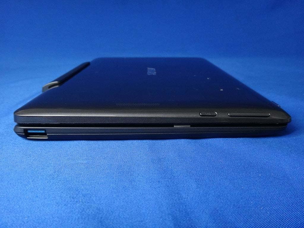
Click to zoom
Application Details
- Equipment Class
- DSS - Part 15 Spread Spectrum Transmitter
- Date of Grant
- Jul 07, 2014
- Application Purpose
- Original Equipment
- Date of Application
- Jul 07, 2014
- Equipment Note
- Notebook PC
- Frequency Range
- 2402.00000000 - 2480.00000000
- Company
- ASUSTeK Computer Inc
- Country
- Taiwan
Documents & Files
Document Text
Text extracted from the exhibit documents filed with the FCC. Open a document above to read the original.
Users Manual
15060-41300000 ASUS Mobile Dock User Guide T100 Series E9321 First Edition May 2014 2 ASUS Mobile Dock User Guide ASUS Mobile dock Connecting the ASUS Mobile Dock to your tablet allows you to use both devices as a ASUS Mobile Dock. The ASUS Mobile Dock provides additional input features to your tablet via its touchpad and keyboard functions. NOTE: The keyboard's layout may vary per region or country. Top View Release button Touchpad Keyboard Latch hookLatch hook Dock connector Hinge Left Side USB 2.0 port*/ USB 3.0 port* * on selected models only ASUS Mobile Dock User Guide 3 Using the ASUS Mobile Dock Put the ASUS Mobile Dock on a flat and stable surface. Align the ASUS Tablet with the ASUS Mobile Dock. Firmly insert the ASUS Tablet into the hinge. Ensure that the latch hooks are fully inserted to the hinge holes of your ASUS Tablet. IMPORTANT! Always pick up the entire assembly from the bottom when your ASUS Tablet is attached to the ASUS Mobile Dock. To dock your ASUS Mobile Dock 4 ASUS Mobile Dock User Guide CAUTION! • This ASUS Mobile Dock should only be used in environments with ambient temperatures between 5°C (41°F) and 35°C (95°F). • Refer to the rating label on the bottom of your ASUS Mobile Dock and ensure that your power adapter complies with this rating. • The power adapter may become warm to hot while in use. Do not cover the adapter and keep it away from your body while it is connected to a power source. IMPORTANT! • Locate the input/output rating label on your ASUS Mobile Dock and ensure that it matches the input/output rating information on your power adapter. Some ASUS Mobile Dock models may have multiple rating output currents based on the available SKU. • The power adapter varies with model type. Use only the bundled power adapter. • Power adapter information: - Input voltage: 100-240 Vac - Input frequency: 50-60 Hz - Rating output current: 2A (10W or 18 W) - Rating output voltage: 5V (10W) or 9V (18W Safety notices for your ASUS Mobile Dock Limitation of Liability Circumstances may arise where because of a default on ASUS’ part or other liability, you are entitled to recover damages from ASUS. In each such instance, regardless of the basis on which you are entitled to claim damages from ASUS, ASUS is liable for no more than damages for bodily injury (including death) and damage to real property and tangible personal property; or any other actual and direct damages resulted from omission or failure of performing legal duties under this Warranty Statement, up to the listed contract price of each product. ASUS will only be responsible for or indemnify you for loss, damages or claims based in contract, tort or infringement under this Warranty Statement. This limit also applies to ASUS’ suppliers and its reseller. It is the maximum for which ASUS, its suppliers, and your reseller are collectively responsible. UNDER NO CIRCUMSTANCES IS ASUS LIABLE FOR ANY OF THE FOLLOWING: (1) THIRD-PARTY CLAIMS AGAINST YOU FOR DAMAGES; (2) LOSS OF, OR DAMAGE TO, YOUR RECORDS OR DATA; OR (3) SPECIAL, INCIDENTAL, OR INDIRECT DAMAGES OR FOR ANY ECONOMIC CONSEQUENTIAL DAMAGES (INCLUDING LOST PROFITS OR SAVINGS), EVEN IF ASUS, ITS SUPPLIERS OR YOUR RESELLER IS INFORMED OF THEIR POSSIBILITY. Service and Support Visit our multi-language web site at http://support.asus.com ASUS Mobile Dock User Guide 5 E-Manual version Download the complete English manual version from: http://support.asus.com/download/options.aspx?SLanguage=en Copyright Information You acknowledge that all rights of this Manual remain with ASUS. Any and all rights, including without limitation, in the Manual or website, are and shall remain the exclusive property of ASUS and/or its licensors. Nothing in this Manual intends to transfer any such rights, or to vest any such rights to you. ASUS PROVIDES THIS MANUAL “AS IS” WITHOUT WARRANTY OF ANY KIND. SPECIFICATIONS AND INFORMATION CONTAINED IN THIS MANUAL ARE FURNISHED FOR INFORMATIONAL USE ONLY, AND ARE SUBJECT TO CHANGE AT ANY TIME WITHOUT NOTICE, AND SHOULD NOT BE CONSTRUED AS A COMMITMENT BY ASUS. ASUS Recycling/Takeback Services ASUS recycling and takeback programs come from our commitment to the highest standards for protecting our environment. We believe in providing solutions for you to be able to responsibly recycle our products, batteries, other components as well as the packaging materials. Please go to http://csr.asus.com/english/Takeback.htm for detailed recycling information in different regions. Coating Notice IMPORTANT! To provide electrical insulation and maintain electrical safety, a coating is applied to insulate the device except on the areas where the I/O ports are located. CE Mark Warning CE marking for devices without wireless LAN/ Bluetooth The shipped version of this device complies with the requirements of the EEC directives 2004/108/EC “Electromagnetic compatibility” and 2006/95/EC “Low voltage directive”. 6 ASUS Mobile Dock User Guide Copyright © 2014 ASUSTeK COMPUTER INC. All Rights Reserved.
Users Manual
E9349 First Edition June 2014 Notebook PC User Manual T100 Series 15060-43400000 2 Notebook PC User Manual Camera Camera indicator Touch screen panel Ambient light sensor Rear View Tablet Your Notebook PC comes with a tablet that suit your mobile needs. The tablet is also equipped with its own features for work and play which can be accessed using touch screen gestures. Top View Power button Volume button Windows® button Audio speaker Headphone output/Microphone input combo jack port Audio speaker MicroSD card slot Microphone Battery charge indicator Micro USB 2.0 port Micro HDMI port Notebook PC User Manual 3 Bottom Side Hinge hole Dock port Hinge hole Mobile dock Connecting the mobile dock to your tablet allows you to use both devices as a Notebook PC. The mobile dock provides additional input features to your tablet via its touchpad and keyboard functions. NOTE: The keyboard's layout may vary per region or country. Top View Release button Touchpad Keyboard Latch hook Latch hook Dock connector Hinge 4 Notebook PC User Manual Getting started 1. Dock the tablet to the mobile dock. Left Side USB 3.0 port 1 2 Notebook PC User Manual 5 3. Press the power button. IMPORTANT! The power adapter and its specification may vary with your package. We recommend you to use the bundled power adapter. Charge the Notebook PC for 8 hours before using it in battery mode for the first time. 2. Charge your Notebook PC. A. Connect the micro USB cable to the power adapter. B. Plug the micro USB connector into your Notebook PC. C. Plug the power adapter into a grounded power outlet. 6 Notebook PC User Manual WARNING! The bottom of the Notebook PC can get warm to hot while in use or while charging the battery pack. When working on your Notebook PC, do not place it on surfaces that can block the vents. CAUTION! • This Notebook PC should only be used in environments with ambient temperatures between 5°C (41°F) and 35°C (95°F). • Refer to the rating label on the bottom of your Notebook PC and ensure that your power adapter complies with this rating. • The power adapter may become warm to hot while in use. Do not cover the adapter and keep it away from your body while it is connected to a power source. IMPORTANT! • Ensure that your Notebook PC is connected to a grounded power adapter before turning it on for the first time. • When using your Notebook PC on power adapter mode, the socket outlet must be near to the unit and easily accessible. • Locate the input/output rating label on your Notebook PC and ensure that it matches the input/output rating information on your power adapter. Some Notebook PC models may have multiple rating output currents based on the available SKU. • The power adapter and its specification may vary with your package. We recommend you to use the bundled power adapter. • Power adapter information: - Input voltage: 100-240Vac - Input frequency: 50-60Hz - Rating output current: 2A (10W)/3A (15W) - Rating output voltage: 5V Safety notices for your Notebook PC WARNING! Read the following precautions for your Notebook PC’s battery: • Only ASUS-authorized technicians should remove the battery inside the device. • Never attempt to short-circuit your Notebook PC’s battery. • The battery used in this device may present a risk of fire or chemical burn if removed or disassembled. • Never attempt to dissamble and reassemble the battery. • Follow the warning labels for your personal safety. • Discontinue usage if leakage is found. • Risk of explosion if battery is replaced by an incorrect type. • This battery and its components must be recycled or disposed of properly. • Do not dispose of in fire.• Keep the battery and other small components away from children. Notebook PC User Manual 7 Copyright Information You acknowledge that all rights of this Manual remain with ASUS. Any and all rights, including without limitation, in the Manual or website, are and shall remain the exclusive property of ASUS and/or its licensors. Nothing in this Manual intends to transfer any such rights, or to vest any such rights to you. ASUS PROVIDES THIS MANUAL “AS IS” WITHOUT WARRANTY OF ANY KIND. SPECIFICATIONS AND INFORMATION CONTAINED IN THIS MANUAL ARE FURNISHED FOR INFORMATIONAL USE ONLY, AND ARE SUBJECT TO CHANGE AT ANY TIME WITHOUT NOTICE, AND SHOULD NOT BE CONSTRUED AS A COMMITMENT BY ASUS. Limitation of Liability Circumstances may arise where because of a default on ASUS’ part or other liability, you are entitled to recover damages from ASUS. In each such instance, regardless of the basis on which you are entitled to claim damages from ASUS, ASUS is liable for no more than damages for bodily injury (including death) and damage to real property and tangible personal property; or any other actual and direct damages resulted from omission or failure of performing legal duties under this Warranty Statement, up to the listed contract price of each product. ASUS will only be responsible for or indemnify you for loss, damages or claims based in contract, tort or infringement under this Warranty Statement. This limit also applies to ASUS’ suppliers and its reseller. It is the maximum for which ASUS, its suppliers, and your reseller are collectively responsible. UNDER NO CIRCUMSTANCES IS ASUS LIABLE FOR ANY OF THE FOLLOWING: (1) THIRD-PARTY CLAIMS AGAINST YOU FOR DAMAGES; (2) LOSS OF, OR DAMAGE TO, YOUR RECORDS OR DATA; OR (3) SPECIAL, INCIDENTAL, OR INDIRECT DAMAGES OR FOR ANY ECONOMIC CONSEQUENTIAL DAMAGES (INCLUDING LOST PROFITS OR SAVINGS), EVEN IF ASUS, ITS SUPPLIERS OR YOUR RESELLER IS INFORMED OF THEIR POSSIBILITY. Service and Support Visit our multi-language web site at http://support.asus.com E-Manual version Download the complete English manual version from: http://support.asus.com/download/options.aspx?SLanguage=en 8 Notebook PC User Manual Federal Communications Commission Statement This device complies with FCC Rules Part 15. Operation is subject to the following two conditions: • This device may not cause harmful…
Text truncated - open the document above for the full version.
External Photos
Report No:1440479R-SAUSP17V00 Page: 4 of 18 EUT Photographs Report No:1440479R-SAUSP17V00 Page: 5 of 18 Report No:1440479R-SAUSP17V00 Page: 6 of 18 Report No:1440479R-SAUSP17V00 Page: 7 of 18
ID Label/Location Info
ASUSTeK COMPUTER INC. FCC ID.: MSQT100TAR 4F, No. 150, LI-TE Rd., PEITOU, TAIPEI 112, TAIWAN Tel : 886-2-2894-3447 FCC ID Label
ID Label/Location Info
ASUSTeK COMPUTER INC. FCC ID.: MSQT100TAR 4F, No. 150, LI-TE Rd., PEITOU, TAIPEI 112, TAIWAN Tel : 886-2-2894-3447 The FCC ID Label will be placed on the equipment as shown in the photograph below.
Internal Photos
Report No:1440479R-SAUSP17V00 Page: 8 of 18 Report No:1440479R-SAUSP17V00 Page: 9 of 18 Report No:1440479R-SAUSP17V00 Page: 10 of 18 Report No:1440479R-SAUSP17V00 Page: 11 of 18 Report No:1440479R-SAUSP17V00 Page: 12 of 18 Report No:1440479R-SAUSP17V00 Page: 13 of 18 Report No:1440479R-SAUSP17V00 Page: 14 of 18 Report No:1440479R-SAUSP17V00 Page: 15 of 18 INPAQ Antenna P/N: WAG-P-LB-00-001 Report No:1440479R-SAUSP17V00 Page: 16 of 18 Report No:1440479R-SAUSP17V00 Page: 17 of 18 Report No:1440479R-SAUSP17V00 Page: 18 of 18
RF Exposure Info
Report No:1440479R-SAUSP17V00 Page: 1 of 31 FCC SAR Test Report Product Name : Notebook PC Model No. : T100T,H100T,R104T,T101T,H101T,R105T, T102T,H102T,R106T Applicant : ASUSTeK COMPUTER INC. Address : 4F, No. 150, LI-TE Rd., PEITOU, TAIPEI 112, TAIWAN Date of Receipt :2014/04/22 Issued Date :2014/05/16 Report No. :1440479R-SAUSP17V00 Report Version :V1.0 The test results relate only to the samples tested. The test results shown in the test report are traceable to the national/international standard through the calibration of the equipment and evaluated measurement uncertainty herein. This report must not be used to claim product endorsement by TAF or any agency of the government. The test report shall not be reproduced without the written approval of QuieTek Corporation. Report No:1440479R-SAUSP17V00 Page: 2 of 31 Test Report Issued Date: 2014/05/16 Report No.: 1440479R-SAUSP17V00 Product Name : Notebook PC Applicant : ASUSTeK COMPUTER INC. Address : 4F, No. 150, LI-TE Rd., PEITOU, TAIPEI 112, TAIWAN Manufacturer : 1. PEGATRON CORP TAOYUAN MFG 2. PROTEK (SHANGHAI) LTD 3.TECH-FRONT(CHONGQING)COMPUTER COLTD 4. TECH-COM(SHANGHAI) COMPUTER CO. LTD 5. DIGITEK (CHONGQING) LIMITED 6. COTEK ELECTRONICS(Suzhou)Co.,Ltd 7.Wistron InfoComm(Chongqing) Co.,Ltd Model No. : T100T,H100T,R104T,T101T,H101T,R105T, T102T,H102T,R106T Trade Name : ASUS FCC ID : MSQT100TAR Applicable Standard: FCC Oet65 Supplement C June 2001 IEEE Std. 1528-2003 47CFR § 2.1093 Measurement procedures : KDB 447498 , KDB 248227, KDB 616217,KDB 865664 Test Result : Max. SAR Measurement (1g) 802.11b/g(2.4GHz): 1.10 W/kg 802.11a(5 GHz): 1.20 W/kg Application Type : Certification Documented By : ( Adm. Specialist / Anny Chou ) Tested By : (Engineer / Wen Lee) Approved By : ( Director / Vincent Lin ) Report No:1440479R-SAUSP17V00 Page: 3 of 31 TABLE OF CONTENTS Description Page 1. General Information.............................................................................. 5 1.1 EUT Description .................................................................................................. 5 1.2 Antenna List ......................................................................................................... 5 1.3 Maximum output power and tolerance allowed for production units .................. 6 1.4 SAR Test Exclusion Calculation........................................................................... 7 1.5 Test Environment ...........................................................................................................8 2. SAR Measurement System .................................................................. 9 2.1 DASY5 System Description .......................................................................................... 9 2.1.1 Applications .............................................................................................................. 10 2.1.2 Area Scans................................................................................................................. 10 2.1.3 Zoom Scan (Cube Scan Averaging).......................................................................... 10 2.1.4 Uncertainty of Inter-/Extrapolation and Averaging .................................................. 10 2.2 DASY5 E-Field Probe ................................................................................................. 11 2.2.1 Isotropic E-Field Probe Specification ....................................................................... 11 2.3 Boundary Detection Unit and Probe Mounting Device ............................................... 12 2.4 DATA Acquisition Electronics (DAE) and Measurement Server ............................... 12 2.5 Robot ............................................................................................................................ 13 2.6 Light Beam Unit........................................................................................................... 13 2.7 Device Holder ..............................................................................................................14 2.8 SAM Twin Phantom .................................................................................................... 14 3. Tissue Simulating Liquid ................................................................... 15 3.1 The composition of the tissue simulating liquid .......................................................... 15 3.2 Tissue Calibration Result ............................................................................................. 15 3.3 Tissue Dielectric Parameters for Head and Body Phantoms ....................................... 18 4. SAR Measurement Procedure ........................................................... 19 4.1 SAR System Check ...................................................................................................... 19 4.1.1 Dipoles ...................................................................................................................... 19 4.1.2 System Check Result ................................................................................................ 19 4.2 SAR Measurement Procedure ...................................................................................... 21 5. SAR Exposure Limits ......................................................................... 22 6. Test Equipment List............................................................................ 23 7. Measurement Uncertainty .................................................................. 24 8. Conducted Power Measurement ....................................................... 25 9. Test Results......................................................................................... 27 9.1 SAR Test Results Summary ......................................................................................... 27 Report No:1440479R-SAUSP17V00 Page: 4 of 31 9.2 Simultaneous Transmission ..........................................…
Text truncated - open the document above for the full version.
Test Report
Report No.: 1440479R-RFUSP01V00 Page: 1 of 67 FCC Test Report Product Name Notebook PC Model No. T100T, H100T, R104T, T101T, H101T, R105T, T102T, H102T, R106T FCC ID. MSQT100TAR Applicant ASUSTeK COMPUTER INC. Address 4F, No. 150, LI-TE Rd., PEITOU, TAIPEI 112, TAIWAN Date of Receipt Apr. 22, 2014 Issued Date June 06, 2014 Report No. 1440479R-RFUSP01V00 Report Version V1.0 The test results relate only to the samples tested. The test results shown in the test report are traceable to the national/international standard through the calibration of the equipment and evaluated measurement uncertainty herein. This report must not be used to claim product endorsement by TAF or any agency of the government. The test report shall not be reproduced without the written approval of QuieTek Corporation. Report No.: 1440479R-RFUSP01V00 Page: 2 of 67 Test Report Issued Date: June 06, 2014 Report No.: 1440479R-RFUSP01V00 Product Name Notebook PC Applicant ASUSTeK COMPUTER INC. Address 4F, No. 150, LI-TE Rd., PEITOU, TAIPEI 112, TAIWAN Manufacturer TECH-COM(SHANGHAI) COMPUTER CO. LTD Model No. T100T, H100T, R104T, T101T, H101T, R105T, T102T, H102T, R106T FCC ID. MSQT100TAR EUT Rated Voltage AC 100-240V, 50-60Hz EUT Test Voltage AC 120V/ 60Hz Trade Name ASUS Applicable Standard FCC CFR Title 47 Part 15 Subpart C: 2012 ANSI C63.10: 2009 Test Result Complied Documented By : ( Senior Adm. Specialist / Genie Chang ) Tested By : ( Engineer / Jack Hsu ) Approved By : ( Director / Vincent Lin ) Report No.: 1440479R-RFUSP01V00 Page: 3 of 67 TABLE OF CONTENTS Description Page 1. GENERAL INFORMATION ...............................................................................................................5 1.1. EUT Description......................................................................................................................................5 1.2. Operational Description...........................................................................................................................7 1.3. Tested System Details..............................................................................................................................8 1.4. Configuration of Tested System ..............................................................................................................8 1.5. EUT Exercise Software ...........................................................................................................................8 1.6. Test Facility .............................................................................................................................................9 2. CONDUCTED EMISSION ................................................................................................................10 2.1. Test Equipment ......................................................................................................................................10 2.2. Test Setup ..............................................................................................................................................10 2.3. Limits.....................................................................................................................................................11 2.4. Test Procedure .......................................................................................................................................11 2.5. Uncertainty ............................................................................................................................................11 2.6. Test Result of Conducted Emission .......................................................................................................12 3. PEAK POWER OUTPUT ..................................................................................................................14 3.1. Test Equipment ......................................................................................................................................14 3.2. Test Setup ..............................................................................................................................................14 3.3. Limit ......................................................................................................................................................14 3.4. Test Procedure .......................................................................................................................................14 3.5. Uncertainty ............................................................................................................................................14 3.6. Test Result of Peak Power Output .........................................................................................................15 4. RADIATED EMISSION .....................................................................................................................17 4.1. Test Equipment ......................................................................................................................................17 4.2. Test Setup ..............................................................................................................................................17 4.3. Limits.....................................................................................................................................................18 4.4. Test Procedure .......................................................................................................................................19 4.5. Uncertainty ............................................................................................................................................19 4.6. Test Result of Radiated Emission ..........................................................................................................20 5. RF ANTENNA CONDUCTED TEST....................................................................................…
Text truncated - open the document above for the full version.
Test Setup Photos
Report No:1440479R-SAUSP17V00 Page: 1 of 18 Appendix C. Test Setup Photographs & EUT Photographs Test Setup Photographs EUT Top EUT Back Touch Touch Report No:1440479R-SAUSP17V00 Page: 2 of 18 EUT Right-Side EUT Bottom (NB Mode) Touch Touch Report No:1440479R-SAUSP17V00 Page: 3 of 18 Depth of the liquid in the phantom-Zoom In Note: The positions used in the measurements were according to IEEE 1528-2003.
Test Setup Photos
Report No.: 1440479R-RFUSP06V00 Page : 1 of 4 Attachment 1: EUT Test Setup Photographs Front View of Conducted Test Back View of Conducted Test Report No.: 1440479R-RFUSP06V00 Page : 2 of 4 Front View of Radiated Test Back View of Radiated Test Report No.: 1440479R-RFUSP06V00 Page : 3 of 4 Front View of Radiated Test (Horn) Back View of Radiated Test (Horn) Report No.: 1440479R-RFUSP06V00 Page : 4 of 4 Front View of Radiated Test (Horn) Back View of Radiated Test (Horn)
Contact Information
Applicant
Jackson Yen(Associate Vice President)
Technical Contact
QuieTek CorporationMaggie Chen
[email protected]886-2-8601-3788
No. 5-22, Rueishu Keng, Linkou Dist., · New Taipei City · Taiwan
Test Firm
DEKRA Testing and Certification Co., Ltd.Sky Hsu
Technical Specifications
| # | Rule Parts | Frequency Range | Power Output |
|---|---|---|---|
| 1 | 15C | 2.40 GHz - 2.48 GHz | 5.10 mW |
Other Applications from ASUSTeK Computer Inc

MSQ-GC701
Aug 21, 2026Wireless Gaming Controller
Equipment Class
DSS - Part 15 Spread Spectrum TransmitterMSQMPDONGLE3
Aug 18, 2026WIRELESS DONGLE
Equipment Class
DTS - Digital Transmission System
MSQ-GC701D
Aug 13, 2026USB Wireless Dongle
Equipment Class
DSS - Part 15 Spread Spectrum TransmitterMSQ-CM3206DM4A
May 27, 2026Chromebook/Notebook PC
Equipment Class
DCD - Part 15 Low Power Transmitter Below 1705 kHz
MSQ-GST868003
Apr 03, 2026MODULE-WIRELESS CHRG
Equipment Class
DCD - Part 15 Low Power Transmitter Below 1705 kHz