MSQT2003.5G Modular Transmitter
ASUSTeK Computer Inc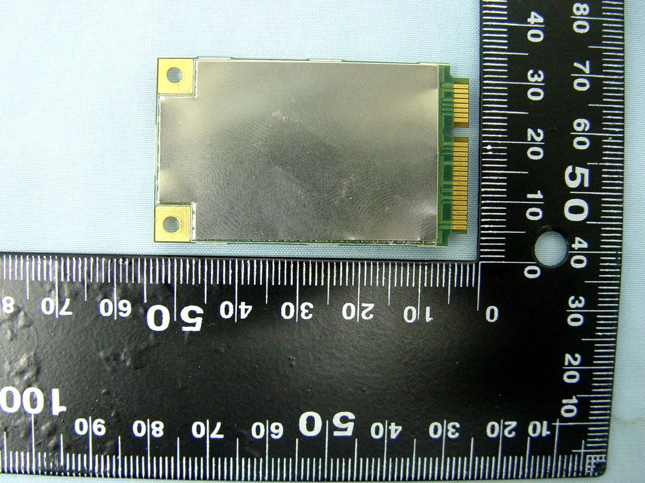
Click to zoom
Application Details
- Equipment Class
- PCB - PCS Licensed Transmitter
- Date of Grant
- Mar 25, 2008
- Application Purpose
- Original Equipment
- Date of Application
- Mar 23, 2008
- Equipment Note
- 3.5G Modular Transmitter
- Frequency Range
- 1852.40000000 - 1907.60000000
- Company
- ASUSTeK Computer Inc
- Country
- Taiwan
Documents & Files
Document Text
Text extracted from the exhibit documents filed with the FCC. Open a document above to read the original.
Users Manual
Classification Confidential Doc Number Date June 23, 2007 Version Draft v0.2 E-Tool for EMP U360 Operating Manual ASUSTeK Computer Inc. Mobile Communication Business Unit R&D Div.1 Writer:Kevin Hsu & Jim Reviser:Aden Chang E-Tool for EMP U360 ASUSTeK Strictly Confidential 1 Revision History Date Description Old Version New Version 2007/06/01 Draft created V0.1 2007/06/23 Add “Get Slot ID” and “Switch to TP Mode” Function V0.2 E-Tool for EMP U360 ASUSTeK Strictly Confidential 2 Contents 1 Introduction ................................................................................................................................. 3 2 Set Slot ID ................................................................................................................................... 3 3 Switch to TP Mode.................................................................................錯誤 錯 誤錯誤 錯誤! 尚未定義書籤 尚未定義書籤尚未定義書籤 尚未定義書籤。 。。 。 4 Operating Method ....................................................................................................................... 4 E-Tool for EMP U360 ASUSTeK Strictly Confidential 3 1 Introduction This document describes the operating method by using E-Tool for EMP U360. 2 Set Slot ID Step 1 The E-Tool V1.0 dialog box will show when you execute P_E_tool.exe. Step 2 Choose Function->Slot ID, and click it to Set Slot ID automatically. Step 3 It will show the following dialog , click “確定” to continue. E-Tool for EMP U360 ASUSTeK Strictly Confidential 4 Step 4 It will show the following dialog, turn on inactive DUT ,then click “Abort” to continue. Step 5 If it shows the following dialog , click“確定” and please repeat Step2 through to Step4 . Step 6 If the following dialog appeared , it represents Set Slot ID successfully. 4 Operating Method GSM PART Step 1 The E-Tool V1.0 dialog box will show when you execute P_E_tool.exe. E-Tool for EMP U360 ASUSTeK Strictly Confidential 5 Step 2 Choose Function->U360->GSM, and click GSM to show GSM_U360_form dialog box. Step 3 Choice com port number to communicate with Mustang. E-Tool for EMP U360 ASUSTeK Strictly Confidential 6 Step 4 Choice which tp command to send Set GSM Static TX Set GSM Switched TX E-Tool for EMP U360 ASUSTeK Strictly Confidential 7 Set GSM Static RX Set GSM Switched RX E-Tool for EMP U360 ASUSTeK Strictly Confidential 8 Reset the GSM Radio Result is showed as below E-Tool for EMP U360 ASUSTeK Strictly Confidential 9 WCDMA PART Step 1 The E-Tool V1.0 dialog box will show when you execute P_E_tool.exe. Step 2 Choose Finction->U360->WCDMA, and click WCDMA to show WCDMA_U360_form dialog box. E-Tool for EMP U360 ASUSTeK Strictly Confidential 10 Step 3 Choice com port umber to communicate with Mustang. E-Tool for EMP U360 ASUSTeK Strictly Confidential 11 Step 4 Choice Band MODE to send the tp command Set WCDMA TX E-Tool for EMP U360 ASUSTeK Strictly Confidential 12 Set WCDMA RX E-Tool for EMP U360 ASUSTeK Strictly Confidential 13 POWER Sense ADC Read Result is showed as below E-Tool for EMP U360 ASUSTeK Strictly Confidential 14 E-Tool for EMP U360 ASUSTeK Strictly Confidential 15 Step 5 Reset WCDMA Radio Compliance with FCC rules and regulation: *The maximum antenna gain allowed for use with this device is 0 dBi. E-Tool for EMP U360 ASUSTeK Strictly Confidential 16 *When the module is installed in the host device, the FCC ID label must be visible through a window on the final device or it must be visible when an access panel, door or cover is easily removed. If not, a second label must be placed on the outside of the final device that contains the following text: “Contains FCC ID: MSQT 200”. *RF Exposure Warning: In order to comply with FCC RF Exposure requirements, this device must be installed such that a minimum 20 cm separation distance is maintained between the EUT's antenna(s) and all persons during normal operation. In addition, the antenna(s) must not be co-located or operated in conjunction with any other antenna or transmitter. OEM integrators may not provide instructions to end-users pertaining to installation or removal of the EUT.
Cover Letter(s)
FederalCommunicationsCommission AuthorizationandEvaluationDivision Pursuantto Sections0.457and0.459of theCommission'sRules,weherebyrequestconfidential treatmentof informationaccompanyingthisapplicationas outlinedbelow: Schematics BlockDiagram OperationDescription PartsList TuneUpProcedure Theabovematerialscontaintradesecretsandproprietaryinformationnotcustomarilyreleasedto thepublic.Thepublicdisclosureof thesematerialsmaybe harmfulto theapplicantandprovide unjustifiedbenefitsto its competitors. Theapplicantunderstandsthatpursuantto Section0.457of theRules,disclosureof this applicationandall accompanyingdocumentationwillnotbe madebeforethedateof theGrant forthisapplication. (signature) JessLiang
Cover Letter(s)
ASUSTekCOMPUTERINC. PowerofAttorney Pleasebe notifiedthat I, JacksonYen havedesignatedJonesTsai in SportonInternationalInc. and Jess Liangin ASUSTekCOMPUTERINC.as the personsresponsiblefor this projectand to sign the form731 and otherdocumentation. Any and all acts carriedout by JonesTsai in SportonInternationalInc.,and Jess Liangin ASUSTekCOMPUTERINC.on the mattersof relatingto all processesrequiredin the FCC approvaland any communicationneededwiththe nationalauthority,shallhavethe samelegal authorityas acts on our own behalf. Thisauthorizationis limitedto the productof as following: FCCID: MSQT200 Shouldyou haveany questionsor commentsregardingthis matter,pleasehavemy best attention. (t' '/~Y)vLI--\....---..... r U acksonYen/ !\.SUSTekC~'J\1PUTERINC. Tel: 886-2-2~943447 Fax:(02)28987364 E-Mail:[email protected] r~
External Photos
FCC Test Report Report No.: FG830316 SPORTON International Inc. Page Number : A1 of A4 TEL : 886-3-327-3456 Report Issued Date : Mar. 24, 2008 FAX : 886-3-328-4978 Report Version : Rev. 01 FCC ID : MSWT200 Appendix A. External Photographs of EUT FCC Test Report Report No.: FG830316 SPORTON International Inc. Page Number : A2 of A4 TEL : 886-3-327-3456 Report Issued Date : Mar. 24, 2008 FAX : 886-3-328-4978 Report Version : Rev. 01 FCC ID : MSWT200 FCC Test Report Report No.: FG830316 SPORTON International Inc. Page Number : A3 of A4 TEL : 886-3-327-3456 Report Issued Date : Mar. 24, 2008 FAX : 886-3-328-4978 Report Version : Rev. 01 FCC ID : MSWT200 FCC Test Report Report No.: FG830316 SPORTON International Inc. Page Number : A4 of A4 TEL : 886-3-327-3456 Report Issued Date : Mar. 24, 2008 FAX : 886-3-328-4978 Report Version : Rev. 01 FCC ID : MSWT200
ID Label/Location Info
FCC Test Report Report No.: FG830316 SPORTON International Inc. Page Number : A4 of A4 TEL : 886-3-327-3456 Report Issued Date : Mar. 24, 2008 FAX : 886-3-328-4978 Report Version : Rev. 01 FCC ID : MSWT200
Internal Photos
FCC Test Report Report No.: FG830316 SPORTON International Inc. Page Number : B1 of B3 TEL : 886-3-327-3456 Report Issued Date : Mar. 24, 2008 FAX : 886-3-328-4978 Report Version : Rev. 01 FCC ID : MSQT200 Appendix B. Internal Photographs of EUT FCC Test Report Report No.: FG830316 SPORTON International Inc. Page Number : B2 of B3 TEL : 886-3-327-3456 Report Issued Date : Mar. 24, 2008 FAX : 886-3-328-4978 Report Version : Rev. 01 FCC ID : MSQT200 FCC Test Report Report No.: FG830316 SPORTON International Inc. Page Number : B3 of B3 TEL : 886-3-327-3456 Report Issued Date : Mar. 24, 2008 FAX : 886-3-328-4978 Report Version : Rev. 01 FCC ID : MSQT200 WWAN Antenna
RF Exposure Info
Document No.: 830316 RF Exposure Test Report Date:March 24, 2008 FCC ID: MSQT200 Sporton International Inc. RF Exposure Test Report for ASUS T200 Equipment : 3.5G HSDPA modem Trade Name : ASUS Model No. : T200 FCC ID : MSQT200 Filing Type : Certification Applicant : ASUSTek COMPUTER INC. 4F., No. 150, Li-Te Rd., Peitou, Taipei, Taiwan Without written approval of SPORTON International Inc., the test report shall not be reproduced except in full. SPORTON International Inc. 6F, No.106, Sec. 1, Hsin Tai Wu Rd., Hsi Chih, Taipei Hsien, Taiwan, R.O.C. Document No.: 830316 RF Exposure Test Report Date:March 24, 2008 FCC ID: MSQT200 Sporton International Inc. Maximum Permissible Exposure Test Report for T200 1.0 Introduction The report has been prepared on behalf of ASUS T200 to show compliance with the RF Exposure. 1.1 Requirements Three different categories of transmitters are defined by the FCC in OET Bulletin 65. These categories are fixed installation, mobile and portable and are defined as follows: Fixed installation: fixed location means that the device, including its antenna, is physically secured at a permanent location and is not able to be easily moved to another location. Additionally, distance to humans form the antenna is maintained to at least 2 meters. Mobile Devices: a mobile device is defined as a transmitting device designed to be used in other than fixed locations and to be generally used in such a way that a separation distance of at least 20 centimeters is normally maintained between the transmitter’s radiating structures and the body of the user or nearby persons. Transmitters designed to be used by consumers or workers that can be easily re-located are considered mobile devices if they meet the 20 centimeter separation requirement. The FCC rules for evaluating mobile devices for RF compliance are found in 47 CFR 2.1091. Portable Devices: a portable device is defined as a transmitting device designed to be used so that the radiating structure(s) of the device is/are within 20 centimeters of the body of the user. Portable device requirements are found in Section 2.1093 of the FCC’s Rules (47 CFR 2.1093) For this test report the ASUS T200 is being done as a mobile device and it can be approved by MPE calculation. The MPE is evaluated at the 20cm test distance. The use of this device is only to mobile only applications. The FCC also categorizes the use of the device as based upon the user’s awareness and ability to exercise control over his or her exposure. The two categories defined are Occupational/Controlled Document No.: 830316 RF Exposure Test Report Date:March 24, 2008 FCC ID: MSQT200 Sporton International Inc. Exposure and General Population/Uncontrolled Exposure. These two categories are defined as follows: Occupational/controlled Exposure: In general, occupational/controlled exposure limits are applicable to situation in which persons are exposed as a consequence of their employment, who have been made fully aware of the potential for exposure. Awareness of the potential for RF exposure in a workplcae or similar environment can be provided through specific training as part of a RF safety program. If appropriate, warning signs and labels can also be used to establish such awareness by providing prominent information on the risk of potential exposure and instructions on methods to minimize such exposure risks. General Population/Uncontrolled Exposure: The general population / uncontrolled exposure limits are applicable to situations in which the general public may be exposed or in which persons who are exposed as a consequence of their employment may not be made fully aware of the potential for exposure or cannot exercise control over their exposure. Members of the general public would come under this category when exposure is not employment-related; for example, in the case of a wireless transmitter that exposes persons in its vicinity. Warning labels placed on low-power consumer devices such as cellular telephones are not considered sufficient to allow the device to be considered under the occupational/controlled category, and the general population/uncontrolled exposure limits apply to these devices. Since there are no warnings or training associated with this unit and it can be used by anyone, ASUS T200 is evaluated to the General Population / Uncontrolled Exposure limits. 1.2 Radio Frequency Radiation Exposure Evaluation According to 1.1310 of the FCC rules, the power density limit for General Population/Uncontrolled Exposure is 1mW/cm 2 . As this is a mobile application, the MPE shall be calculated at 20cm to show compliance with the power density limit. The following formula was used to calculate the Power Density: S=EIRP/4πR 2 Where: S = Power Density EIRP = Effective Isotropic Radiated Power Document No.: 830316 RF Exposure Test Report Date:March 24, 2008 FCC ID: MSQT200 Sporton International Inc. R = Distance from Transmitting Antenna For this device, the calculation is as follows: Because the EUT belongs to General Population/ Uncontrolled Exposure, the limit of power density is 0.57 mW/cm 2 and 1.0 mW/cm². Band Antenna Gain (dBi) Antenna Gain (numberic) Peak output power (dBm) Peak output power (mW) Calculated RF Exposure at 20 cm (mW/cm 2 ) Limit (mW/cm 2 ) GSM850 0 1 33.5 2238.72 0.45 0.57 PCS1900 0 1 29.98 995.40 0.20 1 WCDMA Band V 0 1 23.76 237.68 0.05 0.57 WCDMA Band II 0 1 22.93 196.34 0.04 1 Based on the above calculation at 20cm, the T200 is below the Power Density limit of 0.57 mW/cm 2 and 1mW/cm 2 .
Test Report
FCC Test Report Report No. : FG830316 SPORTON International Inc. TEL : 886-3-327-3456 FAX : 886-3-328-4978 Report Version: Rev. 01 FCC Test Report According to 47 CFR Part 22H, 24E Equipment : 3.5G HSDPA modem Trade Name : ASUS Model No. : T200 FCC ID : MSQT200 Tx Frequency Range : GSM850 : 824.2 ~ 848.8MHz PCS1900 : 1850.2 ~1909.8 MHz WCDMA Band V : 826.4 ~ 846.6 MHz WCDMA Band II : 1852.4 ~1907.6 MHz Max. ERP/EIRP Power : GSM850(GSM) : 1.69 W GSM850(EDGE) : 0.68 W PCS1900(GSM) : 1.47 W PCS1900(EDGE) : 0.50 W WCDMA Band V : 0.17 W WCDMA Band II : 0.33 W Emission Designator : GSM : 300KGXW EDGE : 300KG7W WCDMA : 4M22F9W Applicant : ASUSTek COMPUTER INC. 4F., No. 150, Li-Te Rd., Peitou, Taipei, Taiwan The test result refers exclusively to the test presented test model / sample. Without written approval of SPORTON International Inc., the test report shall not be reproduced except in full. Certificate or Test Report must not be used by the applicant to claim the product in this test report endorsement by NVLAP or any agency of U.S. government. The data shown in this test report were carried out on Mar. 19, 2008 at Sporton International Inc. LAB. Report No.: FG830316, Report Version: Rev. 01. Roy Wu Manager SPORTON International Inc. No. 52, Hwa Ya 1 st Rd., Hwa Ya Technology Park, Kwei-Shan Hsiang, Tao Yuan Hsien, Taiwan, R.O.C. FCC Test Report Report No. : FG830316 SPORTON International Inc. Page Number : i TEL : 886-3-327-3456 Report Issued Date : Mar. 24, 2008 FAX : 886-3-328-4978 Report Version : Rev. 01 FCC ID : MSQT200 Table of Contents History of This Test Report .............................................................................................................................................. ii 1. General Information ....................................................................................................................................................1 1.1 Applicant............................................................................................................................................................1 1.2 Manufacturer .....................................................................................................................................................1 1.3 Feature of Equipment under Test ......................................................................................................................2 1.4 Report Date .......................................................................................................................................................2 2. Test Configuration of Equipment under Test ...........................................................................................................3 2.1 Test Manner......................................................................................................................................................3 2.2 Test Mode .........................................................................................................................................................3 2.3 Connection Diagram of Test System .................................................................................................................3 2.4 Ancillary Equipment List ....................................................................................................................................3 3. General Information of Test Site................................................................................................................................4 3.1 Test Voltage......................................................................................................................................................4 3.2 Test Compliance................................................................................................................................................4 3.3 Frequency Range..............................................................................................................................................4 3.4 Test Distance.....................................................................................................................................................4 4. Test Data and Test Result ..........................................................................................................................................5 4.1 List of Measurements and Examinations ...........................................................................................................5 4.2 RF Output Power...............................................................................................................................................6 4.3 ERP / EIRP Measurement.................................................................................................................................9 4.4 Occupied Bandwidth and Band Edge Measurement .......................................................................................14 4.5 Conducted Emission........................................................................................................................................63 4.6 Field Strength of Spurious Radiation ...............................................................................................................91 4.7 Frequency Stability (Temperature Variation) .................................................................................................104 4.8 Frequency Stability (Voltage Variation) .........................................................................................................107 5. List of Measurement Equipments..........................................................................................................................109 6. Uncertainty Evaluation ...........................................................................................................................................110 Appendix A - External Photographs of EUT Appendix B…
Text truncated - open the document above for the full version.
Contact Information
Applicant
Jackson Yen(Associate Vice President)
Technical Contact
Sporton International Inc.Daniel Lee
[email protected]886-3-327-3456
No. 52, Hwa-Ya 1st Rd., Hwa Ya Technology Park, · Tao Yuan · Taiwan
Test Firm
Sporton International IncKathy Lin
Technical Specifications
| # | Rule Parts | Frequency Range | Power Output | Emission | Tolerance |
|---|---|---|---|---|---|
| 8 | 24E | 1.85 GHz - 1.91 GHz | 190.00 mW | 4M22F9W | 0.04 ppm |
Other Applications from ASUSTeK Computer Inc

MSQ-GC701
Aug 21, 2026Wireless Gaming Controller
Equipment Class
DSS - Part 15 Spread Spectrum TransmitterMSQMPDONGLE3
Aug 18, 2026WIRELESS DONGLE
Equipment Class
DTS - Digital Transmission System
MSQ-GC701D
Aug 13, 2026USB Wireless Dongle
Equipment Class
DSS - Part 15 Spread Spectrum TransmitterMSQ-CM3206DM4A
May 27, 2026Chromebook/Notebook PC
Equipment Class
DCD - Part 15 Low Power Transmitter Below 1705 kHz
MSQ-GST868003
Apr 03, 2026MODULE-WIRELESS CHRG
Equipment Class
DCD - Part 15 Low Power Transmitter Below 1705 kHz