MSQWL127Wireless Lan Card
ASUSTeK Computer Inc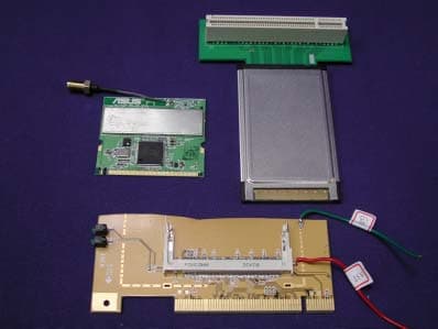
Click to zoom
Application Details
- Equipment Class
- DTS - Digital Transmission System
- Date of Grant
- Jun 12, 2003
- Application Purpose
- Original Equipment
- Date of Application
- Jun 12, 2003
- Equipment Note
- Wireless Lan Card
- Frequency Range
- 2412.00000000 - 2462.00000000
- Company
- ASUSTeK Computer Inc
- Country
- Taiwan
Documents & Files
Document Text
Text extracted from the exhibit documents filed with the FCC. Open a document above to read the original.
Users Manual
® WL-127 Wireless Fidelity Card Installation Guide First EditionJune 2003 2 ASUS WL-127 Card No part of this documentation, including the products and software described in it, may be reproduced, transmitted, transcribed , stored in a retrieval system, or translated into any language in any form or by any means, except documentation kept by thepurchaser for backup purposes, without the express written permission of ASUSTeK COMPUTER INC. ( “ ASUS ” ). ASUS PROVIDES THIS DOCUMENTATION “ AS IS ” WITHOUT WARRANTY OF ANY KIND, EITHER EXPRESS OR IMPLIED, INCLUDING BUT NOT LIMITED TO THE IMPLIED WARRANTIES OR CONDITIONS OF MERCHANTABILITY OR FITNESSFOR A PARTICULAR PURPOSE. IN NO EVENT SHALL ASUS, ITS DIRECTORS, OFFICERS, EMPLOYEES OR AGENTS BELIABLE FOR ANY INDIRECT, SPECIAL, INCIDENTAL, OR CONSEQUENTIAL DAMAGES (INCLUDING DAMAGES FORLOSS OF PROFITS, LOSS OF BUSINESS, LOSS OF USE OR DATA, INTERRUPTION OF BUSINESS AND THE LIKE), EVENIF ASUS HAS BEEN ADVISED OF THE POSSIBILITY OF SUCH DAMAGES ARISING FROM ANY DEFECT OR ERROR INTHIS DOCUMENTATION OR PRODUCT.Product warranty or service will not be extended if: (1) the product is repaired, modified or altered, unless such repair, modi fication of alteration is authorized in writing by ASUS; or (2) the serial number of the product is defaced or missing.Products and corporate names appearing in this documentation may or may not be registered trademarks or copyrights of theirrespective companies, and are used only for identification or explanation and to the owners ’ benefit, without intent to infringe. For documentation updates, visit the ASUS website at www.asus.com.tw.The specifications and information contained in this documentation are furnished for informational use only, and are subject tochange at any time without notice, and should not be construed as a commitment by ASUS. ASUS assumes no responsibility orliability for any errors or inaccuracies that may appear in this documentation, including the products and the software describ ed in it.Copyright © 2003 ASUSTeK COMPUTER INC. All Rights Reserved. ASUS WL-127 Card 3 WL-127 specifications summary* Standard IEEE 802.11b Technology Direct Sequence Spread Spectrum (DSSS) Data Transfer Rate 11Mbps (with automatic fallback to 5.5, 2 and 1Mbps) Host Interface ASUS proprietary WL-127 interface Network Types Supports Infrastructure and Ad Hoc networks Frequency Band 2.4 GHz ~ 2.5 GHz Security 64-bit/128-bit configurable WEP encryption Access Point Software access point function supports up to 31 terminals (Windows ® XP only) Operating Distance Indoors: 100 ft (30 m) @ 11Mbps Outdoors: 1000 ft (300 m) @ 11Mbps Supported OS Windows ® 98SE/ME/2000/XP Antenna Stand-alone dipole antenna *Specifications are subject to change without notice. 4 ASUS WL-127 Card 2. Package contentsCheck the following items in your ASUS WL-127 package. Contact your retailer if any item isdamaged or missing. ASUS WL-127 cardASUS WL-127 dipole antennaInstallation guideSupport CD 1. Welcome!Thank you for buying the ASUS WL-127 Card! The WL-127 card is a wireless networkinterface card for ASUS motherboards with the proprietary Wi-Fi slot. This card conforms tothe IEEE 802.11b standard for wireless local area network (WLAN) assuring you of seamlessintegration to any wireless network. The WL-127 card is sure to keep you ahead in the worldof wireless computing. ASUS WL-127 Card 5 3. Features The WL-127 card is an easy-to-use wireless solution for desktop PCs. Compliant with theIEEE 802.11b standard, the WL-127 card gives you freedom to connect to a wireless networkand the Internet without wires and cables. Employing the Direct Sequence Spread Spectrum(DSSS) technology, the WL-127 card is capable of transmitting and receiving signals throughradio waves on the 2.4 GHz band.Check out other WL-127 card advantages. • Reliable data transfer rates of up to 11Mbps with automatic fallback to 5.5, 2, and 1Mbps • Secure data transmission via Wired Equivalent Privacy (WEP) encryption • Operating distance of up to 100 ft (30 m) indoors and 1000 ft (300m) outdoors • Easy installation and full management software support • Software access point function supports up to 31 terminals (on Windows ® XP only) • Supports infrastructure (WL-127 to access point) and ad-hoc (WL-127 to another Wi-Fi device) network types • Windows ® 98SE/ME/2000/XP compatible 6 ASUS WL-127 Card 4. Card installation IMPORTANT! Before installing the WL-127 card, make sure that your system meets the following requirements. 4.1 System requirements • ASUS motherboard with Wi-Fi slot (P4C800/P4C800 Deluxe/P4P800/P4P800 Deluxe/P4P8X/P4S800/P4S800D/P4V800/P4V800D/P4R800-V/A7N8X-E)* • Intel ® Pentium ™ 4 system • Minimum 64MB system memory • Windows ® 98 SE/2000/ME/XP operating system • CD-ROM drive for software and drivers installation NOTE. Visit the ASUS website for an updated list of motherboards with WiFi slot. ASUS WL-127 Card 7 4.2 Hardware installationFollow these steps to install the WL-127 card in your system. CAUTION! Before handling the card, touch a bare metal portion of your PC to discharge static electricity from your body. Wear a wrist strap grounded to the PCchassis when handling the card.IMPORTANT! The PCI5 and the Wi-Fi slot may not be used simultaneously on certain motherboards. Check your motherboard documentation for this limitation. 1. Make sure that the PC is turned off. Unplug the power cord from the electrical socket. 2. Remove the PC cover. 3. Locate the Wi-Fi slot. Refer to your motherboard documentation for the Wi-Fi slot location. 4. Remove the rear panel bracket opposite the Wi-Fi slot. Keep the screw for later use. 5. Carefully insert the card into the Wi-Fi slot. To prevent incorrect orientation, one pin of the WL-127 connector is removed to match the covered hole on the Wi-Fi slot. 6. Secure the card with the screw that you removed earlier. 7. Replace the PC cover and plug in the power cord. 8 ASUS WL-127 Card 4.2.2 Antenna PlacementPlace the dipole a…
Text truncated - open the document above for the full version.
Cover Letter(s)
ASUSTeK COMPUTER INC. 4FL., No, 150, Li-Te Rd., Peitou, Taipei, Taiwan, R.O.C. TEL: 886-2-28943447 FAX: 886-2-28907965 Federal Communications Commission June 10, 2003 Authorization and Evaluation Division Confidentiality Request Pursuant to Sections 0.457 and 0.459 of the Commission’s Rules, the Applicant Hereby requests confidential treatment of information accompanying this Application As outlined below: Schematics The above materials contain trade secrets and proprietary information not customarily Released to the public. The public disclosure of these matters might be harmful to the Applicant and provide unjustified benefits to its competitors. The Applicant understands that pursuant to Rule 0.457, disclosure of this Application and all accompanying documentation will not be made before the date of the Grant for this application. Sincerely, ASUSTeK COMPUTER INC.
Cover Letter(s)
Federal Communications Commission 7435 Oakland Mills Road Columbia, MD 21046 Gentlemen: Regarding to the Pubic Notice DA 00-1407 pertaining to PART 15 UNLICENSED MODULAR TRANSMITTER APPROVAL, ASUSTeK COMPUTER INC.would like to request modular approval for the submission FCC ID: MSQWL127. ASUSTeK COMPUTER INC. confirms that the product complies with numbered requirements identified below: 1. The modular transmitter have its own RF shielding. 2. The modular transmitter have buffered modulation/data inputs (if such inputs are provided) to ensure that the module will comply with Part 15 requirements under conditions of excessive data rates or over-modulation. 3. The modular transmitter have its own power supply regulation. 4. The modular transmitter complies with the antenna requirements of Section 15.203 and 15.204(c). 5. The modular transmitter is tested in a stand-alone configuration. 6. The modular transmitter is labeled with its own FCC ID number 7. The modular transmitter complies with any specific rule or operating requirements applicable to the transmitter and the manufacturer must provide adequate instructions along with the module to explain any such requirements. 8. The modular transmitter complies with any applicable RF exposure requirements. Sincerely, ASUSTeK COMPUTER INC.
External Photos
Report No.: 036L303FI Page : 1 of 4 Version:1.0 Attachment 2 : EUT Detailed Photographs (1) EUT Photo (2) EUT Photo
ID Label/Location Info
ASUSTeK COMPUTER INC. 4FL., No, 150, Li-Te Rd., Peitou, Taipei, Taiwan, R.O.C. TEL: 886-2-28943447 FAX: 886-2-28907965 FCC ID: MSQWL127 FCC ID and DoC Label Wireless LAN Card Model No.: WL-127 TESTED TO COMPLY WITH FCC STANDARDS FOR HOME OR OFFICE USE S/N: Made in Taiwan Wireless LAN Card Model No.: WL-127 F F C C C C I I D D : : MSQWL127 This device complies with Part 15 of the FCC Rules. Operation is subject to the following two conditions: (1) this device may not cause harmful interference and (2) this device must accept any interference received, including interference that may cause undesired operation. S/N: Made in Taiwan The FCC ID and DoC Label will be placed on the equipment as shown in the photograph below.
ID Label/Location Info
ASUSTeK COMPUTER INC. 4FL., No, 150, Li-Te Rd., Peitou, Taipei, Taiwan, R.O.C. TEL: 886-2-28943447 FAX: 886-2-28907965 FCC ID: MSQWL127 FCC ID and DoC Label Wireless LAN Card Model No.: WL-127 TESTED TO COMPLY WITH FCC STANDARDS FOR HOME OR OFFICE USE S/N: Made in Taiwan Wireless LAN Card Model No.: WL-127 F F C C C C I I D D : : MSQWL127 This device complies with Part 15 of the FCC Rules. Operation is subject to the following two conditions: (1) this device may not cause harmful interference and (2) this device must accept any interference received, including interference that may cause undesired operation. S/N: Made in Taiwan The FCC ID and DoC Label will be placed on the equipment as shown in the photograph below.
Internal Photos
Report No.: 036L303FI Page : 2 of 4 Version:1.0 (3) EUT Photo (4) EUT Photo Report No.: 036L303FI Page : 3 of 4 Version:1.0 (5) EUT Photo (6) EUT Photo Report No.: 036L303FI Page : 4 of 4 Version:1.0 (7) EUT Photo (8) EUT Photo
Operational Description
Report No. 036L303FI Page: 6 of 46 Version:1.0 1.2. Operational Description EUT is a Wireless LAN Card with wireless LAN adapter. This device provided 11 channels and four kind of transmitting speed 1,2,5.5 and 11Mbps. The device of RF carrier is DQPSK, DB PSK and CCK. The device adapts direct sequence spread spectrum modulation. The Connector antenna was provides diversity function to improve the receiving function. This Wireless LAN Card is an IEEE 802.11b Wireless LAN adapter. It allows your computer to connect to a wireless network and to share resources, such as files or printers without being bound to the network wires. Operation in 2.4GHz Direst Sequence Spread Spectrum (DSSS) radio transmission, the Wireless LAN Card transfers data at speeds up to 64/128-bit Wired Equivalent Protection (WEP) algorithm is used. In addition, its standard compliance ensures that it can communicate with any 802.11b network.
Parts List/Tune Up Info
INPAQ 2.4Hz (80cm) INPAQ 2.4Hz (80cm) AP Antenna AP Antenna Report Apr. 10 th , 2003 Engineer Contact : Thomas Lai INPAQ Technology Co., Ltd 2F, No38, Industry Park, Hsinchu, Taiwan 300, R.O.C. TEL:+886-3-563-2828ext103 FAX:+886-3-563-6205 http://www.inpaq.com.tw e-mail:[email protected] I. Purpose of the Measurement Report A.The purpose of this measurement is used to account for the antenna performances of 2.4GHz AP antenna. These antenna performances include antenna bandwidth,VSWR ,gain, and radiation patterns. . II. Measurement Setup A. We measure the radiation pattern in the H(X-Y)E(Y-Z), shown in next page in the free space situation. B.The INPAQ’s anechoic is a far-field measurement system with the size of 8m*4m*3.5m. C. We use the Agilent 8720 ES to measure the reflection coefficient and insertion coefficient. D. The probing antenna is the TDK 900MHz~18 GHz module ( 9120D horn antenna ) , which is placed in the one side of the chamber room. And the antenna under testing (AUT) is placed in the other side of the chamber. The distance between the probing antenna and the AUT is about 4.38m. E.The gain is calibrated by the standard gain antenna (BBHA 9120LFA 700MHz~6GHZ), and we do the gain calibration every Friday for sure that the gain is under acceptable region. III. Definition E-and H-Plane X Z Y 0 o -90 o 90 o 180 o DUT H-plane Standard antenna E-Plane Z X Y DUT 0 o -90 o 90 o 180 o Standard antenna IV. Gain List for 2.4GHz AP Antenna H-plane-H: H-plane for Horizontal Polarization H-plane-V: H-plane for Vertical Polarization Total Power H: Power sum for Horizontal+ Vertical Polarization H-plane-V 2400MHz 2450MHz 2483MHz H-plane-H 2400MHz 2450MHz 2483MHz Total powerH 2400MHz 2450MHz 2483MHz E-plane-H 2400MHz 2450MHz 2483MHz E-plane-V 2400MHz 2450MHz 2483MHz Total powerE 2400MHz 2450MHz 2483MHz E-plane-H: E-plane for Horizontal Polarization E-plane-V: E-plane for Vertical Polarization Total Power E: Power sum for Horizontal+ Vertical Polarization Max (dBi) Min (dBi)Average (dBi) -15.309 -29.266 -21.07 -16.891 -28.195 -21.05 -14.541 -32.063 -19.36 Max (dBi) Min (dBi)Average (dBi) 2.122 -26.069 -1.23 1.881 -22.981 -1.92 2.39 -26.279 -1.18 Max (dBi)Min (dBi)Average (dBi) 2.16 -22.28 -1.18 1.92 -19.79 -1.87 2.45 -21.24 -1.12 Max (dBi) Min (dBi)Average (dBi) 1.974 1.2851.59 1.109 0.0880.60 2.128 0.8211.33 Max (dBi) Min (dBi)Average (dBi) -16.171 -28.043 -20.12 -16.911 -26.519 -20.81 -14.908 -31.258 -19.17 Max (dBi)Min (dBi) Average (dBi) 2.01 1.321.62 1.13 0.100.63 2.14 0.901.37 V. Antenna VSWR and Patterns frequencyVSWR 2400MHz1.353 2450MHz1.155 2483MHz1.135 H-plane Pattern (Vertical& Horizontal Polarization) H-plane Pattern (Total Power) -40 -35 -30 -25 -20 -15 -10 -5 0 5 0 30 60 90 120 150 180 210 240 270 300 330 -40 -35 -30 -25 -20 -15 -10 -5 0 5 2400MHz 2450MHz 2483MHz 2400MHz 2450MHz 2483MHz -40 -35 -30 -25 -20 -15 -10 -5 0 5 0 30 60 90 120 150 180 210 240 270 300 330 -40 -35 -30 -25 -20 -15 -10 -5 0 5 2400MHz 2450MHz 2483MHz E-plane Pattern (Vertical &Horizontal Polarization ) E-plane Pattern (Total Power) -40 -35 -30 -25 -20 -15 -10 -5 0 5 0 30 60 90 120 150 180 210 240 270 300 330 -40 -35 -30 -25 -20 -15 -10 -5 0 5 2400MHz 2450MHz 2483MHz 2400MHz 2450MHz 2483MHz -40 -35 -30 -25 -20 -15 -10 -5 0 5 0 30 60 90 120 150 180 210 240 270 300 330 -40 -35 -30 -25 -20 -15 -10 -5 0 5 2400MHz 2450MHz 2483MHz
RF Exposure Info
Report No. 036L303FI Page: 1 of 3 Version: 1.0 RF Exposure Evaluation declaration Product Name : Wireless LAN Card Model No.: WL-127 Applicant : ASUSTeK COMPUTER INC. Address : 4FL., No, 150, Li-Te Rd., Peitou, Taipei, Taiwan, R.O.C. Date of Receipt : May 27, 2003 Date of Declaration: May 27, 2003 Report No. : 036L303FI The declaration results relate only to the samples calculated. The declaration shall not be reproduced except in full without the written approval of QuieTek Corporation. Report No. 036L303FI Page: 2 of 3 Version: 1.0 1. RF Exposure Evaluation 1.1. Limits According to FCC 1.1310: The criteria listed in the following table shall be used to evaluate the environment impact of human exposure to radio frequency (RF) radiation as specified in 1.1307(b) LIMITS FOR MAXIMUM PERMISSIBLE EXPOSURE (MPE) Frequency Range (MHz) Electric Field Strength (V/m) Magnetic Field Strength (A/m) Power Density (mW/cm 2 ) Average Time (Minutes) (A) Limits for Occupational/ Control Exposures 300-1500 -- -- F/300 6 1500-100,000 -- -- 5 6 (B) Limits for General Population/ Uncontrolled Exposures 300-1500 -- -- F/1500 6 1500-100,000 -- -- 1 30 F= Frequency in MHz Friis Formula Friis transmission formula: Pd = (Pout*G)/(4*pi*r 2 ) Where Pd = power density in mW/cm 2 Pout = output power to antenna in mW G = gain of antenna in linear scale Pi = 3.1416 R = distance between observation point and center of the radiator in cm Pd id the limit of MPE, 1 mW/cm 2 . If we know the maximum gain of the antenna and the total power input to the antenna, through the calculation, we will know the distance r where the MPE limit is reached. 1.2. Test Procedure Software provided by client enabled the EUT to transmit and receive data at lowest, middle and highest channel individually. The temperature and related humidity: 18°Cand 78% RH. Report No. 036L303FI Page: 3 of 3 Version: 1.0 1.3. Test Result of RF Exposure Evaluation Product : Wireless LAN Card Test Item : RF Exposure Evaluation Test Site : No.3 OATS Test Mode : Normal Operation Antenna Gain Antenna Gain: The maximum Gain measured in fully anechoic chamber is 2.07dBi, 2.45dBi in linear scale. Output Power Into Antenna & RF Exposure Evaluation Distance (2.07dBi): Channel Frequency (MHz) Output Power to Antenna (mW) Power Density at R = 20 cm (mW/cm2) 1 2414.00 54.9541 0.0176 6 2438.90 47.3151 0.0152 11 2463.90 39.0841 0.0125 Output Power Into Antenna & RF Exposure Evaluation Distance (2.45dBi): Channel Frequency (MHz) Output Power to Antenna (mW) Power Density at R = 20 cm (mW/cm2) 1 2414.00 54.9541 0.0192 6 2438.90 47.3151 0.0165 11 2463.90 39.0841 0.0137 The distance r (4 th column) calculated from the Fries transmission formula is far shorter than 20 cm separation requirement.
Test Report
Report No. 036L303FI Page: 1 of 46 Version:1.0 Test Report Product Name : Wireless LAN Card Model No.: WL-127 FCC ID.: MSQWL127 Applicant : ASUSTeK COMPUTER INC. Address : 4FL., No, 150, Li-Te Rd., Peitou, Taipei, Taiwan, R.O.C. Date of Receipt : May 27, 2003 Date of Test : May 27, 2003 Report No. : 036L303FI The test results relate only to the samples tested. The test report shall not be reproduced except in full without the written approval of QuieTek Corporation. This report must not be used to claim product endorsement by NVLAP any agency of the U.S. Government Report No. 036L303FI Page: 2 of 46 Version:1.0 Test Report Certification Test Date : May 27, 2003 Report No. : 036L303FI Test results relate only to the samples tested. The test report shall not be reproduced except in full without the written approval of QuieTek Corporation. This report must not be used to claim product endorsement by NVLAP any agency of the U.S. Government Product Name : Wireless LAN Card Applicant : ASUSTeK COMPUTER INC. Address : 4FL., No, 150, Li-Te Rd., Peitou, Taipei, Taiwan, R.O.C. Manufacturer : ASUSTeK COMPUTER INC. Model No. : WL-127 Rated Voltage : AC 120V/60Hz Trade Name : ASUS Measurement Standard : FCC Part 15 Subpart C Paragraph 15.247 Measurement Procedure : ANSI C63.4: 1992 Test Result : Complied Documented By : ( Grace Lin ) Tested By : ( Tony Hsieh ) Approved By : ( Gene Chang ) Accredited by NIST (NVLAP) NVLAP Lab Code: 200533-0 Report No. 036L303FI Page: 3 of 46 Version:1.0 TABLE OF CONTENTS Description Page 1. GENERAL INFORMATION .....................................................................................................5 1.1. EUT Description............................................................................................................................5 1.2. Operational Description ................................................................................................................6 1.3. Tested System Datails....................................................................................................................7 1.4. Configuration of tested System .....................................................................................................8 1.5. EUT Exercise Software .................................................................................................................8 1.6. Test Facility ...................................................................................................................................9 2. Conducted Emission..................................................................................................................10 2.1. Test Equipment............................................................................................................................10 2.2. Test Setup ....................................................................................................................................10 2.3. Limits ..........................................................................................................................................10 2.4. Test Procedure .............................................................................................................................11 2.5. Test Result of Conducted Emission.............................................................................................12 3. Peak Power Output ...................................................................................................................16 3.1. Test Equipment............................................................................................................................16 3.2. Test Setup ....................................................................................................................................16 3.3. Limits ..........................................................................................................................................16 3.4. Test Result of Peak Power Output...............................................................................................17 4. Radiated Emission .....................................................................................................................18 4.1. Test Equipment............................................................................................................................18 4.2. Test Setup ....................................................................................................................................18 4.3. Limits ..........................................................................................................................................19 4.4. Test Procedure .............................................................................................................................20 4.5. Test Result of Radiated Emission................................................................................................21 5. Band Edge ..................................................................................................................................33 5.1. Test Equipment............................................................................................................................33 5.2. Test Setup ....................................................................................................................................33 5.3. Limits ..........................................................................................................................................34 5.4. Test Procedure .............................................................................................................................34 5.5. Test Result of Band Edge ............................................................................................................35 6. Occupied Bandwidth ...................................................................................................…
Text truncated - open the document above for the full version.
Test Setup Photos
Report No.: 036L303FI Page : 1 of 3 Version:1.0 Attachment 1: EUT Test Setup Photographs Front View of Conducted Test Back View of Conducted Test Report No.: 036L303FI Page : 2 of 3 Version:1.0 Front View of Radiated Test Back View of Radiated Test Report No.: 036L303FI Page : 3 of 3 Version:1.0 Front View of Radiated Test (Horn)
Contact Information
Applicant
Jackson Yen(Associate Vice President)
Test Firm
DEKRA Testing and Certification Co., Ltd.Sky Hsu
Technical Specifications
| # | Rule Parts | Frequency Range | Power Output |
|---|---|---|---|
| 1 | 15C | 2.41 GHz - 2.46 GHz | 55.00 mW |
Other Applications from ASUSTeK Computer Inc

MSQ-GC701
Aug 21, 2026Wireless Gaming Controller
Equipment Class
DSS - Part 15 Spread Spectrum TransmitterMSQMPDONGLE3
Aug 18, 2026WIRELESS DONGLE
Equipment Class
DTS - Digital Transmission System
MSQ-GC701D
Aug 13, 2026USB Wireless Dongle
Equipment Class
DSS - Part 15 Spread Spectrum TransmitterMSQ-CM3206DM4A
May 27, 2026Chromebook/Notebook PC
Equipment Class
DCD - Part 15 Low Power Transmitter Below 1705 kHz
MSQ-GST868003
Apr 03, 2026MODULE-WIRELESS CHRG
Equipment Class
DCD - Part 15 Low Power Transmitter Below 1705 kHz