MSQWL140USB WLAN SpaceLink Client
ASUSTeK Computer Inc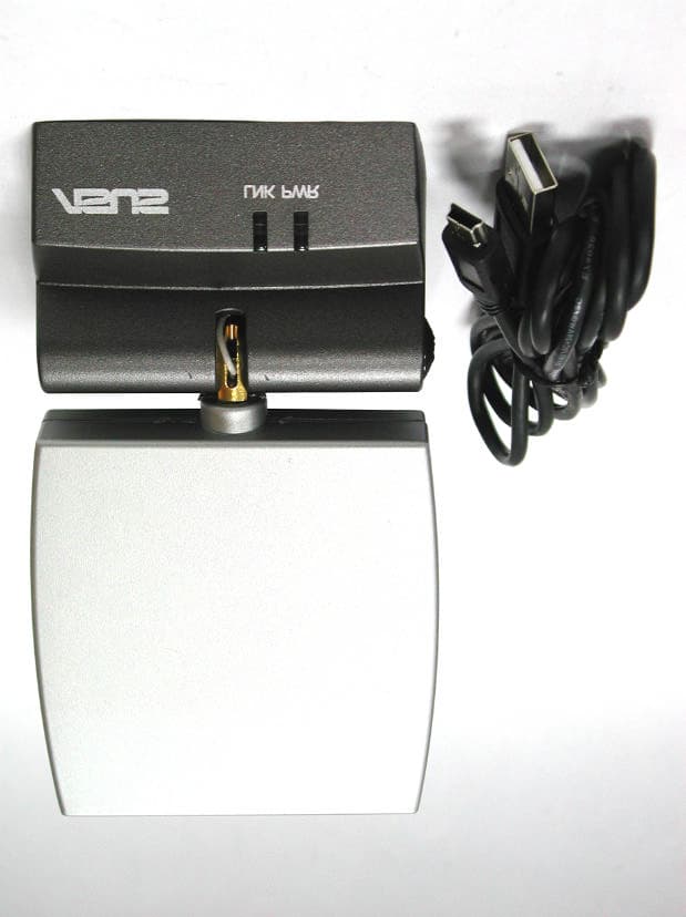
Click to zoom
Application Details
- Equipment Class
- DTS - Digital Transmission System
- Date of Grant
- Mar 03, 2003
- Application Purpose
- Original Equipment
- Date of Application
- Mar 02, 2003
- Equipment Note
- USB WLAN SpaceLink Client
- Frequency Range
- 2412.00000000 - 2462.00000000
- Company
- ASUSTeK Computer Inc
- Country
- Taiwan
Documents & Files
Document Text
Text extracted from the exhibit documents filed with the FCC. Open a document above to read the original.
Users Manual
ASUS USB SpaceLink Client WL-140 (For 802.11b Wireless Networks) User’s Manual 2ASUS USB SpaceLink Client No part of this manual, including the products and software described in it, may be reproduced, transmitted, transcribed, stored in a retrieval system, or translated into any language in any form or by any means, except docu- mentation kept by the purchaser for backup purposes, without the express written permission of ASUSTeK COMPUTER INC. (“ASUS”). ASUS PROVIDES THIS MANUAL “AS IS” WITHOUT WARRANTY OF ANY KIND, EITHER EXPRESS OR IMPLIED, INCLUDING BUT NOT LIMITED TO THE IMPLIED WARRANTIES OR CONDITIONS OF MERCHANTABILITY OR FITNESS FOR A PARTICULAR PUR- POSE. IN NO EVENT SHALL ASUS, ITS DIRECTORS, OFFICERS, EMPLOYEES OR AGENTS BE LIABLE FOR ANY INDIRECT, SPE- CIAL, INCIDENTAL, OR CONSEQUENTIAL DAMAGES (INCLUD- ING DAMAGES FOR LOSS OF PROFITS, LOSS OF BUSINESS, LOSS OF USE OR DATA, INTERRUPTION OF BUSINESS AND THE LIKE), EVEN IF ASUS HAS BEEN ADVISED OF THE POSSIBILITY OF SUCH DAMAGES ARISING FROM ANY DEFECT OR ERROR IN THIS MANUAL OR PRODUCT. Product warranty or service will not be extended if: (1) the product is re- paired, modified or altered, unless such repair, modification of alteration is authorized in writing by ASUS; or (2) the serial number of the product is defaced or missing. Products and corporate names appearing in this manual may or may not be registered trademarks or copyrights of their respective companies, and are used only for identification or explanation and to the owners’ benefit, without intent to infringe. SPECIFICATIONS AND INFORMATION CONTAINED IN THIS MANUAL ARE FURNISHED FOR INFORMATIONAL USE ONLY, AND ARE SUBJECT TO CHANGE AT ANY TIME WITHOUT NOTICE, AND SHOULD NOT BE CONSTRUED AS A COMMITMENT BY ASUS. ASUS ASSUMES NO RESPONSIBILITY OR LIABILITY FOR ANY ERRORS OR INACCURACIES THAT MAY APPEAR IN THIS MANUAL, IN- CLUDING THE PRODUCTS AND SOFTWARE DESCRIBED IN IT. Copyright © 2003 ASUSTeK COMPUTER INC. All Rights Reserved. Copyright Information Product Name:ASUS USB SpaceLink Client (WL-140) Manual Revision:1 E1219 Release Date:February 2003 ASUS USB SpaceLink Client3 Copyright Information ASUSTeK COMPUTER INC. (Asia-Pacific) Address:150 Li-Te Road, Peitou, Taipei, Taiwan 112 General Tel:+886-2-2894-3447 General Fax:+886-2-2894-3449 General Email: [email protected] Technical Support MB/Others (Tel): +886-2-2890-7121 (English) Notebook (Tel): +886-2-2890-7122 (English) Desktop/Server: +886-2-2890-7123 (English) Support Fax:+886-2-2890-7698 Support Email: [email protected] Web Site:www.asus.com.tw ASUS COMPUTER INTERNATIONAL (America) Address:44370 Nobel Drive, Fremont, CA 94538, USA General Fax:+1-510-608-4555 General Email: [email protected] Technical Support Support Fax:+1-510-608-4555 General Support: +1-502-933-8713 Web Site:www.asus.com Support Email: [email protected] ASUS COMPUTER GmbH (Germany & Austria) Address:Harkortstr. 25, 40880 Ratingen, BRD, Germany General Fax:+49-2102-442066 General Email: [email protected] (for marketing requests only) Technical Support Support Hotline: MB/Others: +49-2102-9599-0 Notebook (Tel): +49-2102-9599-10 Support Fax:+49-2102-9599-11 Support (Email): www.asuscom.de/de/support (for online support) Web Site:www.asuscom.de 4ASUS USB SpaceLink Client 1. Introduction ............................................................................. 7 1.1 Overview ...................................................................................... 7 1.2 Package Contents ........................................................................ 8 2. Installation ............................................................................... 8 2.1 Orientating the Antenna ............................................................... 8 2.2 Reading the SpaceLink LEDs ...................................................... 9 2.3 Installing the SpaceLink Driver .................................................. 10 2.4 Verifying the SpaceLink Driver ................................................... 11 2.5 Verifying the TCP/IP Protocol .................................................... 13 2.5.1 Installing the TCP/IP Protocol ......................................... 14 2.5.2 Configuring TCP/IP Properties ....................................... 15 2.5.3 Configuring Advanced TCP/IP Properties ...................... 16 2.5.4 Verifying TCP/IP Settings ............................................... 16 2.6 Installing ASUS USB SpaceLink Client Utilities ......................... 17 3. Software Reference .............................................................. 19 3.1 Overview .................................................................................... 19 3.2 Windows XP Wireless Options .................................................. 20 3.3 Control Center ............................................................................ 21 3.4 Wireless Settings ....................................................................... 23 More than one ASUS SpaceLink Card ...................................... 24 3.4.1 Status - Status Tab ......................................................... 24 3.4.2 Status - Connection Tab ................................................. 27 3.4.3 Status - IP Config Tab ..................................................... 28 3.4.4 Config - Basic Tab .......................................................... 29 3.4.5 Config - Encryption Tab .................................................. 32 3.4.6 Config - Advanced Tab ................................................... 35 3.4.7 Survey - Site Survey Tab ................................................ 37 3.4.8 About - Version Info Tab ................................................. 38 3.4.9 Link Status ...................................................................... 39 Table of Contents ASUS USB SpaceLink Client5 Table of Contents 3.5 Mobile Manager ......................................................................... 40 3.5.1 Main Window ....…
Text truncated - open the document above for the full version.
Users Manual
Prohibition of co-location This device must not be co-located or operating in conjunction with any other antenna or transmitter Information of the responsible party for WL-140 The identification of the product: Product Name : ASUS USB SpaceLink Client Model : WL-140 This device complies with Part 15 of the FCC Rules. Operation is subject to the following two conditions: (1) This device may not cause harmful interference. (2) This device must accept any interference received, including interference that may cause undesired operation. Technical Support: ASUSTeK Computer Inc. Address : 150, Li-te Rd., Peitou, Taipei, Taiwan, R.O.C. Telephone : +886-2-28943447 Fax : +886-2-28943449 Email : [email protected] Technical Support in the US: ASUS Computer International (American) Address : 44370 Nobel Drive, Fremont, CA 94538 Telephone : +1-502-9338713 Email : [email protected]
Cover Letter(s)
Training Research Co., Ltd. 255 Nanyang Street, Shijr, Taipei Hsien 221, Taiwan, R.O.C. TEL: 886-2-26935155 FAX: 886-2-26934440 Email: [email protected] TRCSince1985 ® March 3, 2003 RE : ASUSTeK Computer FCC ID : MSQWL140 Dear Timothy: After the review of your comments, we have made some response upon your advice; they are summarized as follows: 1. The label is updated per your request, please find them in the uploads. 2. The RF Exposure statements is inserted into the manual as shown in the uploads. 3. The pages of the report you have specified is updated and uploaded. 4. The RBW of our measurement is followed the FCC instruction, please find the material we have uploaded and comment if any other issue should us be noted. 5. The manual is inserted with the compliance sheet separately and please find the materials as the uploads. Should you have any questions or more information is requested, please don’t hesitate to ask us. Thank you. Sincerely yours, Eric Wong Project Engineer Training Research Co Ltd.
Cover Letter(s)
American Telecommunications Certification Body Inc. 6731 Whittier Ave, McLean, VA 22101 February 24, 2003 RE: ASUSTek Computer FCC ID: MSQWL140 After a review of the submitted information, I have a few comments on the above referenced Application. 1) The FCC ID number must be preceded by "FCC ID:". Please correct the FCC Label. 2) The RF exposure statements do not appear to be provided in the users manual. Please provide a corrected users manual that includes this information. 3) Section III of the test report states that the device contains a permanently attached antenna. Please note that the EUT shows a connector internal to the device, but is not permanently attached. Please adjust this section as necessary. 4) Note 1 on page 19/36 of the test report references a RBW of 300 kHz. This is incorrect. This should be 100 kHz. Please correct. 5) The device is also subject to a DoC authorization as shown by its label. However the information specified by 2.1077 (see below) must be provided either in the users manual or as an additional insert to the packaging. Please note that all this information must be on the same page. This information could not be found. Please comment and provide either a corrected users manual or a copy of the compliance sheet. COMPLIANCE INFORMATION (47CFR 2.1077) If a product is tested and authorized under a Declaration of Conformity, a compliance information statement shall be supplied with the product at the time of marketing or importation, containing the following information: (1) Identification of the product, i.e. name and model number. (2) A statement similar to that contained in Section 15.19(a)(3) that the product complies with Part 15 of the regulations. (3) The identification, by name, address and telephone number, of the responsible party. The responsible party is defined as either the manufacturer, or if the equipment is imported, the importer. The responsible party for a Declaration of Conformity must be located within the United States. 6) FYI, Please note that DSS spread spectrum systems are now considered to be defined as "DTS" for purposes of the equipment code given in section 4(a) of the 731 form. Timothy R. Johnson Examining Engineer mailto: [email protected] The items indicated above must be submitted before processing can continue on the above referenced application. Failure to provide the requested information may result in application termination. Correspondence should be considered part of the permanent submission and may be viewed from the Internet after a Grant of Equipment Authorization is issued. z Page 2February 24, 2003 Please do not respond to this correspondence using the email reply button. In order for your response to be processed expeditiously, you must submit your documents through the AmericanTCB.com website. Also, please note that partial responses increase processing time and should not be submitted. Any questions about the content of this correspondence should be directed to the sender.
ID Label/Location Info
. - Tested To Comply With FCC Standards FOR HOME OR OFFICE USE Please refer to user manual FCC ID:MSQWL140 LABEL Position:
RF Exposure Info
Training Research Co., Ltd. 255 Nanyang Street, Shijr, Taipei Hsien 221, Taiwan, R.O.C. TEL: 886-2-26935155 FAX: 886-2-26934440 TRCSince1985 ® Measurement of MPE 1. Foreword In adopt with the Human Exposure IEEE C95.1, and according to the FCC 1.1310. The Maximum Permissible Exposure (MPE) is obligated to measure in order to prove the safety of radiation harmfulness to the human body. The Gain of the antenna used is measured in an anechoic chamber. The maximum total power to the antenna is to be recorded. By adopting the Friis Transmission Formula and the power gain of the antenna, we can find the distance right away from the product, where the limit of the MPE is. 2. Description of EUT EUT : ASUS USB SpaceLink Client Classification : Mobile Device (i) Under normal condition, the product maybe used in mobile applications. The antenna is at least 20cm away from the user; (ii) Caution statement for keeping 20cm separation distance and the prohibition of operating next to the person has been printed in the user’s manual Model No. : WL-140 Granted FCC ID : MSQWL140 Frequency Range : 2.412 GHz ~ 2.462GHz Antenna Kit : 1 panel patch antenna Supported Channel: 11 Channel Modulation Skill : DBPSK, DQPSK, CCK Power Type : Powered by the USB port of the client’s device Applicant : ASUSTeK Computer Inc. 4/F, 150 Li-te Rd., Peitou, Taipei, Taiwan, R.O.C. Training Research Co., Ltd. 255 Nanyang Street, Shijr, Taipei Hsien 221, Taiwan, R.O.C. TEL: 886-2-26935155 FAX: 886-2-26934440 TRCSince1985 ® 3. Limits for Maximum Permissible Exposure (MPE) Frequency Range (MHz) Electric Field Strength (V/m) Magnetic Filed Strength (H) (A/m) Power Density (S) (mW/cm2) Averaging Time |E| 2 , |H| 2 or S (minutes) (A) Limits for Occupational/Controlled Exposure 0.3-3.0 614 1.63 100 6 3.0-30 1842/f 4.89/f 900/f 2 6 30-300 61.4 0.163 1.0 6 300-1500 -- -- f/300 6 1500-100,000 -- -- 5 6 (B) Limits for General Population/Uncontrolled Exposure 0.3-1.34 614 1.63 100 30 1.34-30 824/f 2.19/f 180/f 2 30 30-300 27.5 0.073 0.2 30 300-1500 -- -- f/1500 30 1500-100,000 -- -- 1.0 30 [The EUT is tested in transmit and receive modes and in the first, middle and the last channel separately. The following shows only our observation have the greatest emissions.] According to OET BULLETIN 56 Fourth Edition/August 1999, Equation for Predicting RF Fields: Power density at the specific separation (portable): 22 22 /10375.2 )20(4 981.399.29 4 cmmW R PG S − ×= × == ππ Estimated safe separation: cm PG R082.3 4 981.399.29 4 = × == ππ Remarks: "The safe estimated separation that the user must maintain from the antenna is at least 3.082 cm." Where: S = power density (in appropriate units, e.g. mW/cm2) P = power input to the antenna (in appropriate units, e.g., mW) G = power gain of the antenna in the direction of interest relative to an isotropic radiator R = distance to the center of radiation of the antenna (appropriate units, e.g., cm) The Numeric gain G of antenna with a gain specified in dB is determined by: G = Log -1 (dB antenna gain/10) G = Log -1 (6 / 10) = 3.981 Portable Panel Directional Antenna for 2.4 GHz USB 6 dBi Directional Antenna Preliminary Vertical 90 o 180 o 150 o 120 o 60 o 30 o -150 o -90 o -120 o -60 o -30 o -3 -10 -20 -30 0 o Horizontal 90 o 180 o 150 o 120 o 60 o 30 o -150 o -90 o -120 o -60 o -30 o -3 -10 -20 -30 0 o Electrical Specification Frequency range 2400 MHz - 2500 MHz Gain 6 dBi VSWR 1.5 : 1 Max. Polarization Linear, vertical HPBW / horizontal 80 o HPBW / vertical 80 o Front to back ratio 12 dB Impedance 50 Ohms Connector USB jack Environmental & Mechanical Characteristics Temperature - 10 o C to +55 o C Humidity 95% @ 25 o C Radome material ABS http:// www.smartant.com TEL: +886 (0)3 578-3188 FAX: +886 (0)3 578-3189 E-mail: [email protected] All rights reserved by SmartAnt Telecom Co., Ltd. P1 0.1
Test Report
Test Report ------------------------------------------------------------------------------- 3/36 Report No.: A5415359, FCC Part 15 Training Research Co., Ltd., TEL: 886-2-26935155, Fax: 886-2-26934440 Tables of Contents I. GENERAL ......................................................................................................................... 5 1.1 Introduction ................................................................................................................ 5 1.2 Description of EUT ................................................................................................... 5 1.3 Description of Support Equipment .......................................................................... 6 1.4 Test method ................................................................................................................ 6 1.5 Configuration of System Under Test ....................................................................... 7 1.6 Verify the Frequency and Channel ........................................................................... 9 1.7 Test Procedure ......................................................................................................... 10 1.8 Location of the Test Site ........................................................................................ 10 1.9 General Test Condition ........................................................................................... 10 II. Section 15.101(a) : Equipment Authorization of Unintentional Radiators...................... 11 III. Section 15.203 : Antenna Requirement............................................................................ 12 IV. Section 15.207 : Power Line Conducted Emissions for AC Powered Units .................. 13 4.1 Test Condition & Setup ........................................................................................... 13 4.2 List of Test Instruments .......................................................................................... 13 4.3 Test Result of Conducted Emissions ..................................................................... 14 Channel 01 ............................................................................................................... 14 Channel 06 ............................................................................................................... 15 Channel 11 ............................................................................................................... 16 V. Section 15.247(a) : Technical Description of the EUT.................................................... 17 VI. Section 15.247(a)(2) : Bandwidth for Direct Sequence System .................................... 18 6.1 Test Condition & Setup ........................................................................................... 18 6.2 Test Instruments Configuration .............................................................................. 18 6.3 List of Test Instruments .......................................................................................... 18 6.4 Test Result of Bandwidth ........................................................................................ 19 Channel 01 ............................................................................................................... 20 Channel 06 ............................................................................................................... 21 Channel 11 ............................................................................................................... 22 Test Report ------------------------------------------------------------------------------- 4/36 Report No.: A5415359, FCC Part 15 Training Research Co., Ltd., TEL: 886-2-26935155, Fax: 886-2-26934440 VII. Section 15.247(b) : Power Output ................................................................................... 23 7.1 Test Condition & Setup ........................................................................................... 23 7.2 List of Test Instruments .......................................................................................... 23 7.3 Test Result ............................................................................................................... 23 VIII. Section 15.247(c) : Spurious Emissions (Radiated) ..................................................... 24 8.1 Test Condition & Setup ........................................................................................... 24 8.2 List of Test Instruments .......................................................................................... 25 8.3 Test Result of Spurious Radiated Emissions ........................................................ 26 Table 1 Radiated emissions of Horizontal for 30MHz to 1GHz ........................................ 26 Table 2 Radiated emissions of Vertical for 30MHz to 1GHz ............................................ 26 Table 3 Above 1GHz radiated emissions of Horizontal of CH1 ........................................ 27 Table 4 Above 1GHz radiated emissions of Vertical of CH1 ........................................... 27 Table 5 Above 1GHz radiated emissions of Horizontal of CH6 ........................................ 28 Table 6 Above 1GHz radiated emissions of Vertical of CH6 ........................................... 28 Table 7 Above 1GHz radiated emissions of Horizontal of CH11 ...................................... 29 Table 8 Above 1GHz radiated emissions of Vertical of CH11 ......................................... 29 8.4 Test Result of Bandedge........................................................................................... 30 Channel 01 .................................................................................................................. 31 Channel 11 .................................................................................................................. 32 IX. Section 15.247(d) : Power Spectral Den…
Text truncated - open the document above for the full version.
Test Report
Test Report ------------------------------------------------------------------------------ 12/36 Report No.: A5415359, FCC Part 15 Training Research Co., Ltd., TEL: 886-2-26935155, Fax: 886-2-26934440 III. Section 15.203: Antenna requirement The EUT has an integral antenna inside the housing. In addition, there is no external antenna or external connector employed. The antenna requirement stated in Sect.15.203 is inapplicable to this EUT.
Test Report
Test Report ------------------------------------------------------------------------------ 18/36 Report No.: A5415359, FCC Part 15 Training Research Co., Ltd., TEL: 886-2-26935155, Fax: 886-2-26934440 VI. Section 15.247(a)(2): Bandwidth for Direct Sequence System. 6.1 Test Condition & Setup The transmitter bandwidth measurements were performed by the contact manner. The EUT was set to transmit continuously, also various channels were investigated to find the maximum occupied bandwidth.. The output of the EUT was connected to the spectrum analyzer. The bandwidth of the fundamental frequency is observed by the spectrum analyzer with 100kHz RBW and 100kHz VBW. 6.2 Test Instruments Configuration Test Configuration of Bandwidth for Direct Sequence System P.S.: Notebook computer to control the EUT at maximal power output and channel Number and set antenna kit 6.3 List of Test Instruments Instrument Name Model No. Brand Serial No. Last time Next time Spectrum Analyzer MS2665C ANRITSU 6200175476 09/11/02 09/11/03 Spectrum Analyzer (RBW: 100kHz; VBW: 100kHz) EUT Test Report ------------------------------------------------------------------------------ 19/36 Report No.: A5415359, FCC Part 15 Training Research Co., Ltd., TEL: 886-2-26935155, Fax: 886-2-26934440 6.4 Test Result of Bandwidth Bandwidth of Channel 1 Bandwidth : 11.80 MHz The min. 6 dB BW at least : 500 KHz Bandwidth of Channel 6 Bandwidth : 11.73 MHz The min. 6 dB BW at least : 500 KHz Bandwidth of Channel 11 Bandwidth : 11.70 MHz The min. 6 dB BW at least : 500 KHz Note: 1. The data in the above table are summarizing the following attachment spectrum analyzer hard copy. According to the guidance, we’d made the measurement with the spectrum analyzer’s resolution bandwidth (RBW)=100kHz and set the span>>RBW. The results show the measured 6dB bandwidth comply with the minimum 500kHz requirement. 2. The attachments show these on the following pages.
Test Report
Test Setup Photos ------------------------------------------------------------------------ 1/3 FCC ID: MSQWL140 Training Research Co., Ltd., TEL: 886-2-26935155, Fax: 886-2-26934440 Conducted Test Setup Placement: Front View of the Test Configuration Side View of the Test Configuration Test Setup Photos ------------------------------------------------------------------------ 2/3 FCC ID: MSQWL140 Training Research Co., Ltd., TEL: 886-2-26935155, Fax: 886-2-26934440 Radiated Test Setup Placement: (Unintentional) Front View of the Test Configuration of Unintentional Rear View of the Test Configuration of Unintentional Test Setup Photos ------------------------------------------------------------------------ 3/3 FCC ID: MSQWL140 Training Research Co., Ltd., TEL: 886-2-26935155, Fax: 886-2-26934440 Radiated Test Setup Placement: (Intentional) Front View of the Test Configuration of Intentional Rear View of the Test Configuration of Intentional
Test Setup Photos
Test Setup Photos ------------------------------------------------------------------------ 1/3 FCC ID: MSQWL140 Training Research Co., Ltd., TEL: 886-2-26935155, Fax: 886-2-26934440 Conducted Test Setup Placement: Front View of the Test Configuration Side View of the Test Configuration Test Setup Photos ------------------------------------------------------------------------ 2/3 FCC ID: MSQWL140 Training Research Co., Ltd., TEL: 886-2-26935155, Fax: 886-2-26934440 Radiated Test Setup Placement: (Unintentional) Front View of the Test Configuration of Unintentional Rear View of the Test Configuration of Unintentional Test Setup Photos ------------------------------------------------------------------------ 3/3 FCC ID: MSQWL140 Training Research Co., Ltd., TEL: 886-2-26935155, Fax: 886-2-26934440 Radiated Test Setup Placement: (Intentional) Front View of the Test Configuration of Intentional Rear View of the Test Configuration of Intentional
Contact Information
Applicant
Jackson Yen(Associate Vice President)
Technical Contact
Training Research Co., Ltd.Eric Wong
[email protected]+886-2-26935155
255 Nanyang Street, Shijr · Taipei Hsien · Taiwan
Non-Technical Contact
Training Research Co., Ltd.Eric Wong
[email protected]+886-2-26935155
Test Firm
Training Research Co., Ltd.Jack Tsai
Technical Specifications
| # | Rule Parts | Frequency Range | Power Output |
|---|---|---|---|
| 1 | 15C | 2.41 GHz - 2.46 GHz | 30.00 mW |
Other Applications from ASUSTeK Computer Inc

MSQ-GC701
Aug 21, 2026Wireless Gaming Controller
Equipment Class
DSS - Part 15 Spread Spectrum TransmitterMSQMPDONGLE3
Aug 18, 2026WIRELESS DONGLE
Equipment Class
DTS - Digital Transmission System
MSQ-GC701D
Aug 13, 2026USB Wireless Dongle
Equipment Class
DSS - Part 15 Spread Spectrum TransmitterMSQ-CM3206DM4A
May 27, 2026Chromebook/Notebook PC
Equipment Class
DCD - Part 15 Low Power Transmitter Below 1705 kHz
MSQ-GST868003
Apr 03, 2026MODULE-WIRELESS CHRG
Equipment Class
DCD - Part 15 Low Power Transmitter Below 1705 kHz