MSQWL159GUSB2.0 WLAN SLIM MODULE
ASUSTeK Computer Inc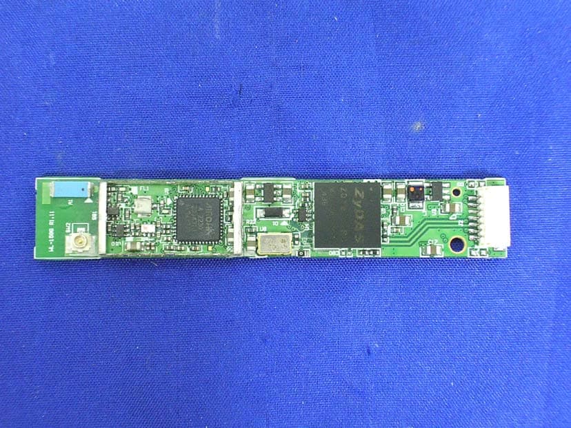
Click to zoom
Application Details
- Equipment Class
- DTS - Digital Transmission System
- Date of Grant
- Jan 12, 2005
- Application Purpose
- Original Equipment
- Date of Application
- Jan 12, 2005
- Equipment Note
- USB2.0 WLAN SLIM MODULE
- Frequency Range
- 2412.00000000 - 2462.00000000
- Company
- ASUSTeK Computer Inc
- Country
- Taiwan
Documents & Files
Document Text
Text extracted from the exhibit documents filed with the FCC. Open a document above to read the original.
Users Manual
1 User’s Manual ASUS WL-159G USB2.0 WLAN Slim Module Version1.1 2004/11/04 2 Contents Notice ............................................................................................... 3 Safety statements ............................................................................ 4 Network setup ................................................................................ 6 Ad-hoc network ...................................................... 6 Infrastructure network ............................................ 6 System requirements..............................................................7 Installing the device drivers. ................................................ ......7 WL-159g specification summary.....................................................11 3 Notices Federal Communications Commission Statement This device complies with FCC Rules Part 15. Operation is subject to the following • This device may not cause harmful interference, and • This device must accept any interference received, including interference that may cause undesired operation. This equipment has been tested and found to comply with the limits for a class B digital device, pursuant to Part 15 of the Federal Communications Commission (FCC) rules. These limits are designed to provide reasonable protection against harmful interference in a residential installation. This equipment generates, uses, and can radiate radio frequency energy and, if not installed and used in accordance with the instructions, may cause harmful interference to radio communications. However, there is no guarantee that interference will not occur in a particular installation. If this equipment does cause harmful interference to radio or television reception, which can be determined by turning the equipment off and on, the user is encouraged to try to correct the interference by one or more of the following measures: • Reorient or relocate the receiving antenna. • Increase the separation between the equipment and receiver. • Connect the equipment into an outlet on a circuit different from that to which the receiver is connected. • Consult the dealer or an experienced radio/TV technician for help. CAUTION! You are cautioned that changes or modifications not expressly approved by the party responsible for compliance could void your authority to operate the equipment. Reprinted from the Code of Federal Regulations #47, part 15.193, 1993. Washington DC: Office of the Federal Register, National Archives and Records Administration, U.S. Government Printing Office. 4 Safety statements Regulatory Information/Disclaimers Installation and use of this Wireless LAN device must be in strict accordance with the instructions included in the user documentation provided with the product. Any changes or modifications (including the antennas) made to this device that are not expressly approved by the manufacturer may void the user’s authority to operate the equipment. The manufacturer is not responsible for any radio or television interference caused by unauthorized modification of this device, or the substitution of the connecting cables and equipment other than manufacturer specified. It is the responsibility of the user to correct any interference caused by such unauthorized modification, substitution or attachment. Manufacturer and its authorized resellers or distributors will assume no liability for any damage or violation of government regulations arising from failing to comply with these guidelines. CAUTION! To maintain compliance with FCC’s RF exposure guidelines, this equipment should be installed and operated with minimum distance [20cm] between the radiator and your body. Use on the supplied antenna. Unauthorized antenna, modification, or attachments could damage the transmitter and may violate FCC regulations. Safety Information In order to maintain compliance with the FCC RF exposure guidelines, this equipment should be installed and operated with minimum distance [20cm] between the radiator and your body. Use only with supplied antenna. Unauthorized antenna, modification, or attachments could damage the transmitter and may violate FCC regulations. CAUTION! Any changes or modifications not expressly approved in this manual could void your authorization to use this device. MPE Statement Your device contains a low power transmitter. When device is transmitted it sends out Radio Frequency (RF) signal. 5 FCC Radio Frequency Exposure This Wireless LAN radio device has been evaluated under FCC Bulletin OET 65C and found compliant to the requirements as set forth in CFR 47 Sections 2.1091, 2.1093, and 15.247(b)(4) addressing RF Exposure from radio frequency devices. The radiation output power of this Wireless LAN device is far below the FCC radio frequency exposure limits. Nevertheless, this device shall be used in such a manner that the potential for human contact during normal operation – as a mobile or portable device but use in a body-worn way is strictly prohibit. When using this device, a certain separation distance between antenna and nearby persons has to be kept to ensure RF exposure compliance. In order to comply with the RF exposure limits established in the ANSI C95.1 standards, the distance between the antennas and the user should not be less than [20cm]. RF Exposure The antenna(s) used for this transmitter must not be co-located or operating in conjunction with any other antenna or transmitter. About this guide This user guide contains the information you your ASUS USB Wireless LAN Module. 6 Network setup The ASUS USB Wireless LAN Adapter may be used in both Ad-hoc and Infrastructure network types. The following sections describe the device functions in these network types. Ad-hoc network In an Ad-hoc network type, the device connects to another wireless LAN adapter in a wireless network. No access point (AP) is present in this wireless environment. Determine your network settings before installing the device to avail all its …
Text truncated - open the document above for the full version.
Cover Letter(s)
ASUSTeK COMPUTER INC. FCC ID.: MSQWL159G 4FL., No. 150, Li-Te Rd., Peitou, Taipei, Taiwan, R.O.C. Tel : +886 2 2894-3447#3183 ASUSTeK COMPUTER INC. 4FL., No. 150, Li-Te Rd., Peitou, Taipei, Taiwan, R.O.C. Tel : +886 2 2894-3447#3183 Fax: +886 2 2895-0113 Federal Communications Commission Nov. 25, 2004 Authorization and Evaluation Division Confidentiality Request Pursuant to Sections 0.457 and 0.459 of the Commission’s Rules, the Applicant Hereby requests confidential treatment of information accompanying this Application As outlined below: Schematics, B lock Diagram The above materials contain trade secrets and proprietary information not customarily Released to the public. The public disclosure of these matters might be harmful to the Applicant and provide unjustified benefits to its competitors. The Applicant understands that pursuant to Rule 0.457, disclosure of this Application and all accompanying documentation will not be made before the date of the Grant for this application. Sincerely, Chennan Liu / Lead Product Manager ASUSTeK COMPUTER INC.
External Photos
Report No.: 04BL015FI Page : 1 of 13 Version:1.0 Attachment 2 : EUT Detailed Photographs (1) EUT Photo (2) EUT Photo Report No.: 04BL015FI Page : 2 of 13 Version:1.0 (3) EUT Photo (4) EUT Photo
ID Label/Location Info
ASUSTeK COMPUTER INC. FCC ID.: MSQWL159G 4FL., No. 150, Li-Te Rd., Peitou, Taipei, Taiwan, R.O.C. . Tel : +886 2 2894-3447#3183 FCC ID AND DoC Label The FCC ID and DoC Label will be placed on the equipment as shown in the photograph below. USB2.0 WLAN Slim Module Model No.: WL-159G USB2.0 WLAN Slim Module Model No.: WL-159G F F C C C C I I D D : : M M S S Q Q W W L L 1 1 5 5 9 9 G G This device complies with Part 15 of the FCC Rules. Operation is subject to the following two conditions: (1) this device may not cause harmful interference and (2) this device must accept any interference received, including interference that may cause undesired operation. S/N: Made in Taiwan
ID Label/Location Info
ASUSTeK COMPUTER INC. FCC ID.: MSQWL159G 4FL., No. 150, Li-Te Rd., Peitou, Taipei, Taiwan, R.O.C. . Tel : +886 2 2894-3447#3183 FCC ID AND DoC Label The FCC ID and DoC Label will be placed on the equipment as shown in the photograph below. USB2.0 WLAN Slim Module Model No.: WL-159G USB2.0 WLAN Slim Module Model No.: WL-159G F F C C C C I I D D : : M M S S Q Q W W L L 1 1 5 5 9 9 G G This device complies with Part 15 of the FCC Rules. Operation is subject to the following two conditions: (1) this device may not cause harmful interference and (2) this device must accept any interference received, including interference that may cause undesired operation. S/N: Made in Taiwan
Internal Photos
Report No.: 04BL015FI Page : 3 of 13 Version:1.0 (5) EUT Photo (6) EUT Photo Report No.: 04BL015FI Page : 4 of 13 Version:1.0 (7) EUT Photo (8) EUT Photo Report No.: 04BL015FI Page : 5 of 13 Version:1.0 (9) EUT Photo (10) EUT Photo Report No.: 04BL015FI Page : 6 of 13 Version:1.0 (11) EUT Photo (12) EUT Photo Report No.: 04BL015FI Page : 7 of 13 Version:1.0 (13) EUT Photo (14) EUT Photo Report No.: 04BL015FI Page : 8 of 13 Version:1.0 (15) EUT Photo (16) EUT Photo Report No.: 04BL015FI Page : 9 of 13 Version:1.0 (17) EUT Photo (18) EUT Photo Report No.: 04BL015FI Page : 10 of 13 Version:1.0 (19) EUT Photo (20) EUT Photo Report No.: 04BL015FI Page : 11 of 13 Version:1.0 (21) EUT Photo (22) EUT Photo Report No.: 04BL015FI Page : 12 of 13 Version:1.0 (23) EUT Photo (24) EUT Photo Report No.: 04BL015FI Page : 13 of 13 Version:1.0 (25) EUT Photo (26) EUT Photo
Operational Description
Report No. 04BL015FI Page: 5 of 100 Version:1.0 1.2. Operational Description EUT is a USB2.0 WLAN Slim Module with 11 channels. This device provided four kinds of transmitting speed 1, 2, 5.5 and 11Mbps. The device of RF carrier is DBPSK, DQPSK and CCK (IEEE 802.11b) or eight kinds of transmitting speed 6, 9, 12, 18, 24, 36, 48 and 54Mbps. The device of RF carrier is OFDM (IEEE 802.11g). The device adapts direct sequence spread spectrum modulation. The antenna was Connector provides diversity function to improve the receiving function. This USB2.0 WLAN Slim Module , compliant with IEEE 802.11b and IEEE 802.11g, is a high-efficiency Wireless LAN adapter. It allows your computer to connect to a wireless network and to share resources, such as files or printers without being bound to the network wires. Operation in 2.4GHz Direst Sequence Spread Spectrum (DSSS) radio transmission, the USB2.0 WLAN Slim Module Wired Equivalent Protection (WEP) algorithm is used. In addition, its standard compliance ensures that it can communicate with any IEEE 802.11b and IEEE 802.11g network.
Test Report
Report No. 04BL015FI Page: 1 of 100 Version:1.0 Test Report Product Name : USB2.0 WLAN Slim Module Model No : WL-159G FCC ID : MSQWL159G Applicant : ASUSTeK COMPUTER INC. Address : 4FL., No. 150, Li-Te Rd., Peitou, Taipei, Taiwan, R.O.C. Date of Receipt : Oct. 27, 2004 Issue Date : Nov. 25, 2004 Report No. : 04BL015FI The test results relate only to the samples tested. The test report shall not be reproduced except in full without the written approval of QuieTek Corporation. This report must not be used to claim product endorsement by NVLAP any agency of the U.S. Government Report No. 04BL015FI Page: 2 of 100 Version:1.0 Test Report Certification Issue Date : Nov. 25, 2004 Report No. : 04BL015FI Test results relate only to the samples tested. The test report shall not be reproduced except in full without the written approval of QuieTek Corporation. This report must not be used to claim product endorsement by NVLAP any agency of the U.S. Government Product Name : USB2.0 WLAN Slim Module Applicant : ASUSTeK COMPUTER INC. Address : 4FL., No. 150, Li-Te Rd., Peitou, Taipei, Taiwan, R.O.C. Manufacturer : ASUSTeK COMPUTER INC. Model No. : WL-159G Rated Voltage : DC 5V(Power by USB interface) Trade Name : ASUS Measurement Standard : FCC CFR Title 47 Part 15 Subpart C: 2003 Measurement Procedure : ANSI C63.4: 2001 Test Result : Complied Documented By : ( Rita Huang ) Tested By : ( Ryan Wu ) Approved By : ( Gene Chang ) Accredited by NIST (NVLAP) NVLAP Lab Code: 200533-0 Report No. 04BL015FI Page: 3 of 100 Version:1.0 TABLE OF CONTENTS Description Page 1. GENERAL INFORMATION .....................................................................................................4 1.1. EUT Description............................................................................................................................4 1.2. Operational Description ................................................................................................................5 1.3. Tested System Datails....................................................................................................................6 1.4. Configuration of tested System .....................................................................................................6 1.5. EUT Exercise Software .................................................................................................................6 1.6. Test Facility ...................................................................................................................................7 2. Conducted Emission....................................................................................................................8 2.1. Test Equipment..............................................................................................................................8 2.2. Test Setup ......................................................................................................................................8 2.3. Limits ............................................................................................................................................8 2.4. Test Procedure ...............................................................................................................................9 2.5. Uncertainty ....................................................................................................................................9 2.6. Test Result of Conducted Emission.............................................................................................10 3. Peak Power Output ...................................................................................................................22 3.1. Test Equipment............................................................................................................................22 3.2. Test Setup ....................................................................................................................................22 3.3. Limits ..........................................................................................................................................22 3.4. Uncertainty ..................................................................................................................................22 3.5. Test Result of Peak Power Output...............................................................................................23 4. Radiated Emission .....................................................................................................................25 4.1. Test Equipment............................................................................................................................25 4.2. Test Setup ....................................................................................................................................25 4.3. Limits ..........................................................................................................................................26 4.4. Test Procedure .............................................................................................................................27 4.5. Uncertainty ..................................................................................................................................27 4.6. Test Result of Radiated Emission................................................................................................28 5. Band Edge ..................................................................................................................................64 5.1. Test Equipment............................................................................................................................64 5.2. Test Setup ....................................................................................................................................64 5.3. Limits ..........................................................…
Text truncated - open the document above for the full version.
Test Setup Photos
Report No.: 04BL015FI Page : 1 of 8 Version:1.0 Attachment 1: EUT Test Setup Photographs Front View of Conducted Test (Mode 1) Back View of Conducted Test (Mode 1) Report No.: 04BL015FI Page : 2 of 8 Version:1.0 Front View of Conducted Test (Mode 2) Back View of Conducted Test (Mode 2) Report No.: 04BL015FI Page : 3 of 8 Version:1.0 Front View of Conducted Test (Mode 3) Back View of Conducted Test (Mode 3) Report No.: 04BL015FI Page : 4 of 8 Version:1.0 Front View of Radiated Test (Mode 1) Back View of Radiated Test (Mode 1) Report No.: 04BL015FI Page : 5 of 8 Version:1.0 Front View of Radiated Test (Mode 2) Back View of Radiated Test (Mode 2) Report No.: 04BL015FI Page : 6 of 8 Version:1.0 Front View of Radiated Test (Mode 3) Back View of Radiated Test (Mode 3) Report No.: 04BL015FI Page : 7 of 8 Version:1.0 Front View of Radiated Test (Horn) (Mode 1) Front View of Radiated Test (Horn) (Mode 2) Report No.: 04BL015FI Page : 8 of 8 Version:1.0 Front View of Radiated Test (Horn) (Mode 3)
Contact Information
Applicant
Jackson Yen(Associate Vice President)
Test Firm
DEKRA Testing and Certification Co., Ltd.Sky Hsu
Technical Specifications
| # | Rule Parts | Frequency Range | Power Output |
|---|---|---|---|
| 1 | 15C | 2.41 GHz - 2.46 GHz | 544.50 mW |
Other Applications from ASUSTeK Computer Inc

MSQ-GC701
Aug 21, 2026Wireless Gaming Controller
Equipment Class
DSS - Part 15 Spread Spectrum TransmitterMSQMPDONGLE3
Aug 18, 2026WIRELESS DONGLE
Equipment Class
DTS - Digital Transmission System
MSQ-GC701D
Aug 13, 2026USB Wireless Dongle
Equipment Class
DSS - Part 15 Spread Spectrum TransmitterMSQ-CM3206DM4A
May 27, 2026Chromebook/Notebook PC
Equipment Class
DCD - Part 15 Low Power Transmitter Below 1705 kHz
MSQ-GST868003
Apr 03, 2026MODULE-WIRELESS CHRG
Equipment Class
DCD - Part 15 Low Power Transmitter Below 1705 kHz