MSQWL167GASUS USB WLAN ADAPTER
ASUSTeK Computer Inc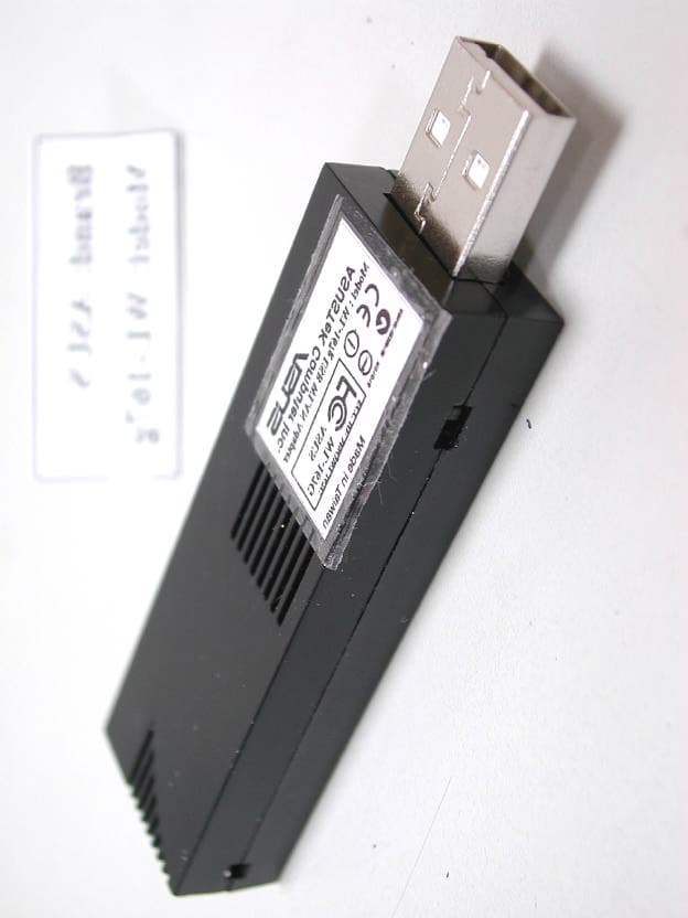
Click to zoom
Application Details
- Equipment Class
- DTS - Digital Transmission System
- Date of Grant
- Aug 22, 2004
- Application Purpose
- Original Equipment
- Date of Application
- Aug 22, 2004
- Equipment Note
- ASUS USB WLAN ADAPTER
- Frequency Range
- 2412.00000000 - 2462.00000000
- Company
- ASUSTeK Computer Inc
- Country
- Taiwan
Documents & Files
Document Text
Text extracted from the exhibit documents filed with the FCC. Open a document above to read the original.
Users Manual
® USB Wireless LAN Adapter (WL-167g) User Guide ii Checklist Copyright © 2004 ASUSTeK COMPUTER INC. All Rights Reserved. No part of this manual, including the products and software described in it, may be reproduced, transmitted, transcribed, stored in a retrieval system, or translated into any language in any form or by any means, except documentation kept by the purchaser for backup purposes, without the express written permission of ASUSTeK COMPUTER INC. (“ASUS”). Product warranty or service will not be extended if: (1) the product is repaired, modified or altered, unless such repair, modification of alteration is authorized in writing by ASUS; or (2) the serial number of the product is defaced or missing. ASUS PROVIDES THIS MANUAL “AS IS” WITHOUT WARRANTY OF ANY KIND, EITHER EXPRESS OR IMPLIED, INCLUDING BUT NOT LIMITED TO THE IMPLIED WARRANTIES OR CONDITIONS OF MERCHANTABILITY OR FITNESS FOR A PARTICULAR PURPOSE. IN NO EVENT SHALL ASUS, ITS DIRECTORS, OFFICERS, EMPLOYEES OR AGENTS BE LIABLE FOR ANY INDIRECT, SPECIAL, INCIDENTAL, OR CONSEQUENTIAL DAMAGES (INCLUDING DAMAGES FOR LOSS OF PROFITS, LOSS OF BUSINESS, LOSS OF USE OR DATA, INTERRUPTION OF BUSINESS AND THE LIKE), EVEN IF ASUS HAS BEEN ADVISED OF THE POSSIBILITY OF SUCH DAMAGES ARISING FROM ANY DEFECT OR ERROR IN THIS MANUAL OR PRODUCT. SPECIFICATIONS AND INFORMATION CONTAINED IN THIS MANUAL ARE FURNISHED FOR INFORMATIONAL USE ONLY, AND ARE SUBJECT TO CHANGE AT ANY TIME WITHOUT NOTICE, AND SHOULD NOT BE CONSTRUED AS A COMMITMENT BY ASUS. ASUS ASSUMES NO RESPONSIBILITY OR LIABILITY FOR ANY ERRORS OR INACCURACIES THAT MAY APPEAR IN THIS MANUAL, INCLUDING THE PRODUCTS AND SOFTWARE DESCRIBED IN IT. Products and corporate names appearing in this manual may or may not be registered trademarks or copyrights of their respective companies, and are used only for identification or explanation and to the owners’ benefit, without intent to infringe. Control Number:E1684 Manual Version:July 2004 iii Features Contents Notice .............................................................................................. v Safety statements ........................................................................... vi About this guide ............................................................................ viii WL-167g specification summary .................................................... ix Chapter 1: Product introduction 1.1Welcome! ........................................................................... 1-2 1.2Package contents ............................................................... 1-2 1.3Features ............................................................................. 1-3 1.4Network setup .................................................................... 1-4 1.4.1Ad-hoc network ...................................................... 1-4 1.4.2Infrastructure network ............................................ 1-4 Chapter 2: Installation 2.1System requirements ......................................................... 2-2 2.2Installation procedures ....................................................... 2-2 2.2.1Installing the device drivers and utilities ................ 2-2 2.2.2Installing the device ............................................... 2-3 Chapter 3: Software support 3.1Control Center .................................................................... 3-2 3.1.1Control Center icons .............................................. 3-2 3.1.2Control Center right-click menu ............................. 3-3 3.1.3Control Center left-click menu ............................... 3-3 iv Safeguards Contents 3.2Wireless Settings ................................................................ 3-4 3.2.1Status ..................................................................... 3-4 3.2.2Configuration ......................................................... 3-7 3.2.3Site Survey ............................................................ 3-9 3.2.4About Wireless Settings ....................................... 3-10 3.2.5Link State ............................................................. 3-10 3.2.6Command icons .................................................... 3-11 3.2.7Other right-click options ........................................ 3-11 3.3Mobile Manager ................................................................ 3-13 3.3.2Creating a new configuration ............................... 3-15 3.3.3Editing a configuration ......................................... 3-19 3.4Site Monitor ...................................................................... 3-23 3.4.1Launching Site Monitor ........................................ 3-23 3.4.2Site Monitor main window .................................... 3-23 3.4.3Monitoring a connection ....................................... 3-24 Chapter 4: Troubleshooting Troubleshooting ........................................................................... 4-2 v Notices Federal Communications Commission Statement This device complies with FCC Rules Part 15. Operation is subject to the following two conditions: •This device may not cause harmful interference, and •This device must accept any interference received, including interference that may cause undesired operation. This equipment has been tested and found to comply with the limits for a class B digital device, pursuant to Part 15 of the Federal Communications Commission (FCC) rules. These limits are designed to provide reasonable protection against harmful interference in a residential installation. This equipment generates, uses, and can radiate radio frequency energy and, if not installed and used in accordance with the instructions, may cause harmful interference to radio communications. However, there is no guarantee that interference will not occur in a particular installation. If this equipment does cause harmful interference to radio or television reception, which can be determined by turning the equipment off and…
Text truncated - open the document above for the full version.
Users Manual
Chapter 3 This chapter provides information on the softwares and utilities inside the support CD Software support 3-2Chapter 3: Software support 3.1 Control Center The Control Center utility is a management software that launches applications and configures network settings. The Control Center starts automatically when the system boots and displays the Control Center icon in the Windows ® taskbar. The Control Center icon serves as an application launcher, and indicator of signal quality and Internet connection. 3.1.1 Control Center icons The Control Center icon indicates the quality of link to the access point and connection to the Internet. Refer to the table below for icon indications. Infrastructure network (wireless LAN adapter to an access point) Excellent link quality andExcellent link quality but not connected to the Internetconnected to the Internet Good link quality andGood link quality but not connected to the Internetconnected to the Internet Fair link quality andFair link quality but not connected to the Internetconnected to the Internet Poor link quality butPoor link quality and not connected to the Internetconnected to the Internet Not linked but connectedNot linked and not to the Internetconnected to the Internet Ad-hoc network (wireless LAN adapter to other Wi-Fi device) Linked Not Linked Connected to the Internet ASUS USB wireless LAN adapter3-3 3.1.2 Control Center right-click menu Right-clicking the Control Center icon displays the softwares and utilities the ASUS USB Wireless LAN Adapter supports. Refer to the succeeding sections for details on these utilities and softwares. 3.1.3 Control Center left-click menu Left-clicking the Control Center icon displays the left-click menu. Search & Connect – View available wireless networks within range. Wireless Option – Sets your Windows ® XP wireless networking environment. The Wireless Option window appears when you select this option. Select “Only use ASUS utilities and disable XP wireless function”to avail all ASUS USB wireless LAN adapter features. ClickOK. 3-4Chapter 3: Software support 3.2 Wireless Settings The Wireless Settings is the main interface that allows you to control the ASUSUSBwireless LAN adapter. Use the Wireless Settings to view the operational and connection status, or to modify the wireless LAN adapter configuration. The Wireless Settings window is composed of the property window and tabbed property sheets. Click the icons in the property window to display their tabbed property sheets. Property window Tabbed property sheets 3.2.1 Status Status tab The Status tab provides general information on the wireless LAN adapter. Association State. This field displays the connection status and MAC address of the network where the system is connected. Service Set Identifier (SSID). This field displays the SSID of the network to which the card is associated or is intending to join. The SSIDis a group name shared by every member of a wireless network. Only client PCs with the same SSID are allowed to establish a connection. TheMAC Address field displays the hardware address of a device connected to a network. TheCurrent Channel field displays the radio channel that the card is currently tuned. The channel changes as wireless LAN adapter scans the available channels. TheCurrent Data Rate field displays the data transfer rate between the wireless LAN adapter and the access point. ASUS USB wireless LAN adapter 3-5 IP Config tab The IP Config tab displays the current host and Ethernet adapter configurations. IP Config displays TCP/IP information including the IP address, subnet mask, default gateway, DNS and Windows Internet Naming Service (WINS) configurations. Use the IP Config Tab to verify your network settings. IP Release. Click to release the DHCP IP address for the wireless LAN adapter. IP Renew. Click to renew the DHCP IP address for the wireless LAN adapter. Ping. Click to display the Ping tab. Use ping to verify a connection to a particular host name or IP address. Connection tab The Connection tab provides real-time information on connection throughput, frame errors, signal strength, link quality and overall connection quality in graphical representation. Rescan button - Click to allow wireless LAN adapter to scan available wireless networks and to connect to the network with the best signal quality. Change SSID button - Click to change the SSID. Clicking this button opens the Config-Basic window. See “Basic tab” on page 3-7. Search and Connect button - Click to view all wireless networks within the range of your system. Clicking this button opens the Site Survey window. See page 3-9. The IP Release and IP Renew buttons may only be used on a DHCP-configured wireless LAN adapter. 3-6Chapter 3: Software support Ping tab The Ping tab allows you to verify the connection of your computer with another computer in a network. To ping a connection: 1. Type the IP address of the connection you want to verify in theIP Address field. 2. Configure the ping session by assigning the size and count of packet to send, and the time limit for a ping session to continue (in milliseconds). 3. Click the Pingbutton. During the ping session, the Ping button toggles into a Stopbutton. ClickStopanytime to cancel the ping session. The session field displays information on the verified connection including the roundtrip time (minimum, maximum, and average) and packets sent, received, and lost after a ping session. Click the Clear button to clear the session field. ASUS USB wireless LAN adapter3-7 3.2.2 Configuration Basic tab TheBasictab provides general information on network types and other configurations. Network Type. Select the type of network that you wish to use. Select Infrastructure mode to establish a connection with an access point (AP). In this mode, your system can access wireless LAN and wired LAN (Ethernet) via the AP. Select the Ad Hocmode to communicate directly with other mobile clients within the wireless LAN adapter ran…
Text truncated - open the document above for the full version.
Cover Letter(s)
ASUSTeK COMPUTER INC. Tel : +886-2-28943447 Fax : +886-2-28950114 www.asus.com Request for Confidentiality Federal Communications Commission Authorization and Evaluation Division Subject: Confidentiality Request regarding application for certification of FCC ID: MSQWL167G Dear Madam or Sir: Pursuant to Sections 0.457 and 0.459 of the Commission’s Rules, we hereby request confidential treatment of information accompanying this application as outlined below: l Schematics l Part List l Block diagram l Operational description The above materials contain trade secrets and proprietary information not customarily released to the public. The public disclosure of these materials may be harmful to the applicant and provide unjustified benefits to its competitors. The applicant understands that pursuant to Section 0.457 of the Rules, disclosure of this application and all accompanying documentation will not be made before the date of the Grant for this application. ASUSTeK COMPUTER INC. Tel : +886-2-28943447 Fax : +886-2-28950114 www.asus.com Pursuant to DA 04-1705 June 15, 2004 of the Commission’s public notice, we also request temporary confidential treatment of information accompanying this application as outlined below: l External Photos l Internal Photos l Test Setup Photos l User’s Manual Sincerely, Lawrence Yu / Manager ASUSTek Computer Inc.
External Photos
External Photos of USB Wireless LAN Adapter 1/10 Applicant: ASUSTeK Computer Inc. FCC ID: MSQWL167G Training Research Co., Ltd., TEL: 886-2-26935155, Fax: 886-2-26934440 External Photos of USB Wireless LAN Adapter 2/10 Applicant: ASUSTeK Computer Inc. FCC ID: MSQWL167G Training Research Co., Ltd., TEL: 886-2-26935155, Fax: 886-2-26934440 External Photos of USB Wireless LAN Adapter 3/10 Applicant: ASUSTeK Computer Inc. FCC ID: MSQWL167G Training Research Co., Ltd., TEL: 886-2-26935155, Fax: 886-2-26934440 External Photos of USB Adapter 4/10 Applicant: ASUSTeK Computer Inc. FCC ID: MSQWL167G Training Research Co., Ltd., TEL: 886-2-26935155, Fax: 886-2-26934440 External Photos of USB Cable 5/10 Applicant: ASUSTeK Computer Inc. FCC ID: MSQWL167G Training Research Co., Ltd., TEL: 886-2-26935155, Fax: 886-2-26934440
ID Label/Location Info
LABEL Sample and Location information -------------------------------------------------- 2/2 Applicant: ASUSTeK Computer Inc. FCC ID: MSQWL167G Training Research Co., Ltd., TEL: 886-2-26935155, Fax: 886-2-26934440 LABEL Position:
ID Label/Location Info
LABEL Sample and Location information -------------------------------------------------- 1/2 Applicant: ASUSTeK Computer Inc. FCC ID: MSQWL167G Training Research Co., Ltd., TEL: 886-2-26935155, Fax: 886-2-26934440 LABEL Format: 20mm x 15mm FCC ID: MSQWL167G
Internal Photos
Internal Photos of USB Wireless LAN Adapter ---------------------------------------- 6/10 Applicant: ASUSTeK Computer Inc. FCC ID: MSQWL167G Training Research Co., Ltd., TEL: 886-2-26935155, Fax: 886-2-26934440 Internal Photos of USB Wireless LAN Adapter ---------------------------------------- 7/10 Applicant: ASUSTeK Computer Inc. FCC ID: MSQWL167G Training Research Co., Ltd., TEL: 886-2-26935155, Fax: 886-2-26934440 Internal Photos of USB Wireless LAN Adapter ---------------------------------------- 8/10 Applicant: ASUSTeK Computer Inc. FCC ID: MSQWL167G Training Research Co., Ltd., TEL: 886-2-26935155, Fax: 886-2-26934440 Internal Photos of USB Wireless LAN Adapter ---------------------------------------- 9/10 Applicant: ASUSTeK Computer Inc. FCC ID: MSQWL167G Training Research Co., Ltd., TEL: 886-2-26935155, Fax: 886-2-26934440 Internal Photos of USB Adapter ---------------------------------------------------------- 10/10 Applicant: ASUSTeK Computer Inc. FCC ID: MSQWL167G Training Research Co., Ltd., TEL: 886-2-26935155, Fax: 886-2-26934440
Test Report
Test Report ----------------------------------------------------------------------------------1/55 Report No.: A5415729, FCC Part 15.247 Training Research Co., Ltd., TEL: 886-2-26935155, Fax: 886-2-26934440 MEASUREMENT REPORT of USB Wireless LAN Adapter Applicant:ASUSTek Computer Inc. EUT:USB WLAN Adapter Model No.:WL-167G FCC ID:MSQWL167G Report No.:A5415729 Tested by : Training Research Co., Ltd. TEL : 886-2-26935155 FAX : 886-2-26934440 No. 255, Nanyang Street, Shijr, Taipei Hsien 221, Taiwan, R.O.C. Test Report ----------------------------------------------------------------------------------2/55 Report No.: A5415729, FCC Part 15.247 Training Research Co., Ltd., TEL: 886-2-26935155, Fax: 886-2-26934440 CERTIFICATION We here by verify that: The test data, data evaluation, test procedures and equipment configurations shown in this report were made mainly in accordance with the procedures given in ANSI C63.4 (1992) as a reference. All test were conducted byTraining Research Co., Ltd., 255 Nanyang Street, Shijr, Taipei Hsien 221, Taiwan, R.O.C. Also, we attest to the accuracy of each. We further submit that the energy emitted by the sample EUT tested as described in the report is in compliance with the technical requirements set forth in the FCC Rules Part 15 Subpart B (Declaration of Conformity) and C Section 15.247. Applicant:ASUSTek Computer Inc. Applicant address:4F, No. 150, Li-Te Rd., Peitou, Taipei, Taiwan, R.O.C. Product Name:ASUS USB Wireless LAN Adapter Model Name:WL-167G FCC ID:MSQWL167G Report No.:A5415729 Test Date:August 3, 2004 Prepared by:Approved by: Jack TsaiFrank Tsai Conditions of issue : (1) This test report shall not be reproduced except in full, without written approval of TRC. And the test result contained within this report only relate to the sample submitted for testing. (2) This report must not be used by the client to claim product endorsement by NVLAP or any agency of U.S. Government. (3) This test report, measurements made by TRC are traceable to the NIST only Conducted and Radiated Method. NVLAP LAB CODE: 200174-0 Test Report ----------------------------------------------------------------------------------3/55 Report No.: A5415729, FCC Part 15.247 Training Research Co., Ltd., TEL: 886-2-26935155, Fax: 886-2-26934440 Federal Communications Commission Declaration of Conformity (DoC) for the following equipment: Product name:USB Wireless LAN Adapter Model name:WL-167G Trade name:ASUS Is herewith confirmed and found to comply with the requirements of CFR 47 part15 Subpart B - Unintentional Radiators regulation. The results of electromagnetic mission evaluation are shown in the report number : A5415729 This device complies with Part 15 of the FCC Rules. Operation is subject to the following two conditions: (1) This device may not cause harmful interference, and (2) This device must accept any interference received, including interference that may cause undesired operation ManufacturerUSA local representative Company name: ASUSTeK Computer Inc.To be determined Computer address: 4/F, 150, Li-Te Rd., Peitou, Taipei, Taiwan ZIP / Postal code 112 Contact person: Lawrence Yu Title: Manager Internet e-mail address: [email protected] Tel / Fax: 886-2-28943447 / 886-2-28950113 Test Report ----------------------------------------------------------------------------------4/55 Report No.: A5415729, FCC Part 15.247 Training Research Co., Ltd., TEL: 886-2-26935155, Fax: 886-2-26934440 Tables of Contents I.GENERAL................................................................................................................... 6 1.1Introduction ......................................................................................................... 6 1.2Description of EUT ............................................................................................. 6 1.3Test method ......................................................................................................... 6 1.4Description of Support Equipment ...................................................................... 7 1.5Configuration of System Under Test ................................................................... 9 1.6Verify the Frequency and Channel ..................................................................... 11 1.7Test Procedure .................................................................................................... 12 1.8Location of the Test Site ..................................................................................... 12 1.9General Test Condition ...................................................................................... 12 II.Section 15.101(a) : Equipment Authorization of Unintentional Radiators............ 13 III. Section 15.203 : Antenna Requirement...................................................................... 14 IV. Section 15.207 : Power Line Conducted Emissions for AC Powered Units......... 15 4.1Test Condition & Setup ...................................................................................... 15 4.2List of Test Instruments ...................................................................................... 16 4.3Test Result of Conducted Emissions .................................................................. 17 R/W mode ..................................................................................................................... 17 Standby mode ................................................................................................................ 18 IEEE 802.11b ................................................................................................................ 19 IEEE 802.11g ................................................................................................................ 20 V.Section 15.247(a) : Technical Description of the EUT.............................................. 22 VI. Section 15.247(a)(2) : Bandwidth for Direct Sequence System........................…
Text truncated - open the document above for the full version.
Test Setup Photos
Test Setup Photos ------------------------------------------------------------------------1/4 Applicant: ASUSTeK Computer Inc. FCC ID: MSQWL167G Training Research Co., Ltd., TEL: 886-2-26935155, Fax: 886-2-26934440 Conducted Test Setup Placement: (EUT with USB cable) Front View of the Test Configuration Side View of the Test Configuration Test Setup Photos ------------------------------------------------------------------------2/4 Applicant: ASUSTeK Computer Inc. FCC ID: MSQWL167G Training Research Co., Ltd., TEL: 886-2-26935155, Fax: 886-2-26934440 Conducted Test Setup Placement: (EUT with USB adapter) Front View of the Test Configuration Side View of the Test Configuration Test Setup Photos ------------------------------------------------------------------------3/4 Applicant: ASUSTeK Computer Inc. FCC ID: MSQWL167G Training Research Co., Ltd., TEL: 886-2-26935155, Fax: 886-2-26934440 Radiated Test Setup Placement: (EUT with USB cable) Front View of the Test Configuration Rear View of the Test Configuration Test Setup Photos ------------------------------------------------------------------------4/4 Applicant: ASUSTeK Computer Inc. FCC ID: MSQWL167G Training Research Co., Ltd., TEL: 886-2-26935155, Fax: 886-2-26934440 Radiated Test Setup Placement: (EUT with USB adapter) Front View of the Test Configuration Rear View of the Test Configuration
Contact Information
Applicant
Jackson Yen(Associate Vice President)
Test Firm
Training Research Co., Ltd.YuYu Tzeng
Technical Specifications
| # | Rule Parts | Frequency Range | Power Output |
|---|---|---|---|
| 1 | 15C | 2.41 GHz - 2.46 GHz | 14.00 mW |
Other Applications from ASUSTeK Computer Inc

MSQ-GC701
Aug 21, 2026Wireless Gaming Controller
Equipment Class
DSS - Part 15 Spread Spectrum TransmitterMSQMPDONGLE3
Aug 18, 2026WIRELESS DONGLE
Equipment Class
DTS - Digital Transmission System
MSQ-GC701D
Aug 13, 2026USB Wireless Dongle
Equipment Class
DSS - Part 15 Spread Spectrum TransmitterMSQ-CM3206DM4A
May 27, 2026Chromebook/Notebook PC
Equipment Class
DCD - Part 15 Low Power Transmitter Below 1705 kHz
MSQ-GST868003
Apr 03, 2026MODULE-WIRELESS CHRG
Equipment Class
DCD - Part 15 Low Power Transmitter Below 1705 kHz