MSQWLAPEWL300WLAN Access Point
ASUSTeK Computer Inc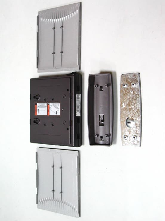
Click to zoom
Application Details
- Equipment Class
- DTS - Digital Transmission System
- Date of Grant
- Feb 20, 2002
- Application Purpose
- Original Equipment
- Date of Application
- Feb 20, 2002
- Equipment Note
- WLAN Access Point
- Frequency Range
- 2412.00000000 - 2462.00000000
- Company
- ASUSTeK Computer Inc
- Country
- Taiwan
Documents & Files
Document Text
Text extracted from the exhibit documents filed with the FCC. Open a document above to read the original.
Users Manual
Regulatory information / Disclaimers Installation and use of this Wireless LAN device must be in strict accordance with the instructions included in the user documentation provided with the product. Any changes or modifications (including the antennas) made to this device that are not expressly approved by the manufacturer may void the user’s authority to operate the equipment. The manufacturer is not responsible for any radio or television interference caused by unauthorized modification of this device, or the substitution or o\attachment of connecting cables and equipment other than manufacturer specified. It is the responsibility of the user to correct any interference caused by such unauthorized modification, substitution or attachment. Manufacturer and its authorized resellers or distributors will assume no liability for any damage or violation of government regulations arising from failing to comply with these guidelines.
Users Manual
Any changes of modifications not expressly approved by the grantee of this device could void the users authority to operate the equipment. CAUTION: To maintain compliance with FCC’s RF exposure guidelines, this equipment should be installed and operated with minimum distance 20cm between the radiator and your body. Use on the supplied antenna. Unauthorized antenna, modification, or attachments could damage the transmitter and may violate FCC regulations.
Block Diagram
Antenna T/R Switch ISL3685 RF- IF Conversion SAW Filter IF=374MHz BW=22MHz HFA3783 IF-Baseband Conversion RF VCO 2038~2110 MHz HFA3861B DSSS Baseband Processor AT76C510 CPU and MAC Crystal Oscillator 44MHz IF VCO 748MHz XTAL 12MHz XTAL 32MHz SRAM 512K*8 Flash 512K*8 RTL8201L Ethernet PHY XTAL 25MHz Ethernet to PC ISL3984 Power Amplifer RX Thicker arrow means TX path Thiner arrow means RX path ASUS WLAN AP SYSTEM BLOCK RF=2.412~2.484GHz RF=2.412~2.484GHz LAN Switch (PI5L) Lattice (CPLD)
ID Label/Location Info
This device complies with Part 15 of the FCC Rules. Operation is subject to the following two conditions: (1) This device may not cause harmful interference. (2) This device must accept any interference received, including interference that may cause undesired operation.
Operational Description
Operation Principles ATMEL AT76C510A RISC CPU with IEEE802.11b MAC layer. ??Wireless interface following the IEEE 802.11b standard. ??Ethernet MAC unit interfaces with 10/100 Mbit Ethernet Physical through a standard MII port. ??Internetworking unit with integrated ARM7TDMI RSIC processor provides the bridging functions between Ethernet and wireless interfaces. ??WLAN MAC unit with a second ARM7TDMI RSIC processor. ??Supports data rat of 1Mbps, 2Mbps, 5.5 Mbps and 11Mbps, with automatic fallback. ??Supports Wire Equivalence Privacy (WEP) as in IEEE802.11. ??Digital interface with HFA3861B, the DSSS baseband processor. ??A 32MHz oscillator is used to provide main clock of the RISC CPU. Flash ROM and SRAMMemory resources of CPU. ??Flash ROM is nonvolatile memory. Firmware program is stored in flash ROM. ??SRAM is volatile memory resource for CPU operation. REALTEK RTL8201LEthernet PHY. ??Single Chip 100Base-TX /10Base-T Physical Layer Solution. ??MII interface to Ethernet Controller. ??Using 25MHz crystal as clock source. ??10 Base transmit functionThe transmitted 4 bits nibble (TXD[0:3]) clocked in 2.5MHz(TXC) is first feed to parallel to serial converter, then put the 10MHz NRZ signal to Manchester coding. The Machester encoder converts the 10Mbps NRZ data into a Manchester Encoded data stream for the TP transmitter and adds a start of idle pulse (SOI) at the end of the packet as specified in IEEE802.3. Then, the encoded data stream is shaped by band-limited filter embedded in RTL8201 and then transmitted to TP line. ??10 Base receive functionIn 10Base receive mode, the Manchester decoder in RTL8201 converts the Manchester encoded data stream from the TP receiver into NRZ data by decoding the data and stripping off the SOI pulse. The, the serial NRZ data stream is converted to parallel 4 bit nibble signal (RXD [0:3]) PI5L200Precision Wide Bandwidth LanSwitch QUAD 2:1 MUX/DEMUX. IM4A3-32 ispMACH 4A CPLD family. High performance E^2 CMOS. In-system programmable logic. HFA3861BDSSS baseband processor. ??Complete Direct Sequence Spread Spectrum (DSSS) baseband processor. ??Supporting Differential Binary Phase Shift Keying (DBPSK), Differential Quadrature Phase Shift Keying (DQPSK) and Complementary Code Keying (CCK). ??As a PHY layer in IEEE802.11b. Data Rate (Mbps) 1 2 5.5 11 Modulation DBPSK DQPSK CCK CCK ??FCC compliant processing gain. ??On-chip A/D and D/A converters for I/Q data (6bit, 22MSPS), AGC, and Adaptive power control (7-bit). ??Supports short preamble acquisition and antenna diversity. ??Transmitter operationDigital data form MAC layer is modulated to produce analog I/Q baseband signal for transmission. When MAC asserts begin of transmission, HFA3681B generate preamble and header itself. After combining with data sent from MAC, all of the data, depends on different data rate, are modulated by the modulation skim listed above. The modulated data pass through a digital LPF. At last, a on-chip D/A converter converts digital data to analog data and then outputs balanced differential analog signals TXI±, TXQ± ??Reception operationReceived analog I/Q baseband signal is demodulated into digital data and sent to MAC layer. Baseband spectrum occupies 0~11MHz, for any of the above modulation or data rate. ??Operating clock is provided by a 44MHz oscillator. HFA3783I/Q modulator/demodulator. ??Integrating all IF transmit and receive functions. ??Integrating IF transmission and reception AGC. ??Integrating a receiver DC offset calibration loop. ??Baseband I/Q signals are combined and converted to IF (Intermediate Frequency). IF center frequency is 374MHz, Bandwidth is 22MHz. IF signal are IF_TX± and IF_RX± and IF RX+. IF signals are sent to or from a SAW filter, and then up and down converted to RF by ISL3685. Baseband I/Q signals are TXI±, TXQ±, RXI± and RXQ±. Baseband I/Q signals are fed from or to the baseband processor, HFA3861B. ??An on chip frequency synthesizer cooperates with IF VCO is used to generate the 374MHz Local Oscillator frequency required by the up-down mixer. The 44MHz oscillator provides the reference frequency required by the frequency synthesizer. ??ISL3685RF to IF converter. ??A low noise, gain selectable amplifier (LNA) followed by a down-converter mixer is integrated. ??An up-converter mixer and a high performance preamplifier compose the transmit chain. ??Integrating a high frequency PLL synthesizer with a three wire programmable interface for LO applications. ??For receiver path, RF signal passes through a LNA with down-conversion mixer and then be converted to IF (374MHz) signal. For transmission path, signal from SAW filter is up converted to RF and amplified by preamplifier. The output is fed to MAX2242 power amplifier. ??An on chip frequency synthesizer is used to generate the Local Oscillator frequency, 2.038~2.110GHz, required by the mixer. An external VCO of 2.074GHz center frequency is used in the frequency synthesizer loop. The 44Mhz oscillator provides the reference frequency required by the frequency synthesizer. ??ISL3984power amplifier for transmission. ??T/R switchTransmission or reception multiplexing switch. ??Transmission/reception are half duplex.
Test Report
Test Report ----------------------------------------------------------------------------- 1/49 MEASUREMENT REPORT of WIRELESS ACCESS POINT Applicant : ASUSTeK Computer Inc. Model No. : WL300 EUT : ASUS SpaceLink Wireless LAN Access Point FCC ID : MSQWLAPEWL300 Report No. : A5415983 Tested by : Training Research Co., Ltd. TEL : 886-2-26935155 FAX : 886-2-26934440 2, Lane 194, Huan-Ho Street, Hsichih, Taipei Hsien 221, Taiwan, R.O.C. Report No.: A5415983 Training Research Co., Ltd., TEL: 886-2-26935155, Fax: 886-2-26934440 Test Report ----------------------------------------------------------------------------- 3/49 Report No.: A5415983 Training Research Co., Ltd., TEL: 886-2-26935155, Fax: 886-2-26934440 Tables of Contents I. GENERAL ....................................................................................................................... 5 1.1 Introduction ................................................................................................................ 5 1.2 Description of EUT .................................................................................................... 5 1.3 Description of Support Equipment ............................................................................ 6 1.4 Configuration of System Under Test ......................................................................... 7 1.5 Verify the Frequency and Channel ............................................................................ 7 1.6 Test Procedure ........................................................................................................... 8 1.7 Location of the Test Site ............................................................................................ 9 1.8 General Test Condition .............................................................................................. 9 II. Section 15.203 : Antenna Requirement.......................................................................... 10 III. Section 15.207: Power Line Conducted Emissions for AC Powered Units ............... 11 3.1 Test Condition & Setup ............................................................................................ 11 3.2 List of Test Instruments ............................................................................................ 11 3.3 Test Configuration .................................................................................................... 12 3.4 Test Result of Conducted Emissions ........................................................................ 13 IV. Section 15.247(a) : Technical Description of the EUT.................................................. 16 V. Section 15.247(a)(2): Bandwidth for Direct Sequence System ................................... 17 5.1 Test Condition & Setup ............................................................................................ 17 5.2 Test Instruments Configuration ................................................................................ 17 5.3 List of Test Instruments ............................................................................................ 17 5.4 Test Result of Bandwidth .......................................................................................... 18 VI. Section 15.247(b) : Power Output ................................................................................. 22 6.1 Test Condition & Setup ............................................................................................ 22 6.2 List of Test Instruments ............................................................................................ 23 6.3 Test Result ................................................................................................................ 23 VII. Section 15.247(c) : Spurious Emissions (Radiated) ..................................................... 30 7.1 Test Condition & Setup ............................................................................................ 30 7.2 List of Test Instruments ............................................................................................ 31 7.3 Test Instruments Configuration ................................................................................ 32 7.4 Test Result of Spurious Radiated Emissions ............................................................ 33 7.5 Test Result of Bandedge ............................................................................................. 40 VIII.Section 15.247(d) : Power Spectral Density ............................................................... 43 8.1 Test Condition & Setup ............................................................................................ 43 8.2 Test Instruments Configuration ................................................................................ 43 8.3 List of Test Instruments .............................................................................................. 43 8.4 Test Result of Power Spectral Density ..................................................................... 44 Test Report ----------------------------------------------------------------------------- 4/49 Report No.: A5415983 Training Research Co., Ltd., TEL: 886-2-26935155, Fax: 886-2-26934440 Appendix A: Set Up Procedure ............................................................................................ 48 Appendix B: Antenna Specification .................................................................................... 49 Test Report ----------------------------------------------------------------------------- 5/49 Report No.: A5415983 Training Research Co., Ltd., TEL: 886-2-26935155, Fax: 886-2-26934440 I. GENERAL 1.1 Introduction The following measurement report is submitted on behalf of Applicant in support of a wireless access point certification in accordance with Part 2 Subpart J and Part 15 Subpart A and C of the Commission's Rules and Regulations. 1.2 Description of EUT EUT : ASUS SpaceLink Wireless LAN Acc…
Text truncated - open the document above for the full version.
Test Setup Photos
Test Instruments Configuration of Conducted Emissions Test Instruments Configuration of Bandwidth Test Configuration of Bandwidth for Direct Sequence System P.S.: Notebook computer to control the EUT at maximal power output and channel Number and set antenna kit Test Condition & Setup of Power Output A: B: EUT Spectrum Analyzer (RBW:100kHz; VBW: 100kHz) EUT HSMS-2850 Oscilloscope HSMS-2850 Oscilloscope Signal Generator Test Instruments Configuration of the Spurious Radiated Emissions Front View of the Test Configuration Rear View of the Test Configuration The test configuration for frequency between 1GHz to 18GHz is same as above. Test Instruments Configuration of Power Spectral Density Test Configuration of Power Spectral Density P.S.: Notebook computer to control the EUT at maximal power output and channel Number and set antenna kit EUT Spectrum Analyzer (RBW:3kHz; VBW: 10kHz)
Contact Information
Applicant
Jackson Yen(Associate Vice President)
Technical Contact
Training Research Co., LtdJack Tsai
[email protected]+886 2 26935155
2, Lane 194, Hun Ho Street, Hsichih · Taipei Hsien · Taiwan
Test Firm
Training Research Co., Ltd.Jack Tsai
Technical Specifications
| # | Rule Parts | Frequency Range | Power Output |
|---|---|---|---|
| 1 | 15C | 2.41 GHz - 2.46 GHz | 27.90 mW |
Other Applications from ASUSTeK Computer Inc

MSQ-GC701
Aug 21, 2026Wireless Gaming Controller
Equipment Class
DSS - Part 15 Spread Spectrum TransmitterMSQMPDONGLE3
Aug 18, 2026WIRELESS DONGLE
Equipment Class
DTS - Digital Transmission System
MSQ-GC701D
Aug 13, 2026USB Wireless Dongle
Equipment Class
DSS - Part 15 Spread Spectrum TransmitterMSQ-CM3206DM4A
May 27, 2026Chromebook/Notebook PC
Equipment Class
DCD - Part 15 Low Power Transmitter Below 1705 kHz
MSQ-GST868003
Apr 03, 2026MODULE-WIRELESS CHRG
Equipment Class
DCD - Part 15 Low Power Transmitter Below 1705 kHz