MU4CKW2000AM / FM Weather Alarm Clock Radio
Lasco Industries Limited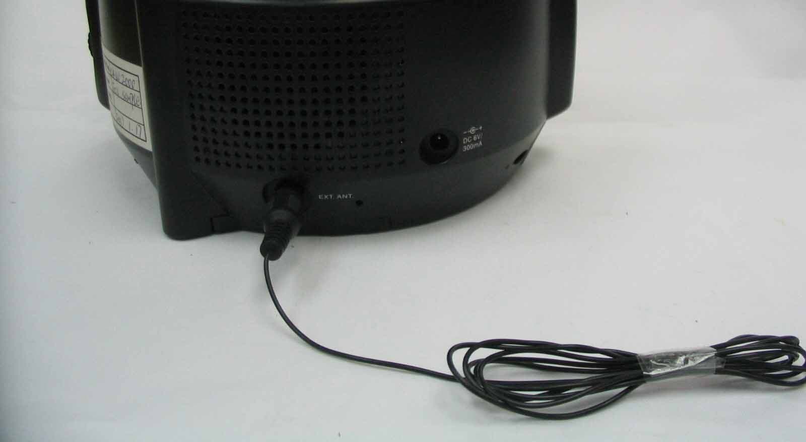
Click to zoom
Application Details
- Equipment Class
- CXX - Communications Rcvr for use w/ licensed Tx and CBs
- Date of Grant
- Apr 01, 2007
- Application Purpose
- Original Equipment
- Date of Application
- Apr 01, 2007
- Equipment Note
- AM / FM Weather Alarm Clock Radio
- Frequency Range
- 162.40000000 - 162.55000000
- Company
- Lasco Industries Limited
- Country
- Hong Kong
Documents & Files
Document Text
Text extracted from the exhibit documents filed with the FCC. Open a document above to read the original.
Users Manual
OWNER’S MANUAL CKW2000 Visit our web site at www.emersonradio.com All-Alert System Clock Radio With Dual Alarms, Digital Tuning And Specific Area Message Encoding R CKW2000_032307.p6523/3/2007, 10:5042 1 TO PREVENT FIRE OR SHOCK HAZARD, DO NOT USE THIS PLUG WITH AN EXTENSION CORD, RECEPTACLE OR OTHER OUTLET UNLESS THE BLADES CAN BE FULLY INSERTED TO PREVENT BLADE EXPOSURE. TO PREVENT FIRE OR SHOCK HAZARD, DO NOT EXPOSE THIS APPLIANCE TO RAIN OR MOISTURE. I MPORTANT SAFETY INSTRUCTIONS 1.)Read these instructions. Keep these instructions. Follow all instructions. Heed all warnings. 2.)Do not use this apparatus near water. 3.)Clean only with dry cloth. 4.)Do not block any ventilation openings. Install in accordance with the manufacturer’s instructions. 5.)Do not install near any heat sources such as radiators, heat registers, stoves, or other apparatus (including amplifiers) that produce heat. 6.)Do not defeat the safety purpose of the polarized or grounding-type plug. A polarized plug has two blades with one wider than the other. A grounding type plug has two blades and a third grounding prong. The wide blade or the third prong is provided for your safety. If the provided plug does not fit into your outlet, consult an electrician for replacement of the obsolete outlet. 7.)Protect the power cord from being walked on or pinched particularly at plugs, convenience receptacles, and the point where they exit from the apparatus. 8.)Only use attachments / accessories specified by the manufacturer. 9.)Unplug this apparatus during lightning storms or when unused for long periods of time. 10.)Refer all servicing to qualified service personnel. Servicing is required when the apparatus has been damaged in any way, such as power-supply cord or plug is damaged, liquid has been spilled or objects have fallen into the apparatus, the apparatus has been exposed to rain or moisture, does not operate normally, or has been dropped. 11.)This appliance shall not be exposed to dripping or splashing water and no object filled with liquids such as vases shall be placed on the apparatus. 12.)Use only with the cart, stand, tripod, bracket, or table specified by the manufacturer, or sold with the apparatus. When a cart is used, use caution when moving the cart/apparatus combination to avoid injury from tip-over. 13.)Do not overload wall outlet. Use only power source as indicated. 14.)Use replacement parts as specified by the manufacturer. 15.)The product may be mounted to a wall only if recommended by the manufacturer. 16.)Upon completion of any service or repairs to this product, ask the service technician to perform safety checks. ! C A U T I O N RISK OF ELECTRIC SHOCK DO NOT OP EN The lightning flash with arrow- head sym bol, within an equi- lateral triangle is intended to alert the user to the presence of uninsulated ‘dangerous voltage’ within the product’s enclosure th at m a y be of su ffi cie nt magnitude to constitute a risk of electric shock to persons. The exclamation point within an equilateral triangle is in- tended to alert the user to the presence of important operating and maintenance (s er vi ci ng ) ins tr uc ti on s in th e lit er at ure a cco mp an y- in g th e ap pl ia nc e. WARNING: TO REDUCE THE RISK OF ELECTRIC SHOCK DO NOT REMOVE COVER ( O R B A C K ) , N O U S E R SERVICEABLE PARTS INSIDE R E F E R S E R V I C I N G T O Q U A L I F I E D S E R V I C E PERSONNEL. C A U T I O N The Caution Marking maybe located at the rear enclosure of the apparatus. CKW2000_032307.p6523/3/2007, 10:501 2 Thank you for purchasing this All-Alert Clock Radio from Emerson Research. This model incorporates the All-Alert messaging system that will be used by the National Oceanic and Atmospheric Administration of the U.S. Government to alert the public about weather emergencies and a whole range of other emergency situations that may occur in your area. In addition, this model includes the Specific Area Message Encoding (SAME) system that will prevent you from receiving messages that do not apply to your specific geographic area. The CKW2000 also includes a digital tuning AM/FM clock radio with dual alarms to keep you on time and entertained as well as informed. This is a high technology product with many more features than usually found in a typical clock radio. It is absolutely essential that you read and understand this instruction manual in order to operate this product correctly, and to get the maximum benefit out of all the features we have included in this model. If after reading this manual you are still having problems with the set-up and operation of this model, please do not return it to the retail store. Please call the Emerson Research Customer Service Hot-Line, toll free, at 800-898-9020, between the hours of 9:00 AM and 5:00 PM, Central Time, Monday through Friday. One of our technicians will try to trouble shoot and solve your problems by phone. Once again, thank you for purchasing this All-Alert Clock Radio from Emerson Research. The serial number of your unit is located on a label on the bottom cabinet. Please take a moment now to locate the number and to write the number in the space provided on the warranty page of this manual. This number provides information regarding the date of manufacture of your unit. You may be asked to provide this number when calling for customer service. CKW2000_032307.p6523/3/2007, 10:502 3 IMPORTANT NOTES • Avoid installing this unit in places exposed to direct sunlight or close to heat radiating appliances such as electric heaters, on top of other stereo equipment that radiates too much heat, places lacking ventilation or dusty areas, places subject to constant vibration and/or humid or moist areas. FCC Information This equipment has been tested and found to comply with the limits for a Class B digital device, pursuant to Part 15 of the FCC Rules. These limits are designed to provide reasonable protection against harmful interference in a residential installation. This e…
Text truncated - open the document above for the full version.
Operational Description
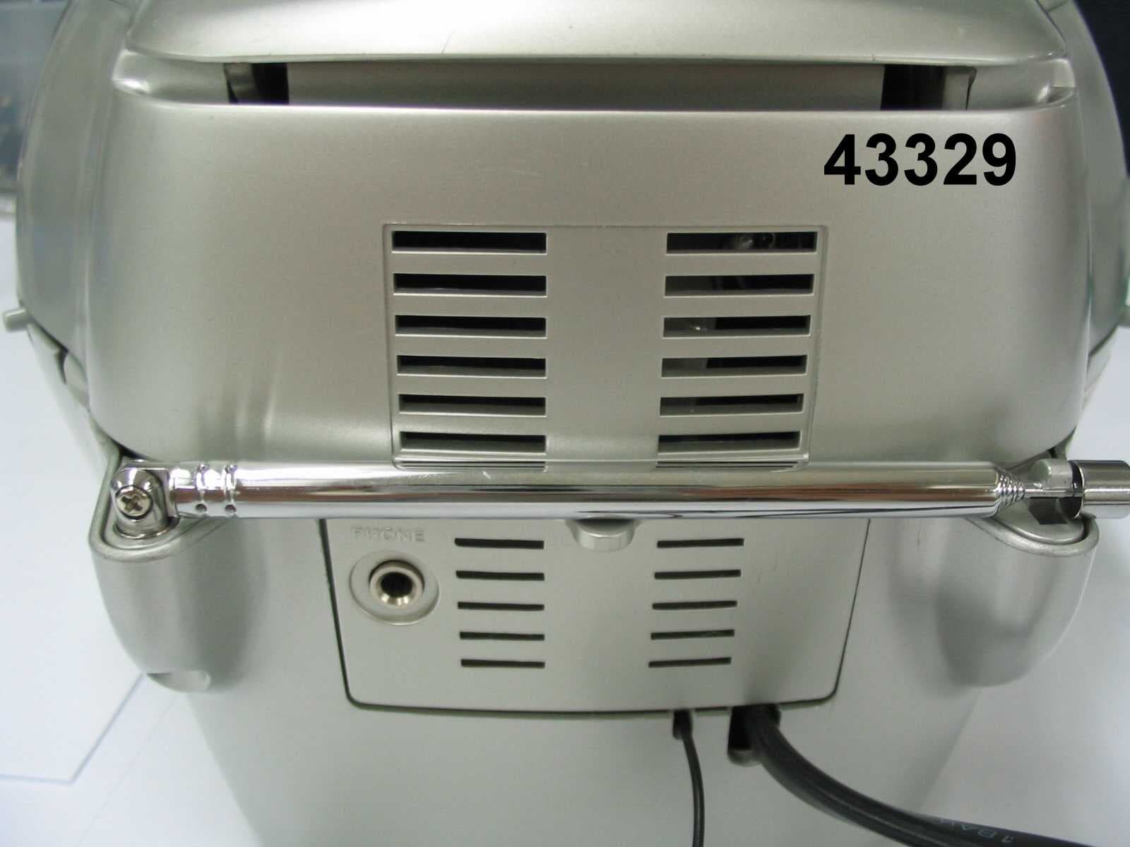
CKW2000 Circuit Description of Weather Band Radio 1. Weather Band Receiver. Weather band signal passed form WB antenna into band pass filter (L/C network C40.C01~CO4 / L01~L03) and RF amplifier Q01 to amplify it. Local oscillator frequency is derived from IC02/Q04/D01 by main coil / capacitors to generated frequency 141.0Mhz to 141.15Mhz. So the channel selection from 162.4MHz to 162.55MHz depend on MCU IC301 to control IC02. 2 nd fixed ref oscillator frequency 20.95MHz by XTAL01. Both Weather band signal and local oscillation frequency will feed to the mixer IC01,FLT03,DIS01 to generate 455KHz IF signal. 455KHz IF signal will be amplifier and feed to narrow band FM demodulated by modulator IC01 and than pass audio signal to audio amplifier IC202 and output to speaker. 2. Alarm Hazardous alert Bell Sounds generator. S.A.M.E decoded by IC204, decoded information controlled by MCU IC301. MCU IC301 will generate hurry Bell or Bell sounds or hazardous alert signal pass to buffer amplifier Q305 than through audio amplifier IC202 and output to speaker . 3. Real time clock and alarm clock and S.A.M.E Display. MCU IC301 has 32.768KHz(Y301) crystal oscillator generate real time clock. It also contents LCD driver to shows real time clock, alarm time and S.A.M.E information onto LCD display Antenna and Ground Circuitry: This unit makes use of an external flexible 12 centimeter long antenna. The antenna is inductively coupled. The unit relies on the ground tract of the printed circuit board. No external ground is provided. *NOTE: This product have two power supply, AC adaptor DC is for main unit and battery is backup for main AC shunt down , so it has battery low detect circuit whichQ214 and Q213 for 6V (AAAx4) . Weather band receiver will switch on/off and tone sound control by MCU IC301/Q307. MCU IC301 also control Q302,Q303 and Q304 for alert LED on/off while S.A.M.E. information are in.
Test Report
F F C C C C - - T T E E S S T T R R E E P P O O R R T T REPORT NO.: 47279 FCC – Test Report No. 47279 Date: 2007-03-24 Page 2 of 20 FCC listed testlab acc. to Section 2.948 of the FCC - Rules in compliance with the requirements of ANSI C63.4 - 2003 Product : AM/FM Weather Alarm Clock Radio with SAME Product Class : Communication Receiver (Super Hetrodyne) Brand Name : Emerson Research Model : CKW2000, CKW2500 Importer / Manufacturer : LASCO INDUSTRIES LIMITED FCC – Test Report No. 47279 Date: 2007-03-24 Page 3 of 20 TABLE OF CONTENTS 1. Cover sheet 2. Introduction 3. Table of Contents 4. Laboratory Report 5. Test Location and Summary of Test Results 6. Test Equipment List 7. Radiated Emission Test Setup 8. Conducted Emission Test Setup 9. Test Procedure 10. Test Results 11-19. Measurement Data 20. Photo of sample FCC – Test Report No. 47279 Date: 2007-03-24 Page 5 of 20 Test Location International Electrical Certification Centre Ltd. Unit 602-605, 31 Lok Yip Road, On Lok Tsuen, Fanling, N.T., Hong Kong Tel : +852 23052570 Fax : +852 27564480 Email : [email protected] Summary of Test Results Radiated Emission: Test result: O.K. Test data: See attached data sheet Conducted Emission: Test result: O.K. Test data: See attached data sheet FCC – Test Report No. 47279 Date: 2007-03-24 Page 6 of 20 TEST EQUIPMENT LIST Equipment Manufacturer Model Serial No. Last Calibration Date Next Calibration Date Test Receiver Rohde & Schwarz ESVP 860688/022 14/11/2006 13/11/2007 Test Receiver Rohde & Schwarz ESHS 30 839667/002 14/11/2006 13/11/2007 Artificial Mains Network (LISN) Schwarzbeck NSLK 8127 8127312 20/12/2006 19/12/2007 Antenna Schaffner CBL6111C 2791 25/05/2005 24/05/2008 Antenna Mast System Schwarzbeck AM9104 -- -- -- Turntable with Controller Drehtisch DT312 -- -- -- FCC – Test Report No. 47279 Date: 2007-03-24 Page 7 of 20 Radiated Emission Test Setup (3 m diatance) 3 m Antenna Antenna mask h = 1 m - 4 m Mains 0.8 m Filter Filter Mains Ground Plane Field Strength Meter EUT (on turntable) FCC – Test Report No. 47279 Date: 2007-03-24 Page 8 of 20 Conducted Emission Test Setup FCC – Test Report No. 47279 Date: 2007-03-24 Page 9 of 20 Test Procedure Radiated Emission : The EUT was tested according to ANSI 63.4-2003 for the requirements of FCC Part 15 Subpart B Section 15.109. During the test, the sample was placed on a turn table and operated under various modes with supply at rated AC voltage (i.e AC120V 60Hz). The sample was fitted with the provided antenna wire (length = 0.48 m) which was fully extended during the test. In addition, the fixed telescopic antenna was also fully extented during the test. The table is 0.8 meter above the reference ground plane on the Open Aera Test Site and can rotate 360 degrees to determine the position of the maximum emission level. A broad-band antenna for the frequency range 30 - 1000 MHz, connected with 10 meters coaxial cable to the test receiver was used for measurement. The antenna is capable of measuring both horizontal and vertical polarizations. The antenna was raised from 1 to 4 meters to find out the maximum emission level from the EUT. An initial pre-scan was performed to find out the maximum emission level of the sample placed at 3 orthogonal planes. Final measurement (30 MHz –1000 MHz) was then performed to record the data for the emissions under worst-case condition for combination of the antenna orientation / height and turn table position. Note : The Open Aera Test Site located at IECC was placed on file with the FCC Pursuant to Section 2.948 of the FCC Rules (FCC Registration No. : 97774). Conducted Emission : The EUT was tested according to ANSI 63.4-2003 for the requirements of FCC Part 15 Subpart B Section 15.107. During the test, the sample was placed on a wooden table and operated under various modes with supply at rated AC voltage (i.e AC120V 60Hz) via the LISN. The sample was fitted with the provided antenna wire (length = 0.48 m) which was fully extended during the test. In addition, the fixed telescopic antenna was also fully extented during the test. The table is 0.8 meter above the floor. The LISN which was connected to the test receiver for conducted emission measurement (150kHz – 30MHz). FCC – Test Report No. 47279 Date: 2007-03-24 Page 10 of 20 Test Results Radiated Emission : Test Requirement: FCC Part 15 Subpart B Section 15.109 Test Method: ANSI C63.4 : 2003 Deviations from Standard Test Method: Nil Frequency Range: 30MHz – 1000MHz Measurement Distance: 3 m Class: Class B Detector: Quasi-Peak Refer to page 11- 15 for measurement data. Conducted Emission : Test Requirement: FCC Part 15 Subpart B Section 15.107 Test Method: ANSI C63.4 : 2003 Deviations from Standard Test Method: Nil Frequency Range: 150kHz – 30MHz Class: Class B Detector: Quasi-Peak / Average Refer to page 16 - 19 for measurement data. 141U1Date : 2007-03-24 Page 11 of 20 Radiated Emission According: FCC Part 15 Subpart B (15.109) IECC Ref:47279 Model:CKW2000 Test Equipment Applicant:LASCO INDUSTRIES LIMITEDReceiver: ESVP Rohde & Schwarz Antenna: Schaffner CBL6111C Ser.Nr.: -- Oper. Mode:FM Mode InterFreq:10.7MHz Receiving - frequency (MHz) Oscillator- frequency (MHz) Har- monics Reading dBμV Polari- zation Correction Factor (dB) Test Result dB(μV/m) Limit dB(μV/m) 89.8201.0127.0H8.635.643.5 402.02<16.0H16.9<32.946.0 603.03<16.0H20.9<36.946.0 804.04<16.0H24.0<40.046.0 98.3218.0132.0H8.740.746.0 436.02<16.0H17.8<33.846.0 654.03<16.0H21.6<37.646.0 872.04<16.0H25.3<41.346.0 108.0237.4129.0H11.040.046.0 474.82<16.0H18.7<34.746.0 712.23<16.0H22.9<38.946.0 949.64<16.0H27.6<43.646.0 The measurement results indicate that the test unit meets the FCC requirements Note : The above results were the worse case results with the sample positioned in all 3 axis during the test Operator : KS 141U1Date : 2007-03-24 Page 12 of 20 Radiated Emission According: FCC Part 15 Subpart B (15.109) IECC Ref:47279 Model:CKW2000 Test Equipment Applicant:LASCO INDUSTRIES LIMITEDReceiver: ESVP Ro…
Text truncated - open the document above for the full version.
Contact Information
Applicant
Frankie Lee
852-2790-3032Fax: 852-2790-3162
Technical Contact
International Electrocal Certification Centre LtdElvin K B Lau
[email protected]852 2305 2570
Unit 602-605, 6/F, 31 Lok Yip Road · Fan ling · Taiwan
Non-Technical Contact
International Electrocal Certification Centre LtdPenny Kong
[email protected]852 2305 2570
Test Firm
SGS IECC LimitedJeffery Chen
Technical Specifications
| # | Rule Parts | Frequency Range | Power Output |
|---|---|---|---|
| 1 | 15B | 162.4 MHz - 162.55 MHz | - |
Other Applications from Lasco Industries Limited
MU4JCR535WN
Dec 14, 2005AM/FM CD CLOCK RADIO WITH WEATHER BAND
Equipment Class
CXX - Communications Rcvr for use w/ licensed Tx and CBs
MU4JCR535W
Apr 18, 2005WEATHER ALERT RADIO W/ AM/FM/CD PLAYER
Equipment Class
CXX - Communications Rcvr for use w/ licensed Tx and CBs
MU4RP6249
Apr 14, 2005WEATHER BAND AM/FM/TV BAND RADIO
Equipment Class
CXX - Communications Rcvr for use w/ licensed Tx and CBs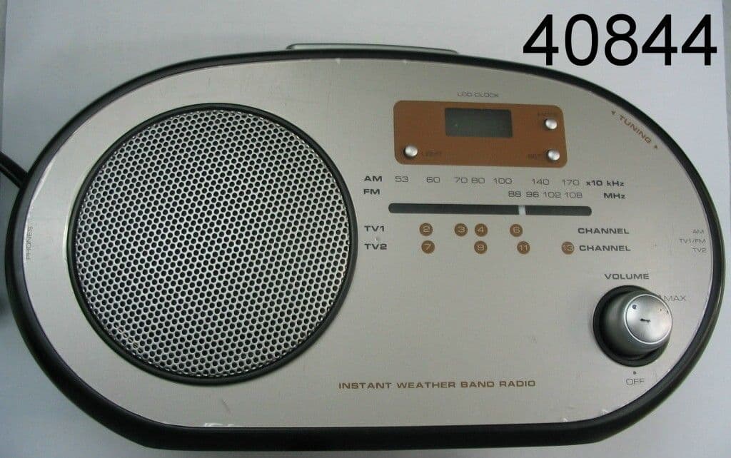
MU4RP1103
Feb 06, 2005AM/FM WEATHER TV BAND RADIO
Equipment Class
CXX - Communications Rcvr for use w/ licensed Tx and CBs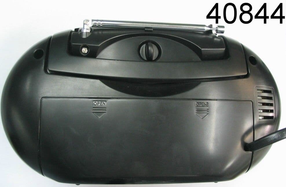
MU4PR1103
Feb 03, 2005AM/FM WEATHER TV BAND RADIO
Equipment Class
CXX - Communications Rcvr for use w/ licensed Tx and CBs