MVADH100-001TTransmitter of RF Digital Headphone System
Uni-Art Precise Products Ltd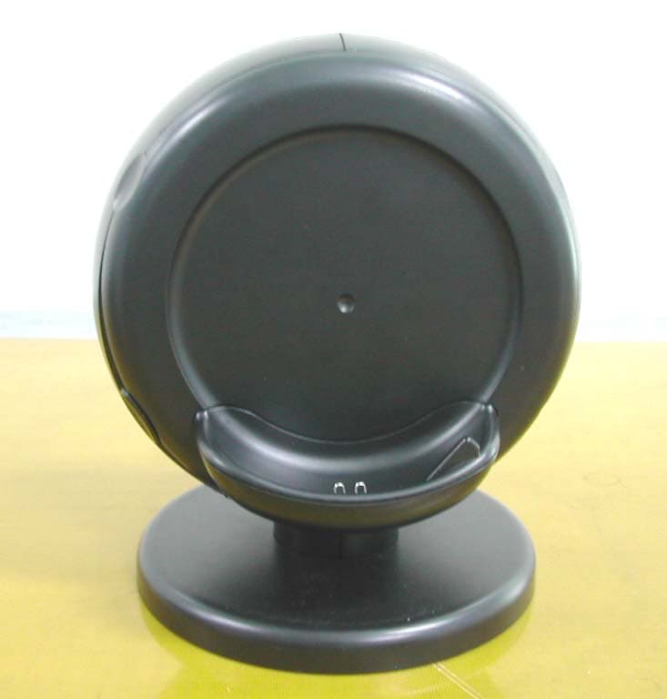
Click to zoom
Application Details
- Equipment Class
- DSS - Part 15 Spread Spectrum Transmitter
- Date of Grant
- Apr 20, 2005
- Application Purpose
- Original Equipment
- Date of Application
- Apr 20, 2005
- Equipment Note
- Transmitter of RF Digital Headphone System
- Frequency Range
- 2404.35000000 - 2480.16000000
- Company
- Uni-Art Precise Products Ltd
- Country
- Hong Kong
Documents & Files
Document Text
Text extracted from the exhibit documents filed with the FCC. Open a document above to read the original.
Users Manual
` DH100 2.4GHz Digital Wireless Headphone User’s Manual Please read before using the equipment P. 1 INTRODUCTION This 2.4GHz Digital Wireless Headphone uses latest digital wireless technology that enables you to enjoy music and TV sound anywhere inside your home. Simply connect the transmitter to a desired audio source: DVD player, CD player, TV set, VCR or Hi-Fi system. Without complicated wiring and installation with your Audio/Video equipments and rear channel amplifier, the system enables you to enjoy thrilling, lifelike sound in minutes. FEATURES 1. Purely 2.4GHz Digital UHF Technology. 2. Electronic Volume Control. 3. Low Power Indicator Alert. 4. High Power 3 x NiMh Batteries 5. Auto Pin Charging Mechanism. 6. Auto On/Off. 7. Auto Shut Off. 8. Muting. 9. Speed charging mechanism. INSTALLATION TRANSMITTER 1. Connect the supplied AC/DC power adapter to an electrical wall outlet. 2. Plug the AC/DC power adapter in the DC jack located on the rear of the transmitter. 3. The rear of the transmitter has one audio cord that can be connected to audio output jack of TV, VCR, Hi-Fi, CD/MP3/VCD/DVD players or to headphone/earphone jack with the connector provided. Plug the adapter in the AC source and connect the audio plug to the audio source. The transmitter will automatically switch on and the red LED will light up when it receives an audio signal. P. 2 HEADPHONE RECEIVER 1. To install or replace the rechargeable batteries, carefully remove the leather padding around the left and right earphone plates out from the cabinets. 2. Insert 2pcs of AAA size rechargeable batteries (supplied in the package) into the right earphone’s battery compartment and 1pc of AAA size rechargeable battery (supplied in the package) into the left earphone’s battery compartment. Make sure the batteries are placed at the right polarity. 3. Cover the leather padding back after inserted the batteries. OPERATION Transmitter 1. Turn on the audio source (TV or audio component) to which the transmitter is connected with. The Signal / Power LED (Red) on the transmitter will light up when it receives the audio signal. Headphone 1. Turn on the headphone by pressing the Power button. The POWER LED (Red) will light up, the green LED will be flashing until signal link between transmitter and receiver is established. 2. Gently place the headphone on your head and adjust for comfort. To obtain the desired sound level, you can adjust the volume control on the headphone. If interference or poor signal reception occurs, the headphone will perform the muting function automatically, and it will search the best channel. The green LED will be flashing when it is searching for the best channel. 3. Charging the batteries a) Turn OFF the headphone first. b) Place the headphone on the transmitter charging cradle. The charging process begins automatically, and the green LED will light up when the charging contacts of transmitter and headphone are made successfully. When the charging process is completed, the green LED will turn off. c) With the smart speedy charging function, the headphone could be fully charged within 4-5 hours. If the headphone is not in use, please place it back to the transmitter charging cradle. P. 3 Important: 1. Switching Off a) For protection of the transmitter and power saving, the transmitter will switches off automatically if there is no audio source signal for 3 minutes. If the audio source signal returns, the transmitter will automatically switches back on. Then, power on the headphone again. b) The headphone will switch off automatically if there is no signal from the transmitter for 2 minutes. 2. Make sure the headphone is turned off when charging is in process. 3. Only use the included rechargeable AAA batteries. When the headphone is not in use, turn OFF the power to avoid damaging the batteries. 4. To ensure a long service life, fully charge the batteries before using the headphone for the first time. The initial charge takes 12 hours to complete. Ensure the charging socket located on the right earphone connects securely with the charge prongs on the transmitter cradle. TROUBLE SHOOTING NO SOUND - Ensure the AC/DC adapter is fully inserted into the AC outlet and the power connection input on the transmitter. - Ensure the headphone is switch ON. - Headphone battery charge level may be too low, recharge the batteries fully. - Ensure the TV or the connected audio device is switched ON. - The volume of headphone may be too low, adjust the volume to a moderate level. DISTORTION - Ensure the volume level of headphone is set to an approximate level. - The headphone is too far from the transmitter, move it closer. - The audio signal input level is too low. Increase the volume of the audio source. P. 4 TECHNICAL SPECIFICATIONS Transmission Mode : UHF stereo Carrier Frequency : 2.4GHz Digital Operation Voltage : Transmitter, DC 9V 400mA Headphone, 3 x AAA size Rechargeable NiMh batteries (included) Frequency Response : 30Hz – 24KHz Distortion : 0.4% S/N Ratio : 80dB Operation Distance : Up to 200 feet WARNING : Changes or modifications not expressly approved by the party responsible for compliance could void the user’s authority to operate the equipment. Operation is subject to the following two conditions: (1) this device may not cause interference, and (2) this device must accept any interference, including interference that may cause undesired operation of the device. This device must be used with the AC/DC adaptor supplied in the package. The antenna(s) used for the device must not be co-located or operating in conjunction with any other antenna or transmitter. The antenna(s) used for this transmitter must be installed to provide a separation distance of at least 20 cm from all persons and must not be co-located or operating in conjunction with any other antenna or transmitter
Cover Letter(s)
1 Helen Zhao Subject:FW: Uni Art Precise Products Ltd, FCC ID: MVADH100-001T , Assessment NO.: AN04T4424, Notice#1 -----Original Message----- From: Yu Xinlu Sent: Thursday, March 24, 2005 4:42 PM To: Helen Zhao Subject: Re: Uni Art Precise Products Ltd, FCC ID: MVADH100-001T , Assessment NO.: AN04T4424, Notice#1 Dear Helen, The following is our reply for the captioned project: Question #1: Please resubmit a complete test report. The report in the filing has only 20 pages. Answer: I resubmitted a complete test report to your website. Question #2: The user manual does not contain RF exposure statement. The possible statement would be: "The antenna(s) used for the device must not be co-located or operating in conjunction with any other antenna or transmitter." Answer: Please see the revised user manual. Question #3: Please verify whether this certification covers both DH100 and HP990. If so please revise your test report to include two models, and revise attestation statement to indicate that PCB, Schematics, BOM are exactly the same, only cosmetic change for marketing purpose. Answer: We confirm that the certification covers only DH100. See the attached test report. Question #4: If the answer to #3 is Yes, please note the internal Photos you sent me this time are slight different from the ones in your original filing. It seems the PCB size and shape is different. Please indicate clearly which ones are for DH100, which ones are for HP990. Please do not send individual image files to me, please convert it into a complete pdf file. Please also remove the metal shield and retake pictures. Answer: We confirm that the certification covers only DH100. See the attached test report. Question #5: If the answer to #3 is Yes, please provide a complete pdf or word file for all the external photos, please remove headphones as it is a receiver, not the transmitter in the filing. Please indicate clearly which ones are for DH100, which ones are for HP990. Please include picture of AC/DC adaptor, please clearly show whether any suppression compoments (e.g. ferrite core) is used. Answer: Same as the #4. Question #6: Please include FCC ID label location information on the FCC ID label format. Answer:Please see the document uploaded to your website. 2 Question #7: Please send all the attachments related to this application in your return email, please do not include other documents that not related to this application, never put the documents for two applications together. Answer:OK New question #8: This device has 15 channels in transmission mode. But section 4.2 of the test report shows 13 channels only. Please provide the data for the other two channels, please update frequency separation test table accordingly. Answer: Please see the revised test report. New question #9: Section 4.6 of the test report only reports the measurement of middle channel. Please note you need to always report measurement at low, middle and high channels. Please add data for low and high channels. Answer: Please see the revised test report. New question #10: Section 4.8 of the test report does not show the measurement at Low, middle and high channels. Actually the test report does not clearly indicate the channel. Please provide measurement at L, M, H channels. Answer: Please see the revised test report. New question #11: You claim this is a frequency hopping system, as described in Section 15.247(a)(1). The specific requirements in Section 15.247(a)(1) are: 1) A minimum channel separation. 2)Pseudo-random hop sequence. 3) Equal use of each frequency. 4) Receiver matching bandwidth and Synchronization. Please provide detailed operational description to address these requirements. For your quick reference, here I provide you FCC guideline. Pseudorandom Frequency Hopping Sequence Describe how the hopping sequence is generated. Provide an example of the hopping sequence channels, in order to demonstrate that the sequence meets the requirement specified in the definition of a frequency hopping spread spectrum system, found in Section 2.1. Equal Hopping Frequency Use Describe how each individual EUT meets the requirement that each of its hopping channels is used equally on average (e.g., that each new transmission event begins on the next channel in the hopping sequence after the final channel used in the previous transmission event). System Receiver Input Bandwidth Describe how the associated receiver(s) complies with the requirement that its input bandwidth (either RF or IF) matches the bandwidth of the transmitted signal. System Receiver Hopping Capability Describe how the associated receiver(s) has the ability to shift frequencies in synchronization with the transmitted signals. Answer: 3 1) A minimum channel separation. The minimum Channel Separation is 2 MHz. 2) Pseudo-random hop sequence. It’s an adaptive frequency hopping device. The Pseudo Random Sequence is generated according to the Best Channel Table. Firstly, the transmitter created a Best Channel Table and Bad Channel Table based on the channel’s SNR. The better channel is ahead in the tables. And the Best Channel Table includes 15 channel sequence number. Secondly, after link succeed the transmitter informed the receive device the Best Channel Table. Finally, both transmitter and receive device hop frequency according the same table. If some channel became too bad to communication, the transmitter will update the Best Channel Table and Bad Channel Table. 3) Equal use of each frequency. Each transmission on every channel is the same(about 5.33 milliseconds), we use every channel equally, which is in the Best Channel Table. Each new transmission event begins on the following channel and after final channel used in the previous transmission event. 4) Receiver matching bandwidth and Synchronization. The transmitter continuously hopping in the same sequence defined by the Best Channel Table as described above. When the transmitter transmits in the frequency that the receiver …
Text truncated - open the document above for the full version.
External Photos
Outlook of the Transmitter Front View of the Transmitter Rear View of the Transmitter Side View of the Transmitter
ID Label/Location Info
Nameplate and FCC ID FCC label location
Internal Photos
Structure of internal wires: Internal Structure of the Transmitter Top View of the Transmitter’s Inner Circuit Bottom View of the Transmitter’s Inner Circuit Top View of AC/DC Adaptor’s Inner Circuit Bottom View of AC/DC Adaptor’s Inner Circuit
Test Report
1 Helen Zhao Subject:FW: Uni Art Precise Products Ltd, FCC ID: MVADH100-001T , Assessment NO.: AN04T4424, Notice#1 -----Original Message----- From: Yu Xinlu Sent: Thursday, March 24, 2005 4:42 PM To: Helen Zhao Subject: Re: Uni Art Precise Products Ltd, FCC ID: MVADH100-001T , Assessment NO.: AN04T4424, Notice#1 Dear Helen, The following is our reply for the captioned project: Question #1: Please resubmit a complete test report. The report in the filing has only 20 pages. Answer: I resubmitted a complete test report to your website. Question #2: The user manual does not contain RF exposure statement. The possible statement would be: "The antenna(s) used for the device must not be co-located or operating in conjunction with any other antenna or transmitter." Answer: Please see the revised user manual. Question #3: Please verify whether this certification covers both DH100 and HP990. If so please revise your test report to include two models, and revise attestation statement to indicate that PCB, Schematics, BOM are exactly the same, only cosmetic change for marketing purpose. Answer: We confirm that the certification covers only DH100. See the attached test report. Question #4: If the answer to #3 is Yes, please note the internal Photos you sent me this time are slight different from the ones in your original filing. It seems the PCB size and shape is different. Please indicate clearly which ones are for DH100, which ones are for HP990. Please do not send individual image files to me, please convert it into a complete pdf file. Please also remove the metal shield and retake pictures. Answer: We confirm that the certification covers only DH100. See the attached test report. Question #5: If the answer to #3 is Yes, please provide a complete pdf or word file for all the external photos, please remove headphones as it is a receiver, not the transmitter in the filing. Please indicate clearly which ones are for DH100, which ones are for HP990. Please include picture of AC/DC adaptor, please clearly show whether any suppression compoments (e.g. ferrite core) is used. Answer: Same as the #4. Question #6: Please include FCC ID label location information on the FCC ID label format. Answer:Please see the document uploaded to your website. 2 Question #7: Please send all the attachments related to this application in your return email, please do not include other documents that not related to this application, never put the documents for two applications together. Answer:OK New question #8: This device has 15 channels in transmission mode. But section 4.2 of the test report shows 13 channels only. Please provide the data for the other two channels, please update frequency separation test table accordingly. Answer: Please see the revised test report. New question #9: Section 4.6 of the test report only reports the measurement of middle channel. Please note you need to always report measurement at low, middle and high channels. Please add data for low and high channels. Answer: Please see the revised test report. New question #10: Section 4.8 of the test report does not show the measurement at Low, middle and high channels. Actually the test report does not clearly indicate the channel. Please provide measurement at L, M, H channels. Answer: Please see the revised test report. New question #11: You claim this is a frequency hopping system, as described in Section 15.247(a)(1). The specific requirements in Section 15.247(a)(1) are: 1) A minimum channel separation. 2)Pseudo-random hop sequence. 3) Equal use of each frequency. 4) Receiver matching bandwidth and Synchronization. Please provide detailed operational description to address these requirements. For your quick reference, here I provide you FCC guideline. Pseudorandom Frequency Hopping Sequence Describe how the hopping sequence is generated. Provide an example of the hopping sequence channels, in order to demonstrate that the sequence meets the requirement specified in the definition of a frequency hopping spread spectrum system, found in Section 2.1. Equal Hopping Frequency Use Describe how each individual EUT meets the requirement that each of its hopping channels is used equally on average (e.g., that each new transmission event begins on the next channel in the hopping sequence after the final channel used in the previous transmission event). System Receiver Input Bandwidth Describe how the associated receiver(s) complies with the requirement that its input bandwidth (either RF or IF) matches the bandwidth of the transmitted signal. System Receiver Hopping Capability Describe how the associated receiver(s) has the ability to shift frequencies in synchronization with the transmitted signals. Answer: 3 1) A minimum channel separation. The minimum Channel Separation is 2 MHz. 2) Pseudo-random hop sequence. It’s an adaptive frequency hopping device. The Pseudo Random Sequence is generated according to the Best Channel Table. Firstly, the transmitter created a Best Channel Table and Bad Channel Table based on the channel’s SNR. The better channel is ahead in the tables. And the Best Channel Table includes 15 channel sequence number. Secondly, after link succeed the transmitter informed the receive device the Best Channel Table. Finally, both transmitter and receive device hop frequency according the same table. If some channel became too bad to communication, the transmitter will update the Best Channel Table and Bad Channel Table. 3) Equal use of each frequency. Each transmission on every channel is the same(about 5.33 milliseconds), we use every channel equally, which is in the Best Channel Table. Each new transmission event begins on the following channel and after final channel used in the previous transmission event. 4) Receiver matching bandwidth and Synchronization. The transmitter continuously hopping in the same sequence defined by the Best Channel Table as described above. When the transmitter transmits in the frequency that the receiver …
Text truncated - open the document above for the full version.
Test Setup Photos
Photograph of the test setup Conducted Emission Measurement of Radiated Emission Spurious Emission (Front view) (Back view) Spurious Emission and other Items (Front view) (Back view)
Contact Information
Applicant
Simon Chan(Marketing Manager)
Test Firm
GTIHEAYang Chunrong
Technical Specifications
| # | Rule Parts | Frequency Range | Power Output |
|---|---|---|---|
| 1 | 15C | 2.40 GHz - 2.48 GHz | 52.80 µW |
Other Applications from Uni-Art Precise Products Ltd

MVADH1001-001T
Aug 19, 20142.4 GHz Digital Headphone (Base)
Equipment Class
DSS - Part 15 Spread Spectrum Transmitter
MVAABH802-AT0-1-N
Jan 02, 2014Bluetooth Headset
Equipment Class
DSS - Part 15 Spread Spectrum Transmitter
MVAHP4592-001R
Dec 17, 2013900MHz Wireless Headphone
Equipment Class
CSR - Scanning Receiver
MVAHP4591-001T
Dec 15, 2013900MHz Wireless Headphone
Equipment Class
DXX - Part 15 Low Power Communication Device Transmitter
MVABH102-AT0-1-N
Dec 05, 2013Bluetooth Headset
Equipment Class
DSS - Part 15 Spread Spectrum Transmitter