MZKADS3000-1ABCTranslating repeater
Air Net Communications Corporation
Click to zoom
Application Details
- Equipment Class
- PCB - PCS Licensed Transmitter
- Date of Grant
- Jan 07, 2001
- Application Purpose
- Original Equipment
- Date of Application
- Jan 07, 2001
- Equipment Note
- Translating repeater
- Frequency Range
- 1850.20000000 - 1909.80000000
- Country
- United States
Documents & Files
Document Text
Text extracted from the exhibit documents filed with the FCC. Open a document above to read the original.
Cover Letter(s)
Communications Corporation November 3, 2000 3950 Dow Road Melbourne, FL 32934 321-984-1900 Re Confidentiality Request for : AdaptaSite TM Translating Repeater FCC ID MZKADS3000-1ABC The reason AirNet requests that photographs showing module interiors and the installation manual to be held confidential is to try to and prevent our competition from gaining access to this data. AirNets’ products represent a significant technological leap from existing state of the art wireless infrastructure and interest from competitors is, understandably, keen. We wish to protect our intellectual property as much as possible. Our customers are under Non-Disclosure agreements with AirNet. This prevents them from distributing photographs of the equipment. Certain components, such as the amplifiers, have their warranty voided if anyone unauthorized removes the cover. This also discourages the user from opening these modules and photographing them. As to the installation manual, only AirNet trained and qualified field-service personnel would typically have access to this data, as we normally are responsible for the installation of our products. The Non-disclosure agreements would also discourage unauthorized distribution of this material by AirNet’s customers. There seems to be some precedence for this type of request. Refer to Nokia application, FCC ID L7KTXU61. This application has the user’s manual and interior photographs removed for confidentiality. This request was also granted on AirNet MZKRE3010-1900. Regards Kenneth Bass (Rahman Amin) Approvals Engineer AirNet Communications Corp. ph: 321-984-1990 x6526 fx: 321-757-0624
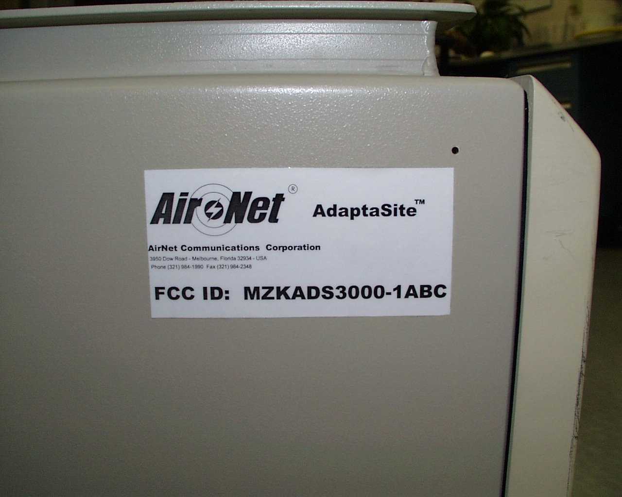
ID Label/Location Info
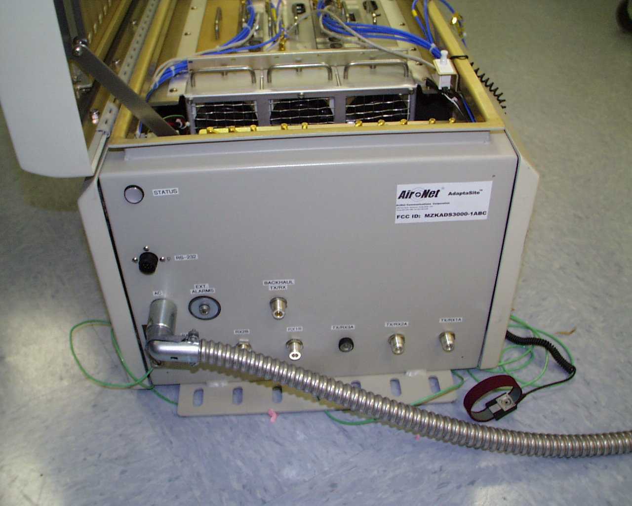
3950 Dow Road - M e l bo u r n e, F l o r i d a 3293 4 - USA Phone (321) 984-1990 Fax (321) 9 84- 23 48 R TX2/RX2A TX3/RX3A RX1B RX2B RX3B RS-232 STATUS AC EXT.ALARMS TX1/RX1A BACKHAUL TX/RX
Operational Description
Kenneth Bass 321-984-1990 x6526 AIRNET Communications Corp. The AdaptaSite TM General Description: The AirNet AdaptaSite Radio (AR) is a translating repeater intended for use in PCS1900 communications. The AR can extend the range of large capacity basestation to remote cells. This means the expensive processing required in the basestation can be centrally located and used to control a larger coverage area. Instead of having to purchase multiple BTS units, a service provider can buy a single BTS and multiple ARRs to cover the same area. The AR uses in-band radio frequency channels to backhaul the traffic in the coverage area to and from the serving BTS. For each AR deployed, four downlink frequencies and Four uplink frequencies are necessary. The first frequencies, the ground frequencies, links the mobile station and the AR. The second set of frequencies are the backhaul frequencies which links the AR to its serving BTS. To the mobile user, an AR appears as a Dual channel basestation. The AR provides Four low noise receive paths for each radio channel. The Receive diversity reception ANT connections helps reduce the Rayleigh Fading, which can destroy communication links. Internal processing selects and retransmits the best of these independent receive paths. Note: the AR does no modulation or demodulation at this time. But Future model will (Therefore it will require Class 2 Change to FCC Part 24 application at later date). Also, 2 different vendors of the power amplifier and modular AC/DC power supply are to be inclusive in the initial submission. The AR hardware is housed in a NEMA-2 enclosure suitable for a wall or a tower. Five antennas are external to the enclosure and are connected by low-loss RF cable. Four of these antennas are dedicated for transmit and receive of the ground frequencies in the AR cell.. The backhaul antenna provides transmit and receive of backhaul frequencies. A block diagram of the AR is shown below. The backhaul antenna receives up to 2 channels from its serving Base station in the frequency range of 1930-1990 MHz. It down-converts these signals to an IF, and then Up-converts based on a different LO and re-transmits the channel to the mobile station at a different frequency in the same band via the diplexed ground antennas. This is the downlink path of the AR. Similarly, each of the four antennae receives a single channel from a mobile station in the frequency range of 1850 to 1910 MHz. Two sets of identical paths down-convert the signals to an IF, where the diversity selection is made. The chosen signal is then up-converted based on a different LO and re-transmitted to the Base Station (BTS).
Parts List/Tune Up Info
1. Circuit Description The following descriptions are included: (1) means for modulation limiting, (2) means for power limiting, (3) means for spurious radiation limiting, (4) means for frequency stabilization. (5) Tune-up procedure, (6) Defined adjustable power levels 1.1. Means for Modulation Limiting Figure 1 illustrates the Adaptasite signal flow when functioning as a repeater between the mobile unit and the broadband RF transceiver (BTS). The GMSK modulated (uplink or downlinkl) RF signal is received at the DAS receive (RX) inputs and downconverted to baseband by RF and digital circuitry. Surface Acoustic Wave (SAW) filters in the receive chain limit the signal bandwidth to the desired frequency range. The analog baseband signal is converted to a digital signal and input to a digital downconverter (DDC). The DDC utilizes a cascaded - integrator – comb (CIC) filter and multiple programmable FIR filters (87 total taps used) to limit the signal bandwidth through the downconversion process. The output signal 3 dB bandwidth (baseband) is 100 kHz with 105 dB rejection at 150 kHz and 170 dB rejection at 400 kHz. The digital signal from the DDC is routed to a digital upconverter (DUC) in preparation for re-broadcast over the uplink or downlink. Distributed filtering (FIR, halfband, and comb) is applied through the x48 interpolation process to maintain a 3 dB bandwidth of 250 kHz on a 10.7 MHz output signal. The TX RF applies additional ceramic filtering (removes clocks, alias, etc) to the 10.7 MHz signal and SAW filtering at the 2nd IF to control the transmitted bandwidth w hile the signal is upconverted to the appropriate GSM frequency band. Figure 1: Modulated Signal Bandwidth Control Downconversion (RF to Baseband) 4-Stage CIC Filter (decimate by 12) FIR Filter (125 tap) Decimate by 2 FPGA FIR Filter (125 tap) Decimate by 2 FIR Filter (63 tap) Digital Downconverter (DDC) FIR Filter (80 tap) Interpolate by 4 Digital Upconverter (DUC) Interpolate by 2 (halfband filter) Interpolate by 6 Comb Filter NCO Mixer DAC (12 bit) Upconversion (Baseband to RF) ADC (12 bit) 1.2. Means for Power Limiting The Digital Adaptasite (DAS) receives and transmits both uplink and downlink signals between the mobile station (MS) and the broadband RF transceiver (BTS). The DAS provides no automatic RF power level control (ALC) on the uplink signal and only minimal ALC on the downlink BCCH signal to counter slow fading due to atmospheric conditions or component temperature variations. Referring to Figure 2, the uplink from the MS is translated to IF, analog to digital converted (ADC), and digitally downconverted (DDC). The digital data is processed (DSP) to determine the received power level (RX_LEV) from the mobile. To maintain complete receive dynamic range, the RX_LEV is used to adjust a digital variable gain amplifier (DVGA) for full scale input to the ADC. The uplink signal is then upconverted to RF and transmitted over the backhaul link to the BRT. During system installation a test signal is used to set the maximum transmit level from the DAS to provide –70 dBm at the BTS (if possible) while remaining compliant with spectral specifications. The digital sine wave output amplitude (FPGA) required to set this –70 dBm level is stored in DAS memory for use during normal operation. The uplink output power of the DAS is +30 dBm (1 watt) nominal . The output amplifier will saturate to limit the antenna input power to +31.5 dBm (1.4 watts) maximum . Signal flow through the dow nlink DAS is identical to the uplink except for the addition of a 56 watt high power amplifier at the output. In this case a sample of the transmit signal is detected and used for closed loop level control on the broadcast control channel (BCCH). The gain of the digital upconverter (DUC) is adjusted to maintain maximum output power of +46 dBm (40 watts) at the antenna input. Detector accuracy is +/- 1 dB over frequency and temperature and DUC gain resolution is < 1 dB . The downlink output power of the DAS is +46 dBm (40 watt) nominal . The output high power amplifier will saturate to limit the antenna input power to +47.5 dBm (56 watts) maximum if level control fails. The BTS controls traffic channel power relative to this maximum level. Figure 2: Simplified Danger Signal Flow Diagram MSMS UL DL TX RX Duplexer UL DL BTS RX TX Duplexer Downconverter DVGA -6 dB to +30 dB 6 dB steps DUC / DAC control UpconverterPA DownconverterUpconverterHPA DVGA DSP / FPGA ADC / DDC DUC / DAC control DSP / FPGA ADC / DDC ALC 1.3. Means for Spurious Radiation Limiting The Digital Adaptasite (DAS) is designed to minimize spurious emissions inside and outside of the selected modulation bandwidth. Careful frequency planning in the up conversion chain minimizes intermodulation (IM) products from the mixer stages. Multiple stages of filtering further attenuates out of band spurious signals generated by mixers and amplifiers. Figure 3 illustrates the DAT transmit (TX) frequency plan and filtering scheme. A modulated 10.7 MHz TX signal is received from the DAT digital upconverter (DUC) and translated to a 125 MHz IF using a double balanced passive mixer and a low side LO at 114.3 MHz. Input bandwidth is constrained with digital filtering in the DUC and a ceramic filter in the RF circuit. The IF is filtered by a surface acoustic wave (SAW) bandpass filter centered at 125 MHz with a 800 kHz 3 dB bandwidth. Out of band rejection for the first SAW is greater than 55 dBc at 13 MHz offset from center out to 450 MHz. An LC image reject filter is also included prior to the second mixer. The signal is then translated to the uplink or downlink TX frequency range with a DB passive mixer and a high side LO from 1975 to 2115 MHz. A SAW filter following the mixer is selected for the proper link frequency. Both filters have a 60 MHz 3 dB bandwidth and greater than 25 dB out of band rejection at 50 MHz offset. Proper impedance control at each mixer port improves VSWR and reduces reflec…
Text truncated - open the document above for the full version.
RF Exposure Info
Intertek Testing Services FCC Part 24 Evaluation of the Adaptasite DAS System For AirNet Communications Corporation FCCID: MZKADS3000-1ABC AirNet Communications Corporation131909 Page 1 of 2 1.0ANSI C95.1 Compliance Table 1.1: ERP Calculations Transmit Maximum ERP Calculation 100’ Coax Omni Antenna Downlink 100’ Coax Dish Antenna Upl i nk Total Power for all Channels (Watts)40.02.0 Maximum Antenna Gain (dBd)10.027.3 Minimum TX Foam Cable Loss, 1-5/8” (dB)1.301.30 Minimum TX Jumpers and Adapter Loss (dB)1.01.0 AdaptaSite Remote Radio EIRP (dBm)55.958.0 AdaptaSite Remote Radio EIRP (Watts)386.31037.2 AdaptaSite Remote Radio ERP (dBm)53.760.1 AdaptaSite Remote Radio ERP (Watts)235.5632.5 The AdaptaSite Remote Radio is capable of using up to 3 channels at a maximum of 40 Watts each. EXAMPLE CALCULATION FOR THE OMNI ANTENNA P is the ma xi mum total power in Watts tra ns mitted b y the a ntenna. CL is the Cable loss in dB. JAL is the loss in dB due to jumpers and adapters. AG is the maximum antenna gain in dBd. ERP( dBm ) = 10 ∙ Log (P ∙ 1000) – CL – JAL + AG ERP( dBm ) = 10 ∙ Log (40 ∙ 1000) – 1.3 – 1.0 + 10 ERP( dBm ) = 53.7 ERP( Watts ) = 10 [{ ERP( dBm ) – 30}/10] ERP( Watts ) = 10 [{ 53.7 – 30 }/ 10 ] ERP( Watts ) = 235.5 EIRP( dBm ) = ERP( dBm ) + 2.1 EIRP( dBm ) = 53.7 + 2.1 EIRP( dBm ) = 55.9 EIRP( Watts ) = 10 [{ EIR P( dBm ) – 30}/10] EIRP( Watts ) = 10 [{ 55.8 – 30}/10] EIRP( Watts ) = 386.3 Intertek Testing Services FCC Part 24 Evaluation of the Adaptasite DAS System For AirNet Communications Corporation FCCID: MZKADS3000-1ABC AirNet Communications Corporation131909 Page 2 of 2 2.0Maximum Permissible Exposure In typical installations, the antenna will be mounted to a tower or above a rooftop by a minimum of 10 meters. Since the total power of all channels is less than 1000W ERP (1640W EIRP), compliance testing with the MPE limits of FCC 96-326 is not required. The limit for Maximum Permissible Exposure (MPE) at the frequency of 1.96 GHz is 6.53 mW/cm 2 . For Occupational/Controlled Exposure using the equation Limit = f/300 per FCC 96-326 and 1.31 mW/cm 2 for General Population/Uncontrolled Exposure using the equation Limit = f/300 per FCC 96-326. The EIRP at 1.96 GHz for the AdaptaSite Remote Radio’s directional antenna is 1037 Watts; the transmitted power is 2 Watts. The conversion from power to power density uses the following equation: PD = P r G/4 π r 2 Where: PD is Power Density (in W/m 2 ); P r is radiated power (in watts); G is the numeric gain of the antenna; and r is the distance (in meters) from the antenna. The conversion from W/m 2 to mW/c m 2 is: mW/cm 2 = W/ m 2 /10 Calculations: The distance, r, is dependant on Occupational/Controlled Exposure or Population/Uncontrolled Exposure. The following table illustrates the power density for the antennas used on the ARR. These antennas are located at the top of the cell site tower. At a distance of r = 10 m from the antenna, the power density is as follows: NOTE: this power density will only be induced on an individual if that individual was physically 10 meters in the main beam of the antenna): Table 2.1: Power density calculations for MPE Uplink PathDownlink Path Antenna Gain (dBi)29.412.1 Numeric gain871.016.2 Rated Power (Watts)240 Pow er Density ( W/ m 2 ) @ 10 m1.390.516 Pow er Density ( mW/c m 2 ) @ 10 m0.140.0516 Minimum distance, in m, for MPE4.612.81 At this power level, an individual would need to be within 5 meters in-line with the main beam of the uplink antenna in order to be at the limit for controlled exposure. This EUT, at 10 meters away from the transmit antennas, is well within the limits for maximum permissible exposure.
Test Report
Intertek Testing Services FCC Part 24 Evaluation of the Adaptasite DAS System For AirNet Communications Corporation FCCID: MZKADS3000-1ABC AirNet Communications Corporation0026476u.doc Page 1 of 22 Test and Measurement Report In support of APPLICATION FOR CERTIFICATION AirNet Communications Corporation Model: Adaptasite Remote Radio FCCID: MZKADS3000-1ABC Intertek Testing Services FCC Part 24 Evaluation of the Adaptasite DAS System For AirNet Communications Corporation FCCID: MZKADS3000-1ABC AirNet Communications Corporation0026476u.doc Page 2 of 22 TABLE OF CONTENTS 1.0Test Lab...............................................................................................................................3 1.1Statement of Certification...................................................................................................................3 1.2Site Description...................................................................................................................................3 2.0General Information............................................................................................................4 2.1Production plans following 2.981 (c).................................................................................................4 2.2Application References following 2.1061..........................................................................................4 2.3Data Submittal Procedure:..................................................................................................................4 2.4 Description of EUT Configuration and Test Setup:..........................................................................4 3.1RF Power output data.........................................................................................................................5 3.2Occupied Bandwidth..........................................................................................................................6 3.3Emissions at edge of Frequency Block...............................................................................................7 3.3.1Downlink....................................................................................................................................7 3.3.2Uplink.........................................................................................................................................7 3.4Antenna Conducted Spurious Emissions..........................................................................................12 3.5Radiated Spurious Emissions............................................................................................................17 3.6Frequency Stability...........................................................................................................................18 4.0Measurement Procedure and Test Equipment...................................................................20 4.1RF Output Power - CFR 47 Part 2.985 (a).......................................................................................21 4.2Occupied Bandwidth - CFR 47 Part 2.989.......................................................................................21 4.3Radiated Spurious - CFR 47 Part 2.993...........................................................................................21 4.4Conducted Spurious Emissions - CFR 47 Part 2.991......................................................................21 4.5Frequency Stability - CFR 47 Part 2.995.........................................................................................22 Intertek Testing Services FCC Part 24 Evaluation of the Adaptasite DAS System For AirNet Communications Corporation FCCID: MZKADS3000-1ABC AirNet Communications Corporation0026476u.doc Page 3 of 22 1.0Test Lab 1.1Statement of Certification The technical data supplied with this application, having been taken under my supervision is hereby duly certified. The following is a statement of my qualifications: 1)BSEE from Auburn University, Alabama 2)Over 5 years of experience in the field of electromagnetic emissions testing I certify that the above application was prepared under my direction and that to the best of my knowledge and belief, the facts set forth in the application and accompanying technical data are true and correct. _________________ David J. Schramm Position: Technical Supervisor ITS Duluth, GA Date: January 8, 2001 1.2Site Description The semi-anechoic test site and conducted measurement facility used to collect the emission data is located at 1950 Evergreen Blvd, Suite 100, Duluth, Georgia, USA. This test facility and site measurement data have been placed on file with the FCC. Intertek Testing Services FCC Part 24 Evaluation of the Adaptasite DAS System For AirNet Communications Corporation FCCID: MZKADS3000-1ABC AirNet Communications Corporation0026476u.doc Page 4 of 22 2.0General Information 2.1Production plans following 2.981 (c) Quantity Production of this device is planned. 2.2Application References following 2.1061 Reference is made to the following: 1. PCS1900 Air Interface Specification - JCT (AIR)/94.08.04-231R4 2. Similar application: FCCID: MZKADS3000-1ABC 2.3Data Submittal Procedure: Data is supplied according to Part 2, Sub-part J of CFR 47. 2.4 Description of EUT Configuration and Test Setup: The EUT can be configured as either a single capacity (1A), double capacity (1B), or triple capacity (1C) system. Based upon the internal RF pluming and similarities between configurations The configuration selected for testing was the 1B (Bi-Sectored) Configuration . This configuration represents the “Worst Case” configuration and allows for variants of vendors for duplexer and triplexer filters, combiners, and amplifiers as shown below: TRP 1 DCI 0 TRP 0 CMB DCI 1 DUP 0 RFS 0 DUP 1 DCI 3 DCI 2 GROUND 1 GROUND 1 GROUND 2 GROUND 2 DAT 1 2W UPLINK 1 DAT 3 2W UPLINK 2 DOWNLINK 2 56W DAT 2 DAT 0 56W DOWNLINK 1 BACKHAUL MASTER Intertek Testing S…
Text truncated - open the document above for the full version.
Test Report
A Offset 34.3 dB LVL Ref 30 dBmAtt 30 dB Center 1.8704 GHzSpan 4 MHz400 kHz/ RBW 10 kHz VBW 30 kHz * SWT 40 ms 1 PK VIEW PRN -70 -60 -50 -40 -30 -20 -10 0 10 20 30 Date: 22.MAR.2001 23:17:12 Intermodulation Test results with CW signal input into Rx A and Rx B Combined backhaul output at band edge with 3 rd order IMD.
Test Report
A Offset 34.3 dB LVL Ref 30 dBmAtt 30 dB Center 1.8704 GHzSpan 4 MHz400 kHz/ RBW 3 kHz * VBW 3 kHz * SWT 900 ms 1 PK MAXH PRN -70 -60 -50 -40 -30 -20 -10 0 10 20 30 Date: 22.MAR.2001 23:23:06 Intermodulation Test results with GMSK signal input into Rx A and Rx B Combined backhaul output at band edge with 3 rd order IMD.
Test Report
1/2W Backhaul RF output 40W Downlink Tx/Rx A outputs and diversity Rx inputs Figure 14A - (AdaptaSite) 1B Test Configuration Intermodulation Distortion Setup The EUT was tested with two CW and GMSK signals provided at the ground/mobile Uplink ant inputs. The B/H frequencies at the combiner were set to the edge of the PCS B-Block and intermod products were measured for leakage into adjacent blocks. (Note: in the backhaul-to-ground transmit path, carriers are not combined and thus no IMD products are produced). AC pwr DAT 0 DAT 1 DAT 2 DAT 3 Tx/Rx A Rx DI A AIRSITE Tx/Rx B Rx DI B B/H Tx/Rx Ser #1 Ser #2 PC Ser #3 Ser #4 Var iab le AC source CPL ATTN Spec An / FSY/Ches Tri #1 Clear/AML Tri #2 FSY Dup 1 Clearco Dup 0 CMB LOAD / spec An CPL CPL -30 dB -30d B Sig Gen # 1 -30dB -30dB Sig Gen # 2 Or LOAD LOAD / S pec An
Contact Information
Applicant
Steve Cassidy
Technical Contact
Intertek Testing ServicesDavid J Schramm
[email protected](678) 775 2400
1950 Evergreen Blvd · Duluth, Georgia · United States
Non-Technical Contact
Intertek Testing ServicesDavid J Schramm
[email protected](678) 775 2400
Test Firm
Intertek Testing ServicesDavid Schramm
Technical Specifications
| # | Rule Parts | Frequency Range | Power Output | Emission | Tolerance |
|---|---|---|---|---|---|
| 2 | 24E | 1.85 GHz - 1.91 GHz | 2 W | 300KGXW | 0.12 ppm |
Other Applications from Air Net Communications Corporation

MZKBTS4000-850
Apr 15, 2007Broadband Transceiver System
Equipment Class
TNB - Licensed Non-Broadcast Station Transmitter
MZKBTS4000-1900
Apr 01, 2004BTS-4000
Equipment Class
PCB - PCS Licensed TransmitterMZKRE3010-1900
Mar 31, 1999Single Channel Repeater
Equipment Class
PCB - PCS Licensed Transmitter
MZKBPU3000-1900
Mar 24, 1999PCB - PCS Licensed Transmitter
Equipment Class
PCB - PCS Licensed TransmitterMZKBPU2000-1900
Jan 04, 1998The listed output power is the maximum output power of the device. Output level per channel is 333 uW, with up to 12 channeds available.
Equipment Class
PCB - PCS Licensed Transmitter