N3E74047long range walkie talkie; Model: 74047
Wild Planet Entertainment, Inc.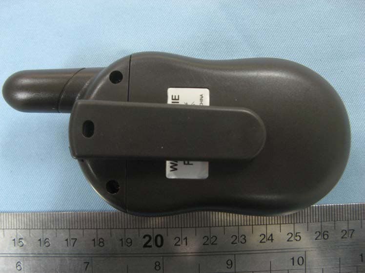
Click to zoom
Application Details
- Equipment Class
- FRF - Part 95 Family Radio Face Held Transmitter
- Date of Grant
- Apr 26, 2011
- Application Purpose
- Original Equipment
- Date of Application
- Apr 26, 2011
- Equipment Note
- long range walkie talkie; Model: 74047
- Frequency Range
- 462.56250000 - 467.71250000
- Country
- United States
Documents & Files
Document Text
Text extracted from the exhibit documents filed with the FCC. Open a document above to read the original.
Users Manual
operation on GMRS frequencies requires an FCC license, and such operation is subject to additional rules specified in Part 95 including prohibited communications in Section 95.183. For hand held operation, the radio device should be held at least 2.5cm from the user’s face. To maintain compliance with FCC RF exposure requirements, body worn operations are restricted to supply belt clip. The use of accessories that do not satisfy these requirements may not comply with FCC RF exposure requirements and should be avoided. FRS Authorized Bandwidth 12.5kHZ 2.1033(c)(5) FRS Frequency Range: 95.627 1. 462.5625 8. 467.5625 2. 462.5875 9. 467.5875 3. 462.6125 10. 467.6125 4. 462.6375 11. 467.6375 5.462.6625 12. 467.6625 6. 462.6875 13. 467.6875 7. 462.7125 14. 467.7125 MHz GMRS Authorized Bandwidth 20.0kHz 2.1033(c)(5) GMRS Frequency Range: 95.621 15.462.5500 16.462.5750 17.462.6000 18.462.6250 19.462.6500 20.462.6750 21.462.7000 22.462.7250 MHz FCC ID: N3E74047 IMPORTANT REGULATORY INFORMATION This device complies with Part 15 of the FCC Rules: Operation is subject to the following two conditions: 1. This device may not cause harmful interference and 2. This device must accept any interference that is received, including any interference that may cause undesired operation. WARNING: Changes or modifications to this unit not expressly approved by the party responsible for compliance could void the user’s authority to operate the equipment.
Cover Letter(s)
Wild Planet Entertainment.Inc Apr .15,2011 Authorization Letter To whom it may concern: Shannon Bruzelius (Product Integrity Manager),hereby authorize Nicholas Lai to act on our contact person and he is signing for all of documents relating to grantee. Sincerely yours, Applicant’s company name : Wild Planet Entertainment,Inc Applicant’s company address : 225 BUSH STREET 13 TH FLOOR, SAN FRANCISCO.CA 94104,USA Signature Job Title Prouct Integrity Mannager
Cover Letter(s)
Apr.07,2011 Federal Communications Commission 7435 Oakland Mills Road Columbia, MD 21046 Gentlemen: This letter is to comply with Sections 0.457 and 0.459 pertaining to confidential material. Wild Planet Entertainment,Inc would like the following documents regarding this submission for FCC ID: N3E74047 to be kept confidential. 1. Block Diagram 2. Circuit Diagram 3. Pars list The above material contains trade secrets or technical data, which would customarily be guarded from competitors. We do not want these documents to be accessible to the general public. Sincerely, {Signed by Company Counsel or Company Officer}
External Photos
TOP VIEW OF EUT BOTTOM VIEW OF EUT LEFT VIEW OF EUT RIGHT VIEW OF EUT FRONT VIEW OF EUT BACK VIEW OF EUT
ID Label/Location Info
FCC ID Lable Location
ID Label/Location Info
FCC ID Lable Location FCC RF Warning Label
Internal Photos
INTERNAL VIEW OF EUT - 1 INTERNAL VIEW OF EUT - 2 INTERNAL VIEW OF EUT - 3
Operational Description
- 1 - CIRCUIT DESCRIPTION 1. RECEIVER SECTION Radio Frequency signal received by the antenna (ANT1), passing through the Low Pass Filter (L1,L3, C2-C5). The RF signal is then amplified by Low Noise Amplifier Q1 and passes through a Band Pass Filter of L6,C511,522,523,C509. The filtered signal within the range of 462MHz is then mixed with the first local oscillator signal from the Voltage Controlled Oscillator (VCO) circuit (Q11,Q10, D7, L18) through Q3, a portion of VCO signal is then feedback to the PLL IC (IC2) for phase comparison generating a stable RX frequency, the output signal is filtered by FL2 (21.7 MHz) which is the first Intermediate Frequency (IF) and is then amplified by Q4. The IF signal is fed to the discriminator IC1 pin 16 which is then mixed with the second local oscillator supplied by crystal X1 (21.25 MHz) to produced a reduced second IF signal which is then filtered by FL1 (KTM450HTW). Demodulated signal is recovered through correct adjustment of IF tank coil (IFT1) and the internal discriminator circuit of IC1. The recovered Audio signal is outputted at pin 9 of IC1 and then processed through filtering done by Q20, the fully recovered audio signal is then further amplified by Power Amplifier IC101. An audible sound is therefore produce by the speaker SPK1 which can be varied digitally from the CPU pins 29,20,31 and the corresponding series of resistors R4,R16,R66. 2. TRANSMITTER SECTION PTT switch (SW1) when pushed triggers the Transmitter Circuit “ON”, the voice signal generates by the surrounding noise passes through the microphone MIC1 where mechanical to electrical transformation occurs, the electrical transformed signal is then filtered by Q18. The output signal is Modulated by a modulator circuit with a varactor diode D7 and L18. The external components from Q10,Q11 form a VCO Circuit which generates the required oscillating frequency for transmission, a portion of this signal is feedback to the PLL IC2 pin 14 for phase comparison in order to produce a stabilized TX frequency. The modulated signal is then amplified by a Cascaded Amplifier Circuit Q7 and Q8 and again amplified by Q2,Q5 ,Q6 to produce a sufficient Radio Frequency signal emitted by the Antenna (ANT1). 3. CALL TRANSMISSION By pushing the PTT/CALL key, a signal is detected by the CPU (IC105), a CALL data is then produced by the CPU. This data passes through the Low Pass Filter Q18 and modulated by the varactor diode D7 and L18. The signal follows it’s conventional transmission section path through the antenna. - 2 - 4. BATTERY LOW DETECTION Battery Low Detection is controlled by the CPU pin 20 as detected on the LCD 1, however a voltage divider circuit R57 and R64 serve as the stabilize reference voltage for the CPU to process its detection. 5. SQUELCH DETECTION Supported by the linear IC circuit (IC1), a resistor R21 sets the level of detection and Diode D3 acts as a comparator circuit interface with the CPU. 6. POWER SUPPLY Supply voltage of 6 Volts dc is needed to power “ON” the whole circuitry, by four (4) batteries “AAA” size. FREQUENCY CHART CHANNEL FREQUENCY (MHz) 1 462.5625 2 462.5875 3 462.6125 4 462.6375 5 462.6625 6 462.6875 7 462.7125 8 467.5625 9 467.5875 10 467.6125 11 467.6375 12 467.6625 13 467.6875 14 467.7125 15 462.5500 16 462.5750 17 462.6000 18 462.6250 19 462.6500 20 462.6750 21 462.7000 22 462.7250
Test Report
FCC&IC Test Report Report No.: AGC 05C110301F1 TEST NAME : FCC Part 95 FCC ID : N3E74047 IC 3675A‐74047 PRODUCT DESIGNATION : Long range walkie talkie BRAND NAME : N/A TEST MODEL : 74047 CLIENT : Wild Planet Entertainment, Inc DATE OF ISSUE : Mar .31, 201 1 STANDARD(S) : FCC Part 95 Rules IC RSS‐210 Rules Attestation of Global Compliance Co., Ltd. CAUTION: This report shall not be reproduced except in full without the written permission of the test laboratory and shall not be quoted out of context. Report No.: AGC05C110301F1 Page 2 of 42 VERIFICATION OF COMPLIANCE Applicant: Wild Planet Entertainment, Inc 225 BUSH STREET 13 TH FLOOR, SAN FRANCISCO, CA94104, USA Manufacturer: Wild Planet Entertainment, Inc 225 BUSH STREET 13 TH FLOOR, SAN FRANCISCO, CA94104, USA Product Description: Long range walkie talkie Brand Name: -- Model Number: 74047 File Number: AGC05C110301F1 Date of Test: Mar. 26 to Mar. 31, 2011 We hereby certify that: The above equipment was tested by Attestation of Global Compliance Co., Ltd. The data evaluation, test procedures, and equipment configurations shown in this report were made in accordance with the procedures given in ANSI C 63.4:2003 and TIA/EIA 603 and IC RSS-210. The sample tested as described in this report is in compliance with the FCC Rules Part 95 The test results of this report relate only to the tested sample identified in this report. Checked By: Jekey Zhang Mar. 31, 2011 Authorized By Randy He Mar. 31, 2011 Report No.: AGC05C110301F1 Page 3 of 42 TABLE OF CONTENTS 1. GENERAL INFORMATION .............................................................................................. 5 1.1 PRODUCT DESCRIPTION ...................................................................................................................... 5 1.2 RELATED SUBMITTAL(S) / GRANT (S) ................................................................................................ 6 1.3 TEST METHODOLOGY .......................................................................................................................... 6 1.4 TEST FACILITY ....................................................................................................................................... 6 1.5 SPECIAL ACCESSORIES ...................................................................................................................... 6 1.6 EQUIPMENT MODIFICATIONS .............................................................................................................. 6 2. SYSTEM TEST CONFIGURATION ................................................................................. 7 2.1 EUT CONFIGURATION ........................................................................................................................... 7 2.2 EUT EXERCISE ....................................................................................................................................... 7 2.3 CONFIGURATION OF TESTED SYSTEM ............................................................................................ 7 3. SUMMARY OF TEST RESULTS ..................................................................................... 8 4. DESCRIPTION OF TEST FREQUENCY RANGE ........................................................... 9 5. FREQUENCY STABITITY .............................................................................................. 10 5.1 PROVISIONS APPLICABLE ................................................................................................................. 10 5.2 MEASUREMENT PROCEDURE ........................................................................................................... 10 5.3TEST SETUP BLOCK DIAGRAM .......................................................................................................... 11 5.4 TEST EQUIPMENT USED: ................................................................................................................... 11 5.5 TEST RESULT ....................................................................................................................................... 11 6. EMISSION BANDWIDTH ............................................................................................... 15 6.1 PROVISIONS APPLICABLE ................................................................................................................. 15 6.2 MEASUREMENT PROCEDURE ........................................................................................................... 15 6.3 TEST SETUP BLOCK DIAGRAM ......................................................................................................... 15 6.4 MEASUREMENT EQUIPMENT USED: ................................................................................................ 15 7. UNWANTED RADIATION .............................................................................................. 18 7.1 PROVISIONS APPLICABLE ................................................................................................................. 18 7.2 MEASUREMENT PROCEDURE ........................................................................................................... 18 7.3 TEST SETUP BLOCK DIAGRAM ......................................................................................................... 19 7.4 MEASUREMENT EQUIPMENT USED: ................................................................................................ 20 7.5 MEASUREMENT RESULTS: ................................................................................................................ 20 8. MODULATION CHARACTERISTICS ............................................................................ 22 8.1 PROVISIONS APPLICABLE ................................................................................................................. 22 8.2 MEASUREMENT METHOD .................................................................................................................. 22 8.3 MEASU…
Text truncated - open the document above for the full version.
Test Setup Photos
RADIATED TEST SETUP
Contact Information
Applicant
Shannon Bruzelius(Product Integrity Manager)
Test Firm
Attestation of Global Compliance Shenzhen Co. Ltd.Forrest Lei
Technical Specifications
| # | Rule Parts | Frequency Range | Power Output | Emission | Tolerance |
|---|---|---|---|---|---|
| 2 | 95B | 462.5625 MHz - 467.7125 MHz | 380.00 mW | 10K9F3E | 1 ppm |
Other Applications from Wild Planet Entertainment, Inc.
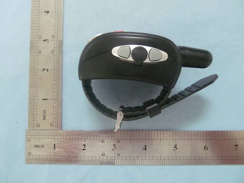
N3EWWWT70489
Nov 22, 2012Wrist Watch Walkie Talkie
Equipment Class
FRF - Part 95 Family Radio Face Held Transmitter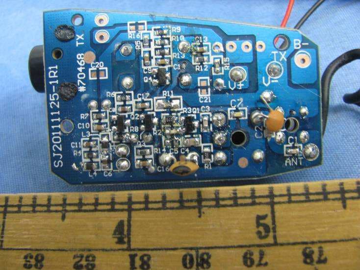
N3EUCLSR70468
May 06, 2012Spy Listener
Equipment Class
DXX - Part 15 Low Power Communication Device Transmitter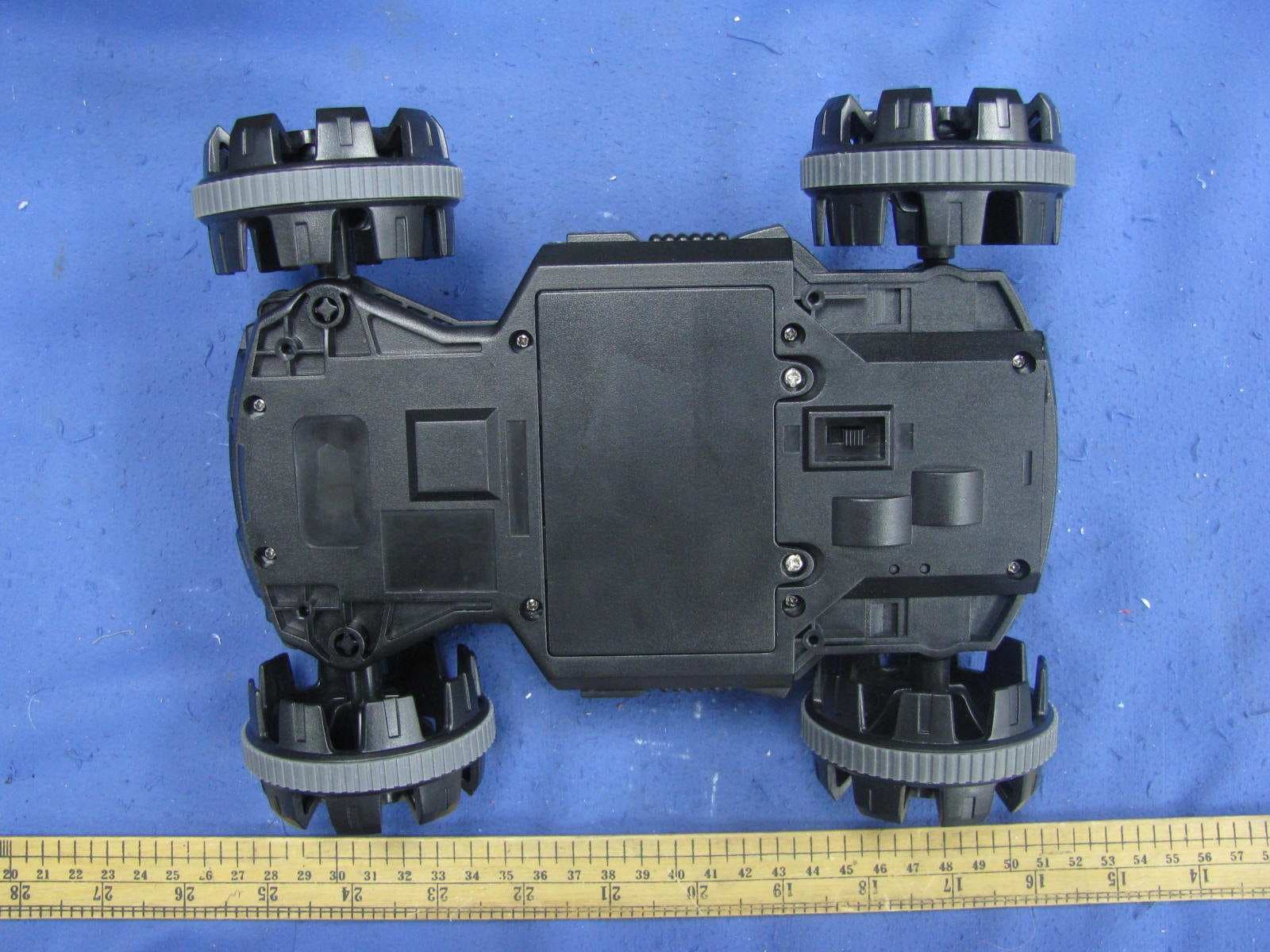
N3ESVC70436TX
Jun 07, 2011Spy Video Car
Equipment Class
DXX - Part 15 Low Power Communication Device Transmitter
N3ESVC70436RX
Jun 07, 2011Spy Video Car
Equipment Class
DXX - Part 15 Low Power Communication Device Transmitter
N3ESPYVIDEOTRAKR2
Jun 19, 2010Spy Video TRAKR
Equipment Class
JBP - Part 15 Class B Computing Device Peripheral