N4TDFR200Dual fixed RFID reader
Phase IV Engineering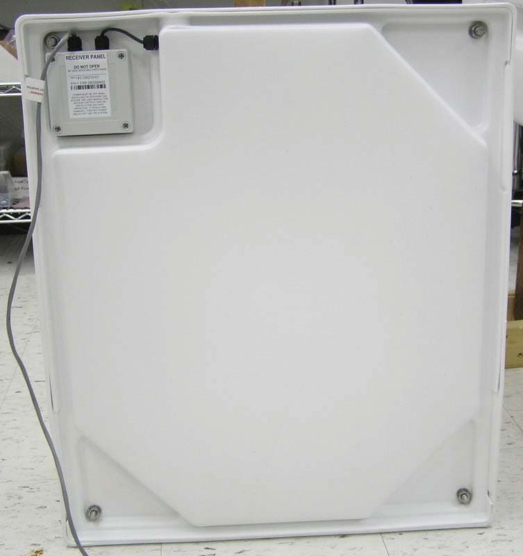
Click to zoom
Application Details
- Equipment Class
- DCD - Part 15 Low Power Transmitter Below 1705 kHz
- Date of Grant
- Jun 13, 2010
- Application Purpose
- Original Equipment
- Date of Application
- Jun 13, 2010
- Equipment Note
- Dual fixed RFID reader
- Frequency Range
- 0.13420000 - 0.13420000
- Company
- Phase IV Engineering
- Country
- United States
Documents & Files
Document Text
Text extracted from the exhibit documents filed with the FCC. Open a document above to read the original.
Users Manual
DVM Systems Dual Fixed Reader Installation Guide and User Manual Document 53-100116-00 Rev 2.1 Page 1 Publis hed: June 9 2010 Important Safety Warnings and Notices Safety Signal Symbols This symbol means that there is a potential hazardous situation. This symbol means that there is a potential electric shock hazard present. Safety Signal Words Warning - The word “Warning” indicates a potentially hazardous situation which, if not avoided, could result in death or serious injury. Dangerous - The word “Dangerous” indicates an imminently hazardous situation which, if not avoided, will result in death or serious injury. Electrical Connection Warnings The installation of DVM Systems’ Dual Fixed Reader must comply with local electrical codes. The safety, usage and maintenance of the electrical wiring installation are the responsibility of the customer. Installation should only be done by someone who has experience with computers and software program installations and who is familiar with computer cabling installation and electrical wiring in agricultural facilities. There are no user serviceable parts inside the Dual Fixed Reader electrical boxes. Electrical connections and parts inside the electrical boxes are to be accessed only by trained, authorized personnel. Warning! We recommend installation be done by a qualified electrician. Dual Fixed Reader will need to be located near 110V outlet. AC input: 120V AC, 50-400 HZ, 250W Control Box Location Only authorized person should open electrical boxes. Installation must comply with local electrical codes. Disconnect all voltage Power source should be 120V or 230/240 V AC Dangerous! Electrical shock can cause severe injury or death. Page 2 High voltag e exists inside control box. Disconnect from breaker before opening lid of control box. FCC Regulatory Statement User Information for this Radio Frequency Device Changes or modifications not expressly approved by the party responsible for compliance could void the user's authority to operate the equipment. This equipment has been tested and found to comply with the limits for a Class A digital device, pursuant to part 15 of the FCC Rules. These limits are designed to provide reasonable protection against harmful interference when the equipment is operated in a commercial environment. This equipment generates, uses, and can radiate radio frequency energy and, if not installed and used in accordance with the instruction manual, may cause harmful interference to radio communications. Operation of this equipment in a residential area is likely to cause harmful interference in which case the user will be required to correct the interference at his own expense. To comply with FCC RF safety guidelines, keep the transmitter at least 2.5 cm from the head or body while the transmitter is operating. “Operation is subject to the following two conditions: (1) this device may not cause interference, and (2) this device must accept any interference, including interference that may cause undesired operation of the device.” Page 3 Intended Use The Dual Fixed Reader is an innovative, wireless temperature sensing and identification system. It is designed to automatically and accurately monitor individual cattle internal temperatures as cattle pass by the reader antenna. The DFR system consists of a reader control box, passive radio-frequency rumen transponder (the Bolus), and driver and receiver panel antennas. Technical Specifications Reader Control Box 20” x 14” x 7” Storage and Operating Environment Temperature range of -40 to 125 °F Humidity of 0-90% RH non-condensing Reader Antennas 28” x 24” x 2.5” Storage and Operating Environment Temperature range of -40 to 125 °F Humidity of 0-90% RH non-condensing Equipment Rating AC input: 105-125V AC, 50-400HZ, 250W Instructions for Use This manual will assist you in getting the system set up and started. It provides instructions on installing the Reader Control Box, setting up the Reader Antennas, and its associated hardware, to operate the system. Electrical Box Mounting The electrical control box needs to be accessible and easy to view. Should be on flat wall, away from water spray Mount with ¼ 20 x 1 inch stainless steel button head socket cap screws and hex socket nut. Mount control box within 6 ft of receive antenna Page 4 Mount the box so that the WiFi antenna is up and the cable grommets are facing down. Panel Mounting Secure the drive and receive antenna panels using bolts that go through the indentations in the panels. Do not drill any other section of the panels as this could cause damage to the electronics within. The panels must be oriented with the panel electrical box on the top left corner, when the panels are viewed from the back. RFID Antenna Wiring Connection Dual fixed reader will not work properly if antenna cables have been shortened. After the DFR panels are mounted, run the cables to the DFR electrical box. The cables must be routed so that the cows have no access to the cables. Run receive and drive antenna cables through separate black plastic grommets the in the bottom of the control box. Do not cut the cables, wind-up any excess cable inside the electrical box. Match labels on antenna cables to label inside control box (receive – R+, and R-. drive – D+ and D-). Secure wire to terminal. Tighten the grommets on the bottom of the electrical box to seal them. Power Source Connection – see warnings on the first page Ground wire must connect to ground lug in control box. The ground lug is marked with a ground symbol. Install per local electrical codes Run AC wire through outdoor ½ inch flexible metallic liquid tight (FMLT) conduit. Attach conduit to right-most metal fitting. AC wires; black = hot, white = neutral, green = ground. Dangerous! Electrical shock can cause severe injury or death. High voltage exists inside control box. Disconnect from breaker before opening lid of control box. Only aut…
Text truncated - open the document above for the full version.
External Photos
Automatic Cow Temperature Monitoring Dual Fixed Reader (DFR200) Component Images May 03, 2010 2820 Wilderness Place, Unit C Boulder, Colorado, 80301 Tel: (303) 443 6611 SHEET 2 OF 14 1. Dual Fixed Reader (DFR200) Figure 1 - DFR200 Driver Panel (Front) SHEET 3 OF 14 Figure 2 - DFR200 Driver Panel (Back) SHEET 4 OF 14 Figure 3 – DFR200 Receiver Panel (Front) SHEET 5 OF 14 Figure 4 - DFR200 Receiver Panel (Back) SHEET 6 OF 14 Figure 5 -DFR200 Panel Side view
Internal Photos
SHEET 7 OF 14 Circuit Board in Receiver Panel with cover on and cover off. There are no components on the back side of the board. The board is mounted with 4 screws. SHEET 8 OF 14 Driver Panel Circuit Board with Cover on and Off There are no components on the back side of the board. The board is mounted with 4 screws inside the box.
Internal Photos
SHEET 9 OF 14 2. Control Box Electrical Control Box with lid closed. Electrical Control Box with lid open. SHEET 10 OF 14 Figure 6 - Control Box Side View The circuit board is held by two screws on the exterior of the box, plus other screws shown in the following photographs. 2.1Control Box Bottom 1)Install one pc of 31-100303-00 Drain with 37-100004-00 Loctite 425. 2)Install one pc of 31-100286-00 Santoprene Plug. SHEET 11 OF 14 3)Apply 37-100009-00 RTV to sealing surface on two pcs of 31-100284-00 Nylon Cordgrips. Install and tighten with Loctite 425 and 31-100285-00 Nylon Locknut – install bottom one first and tighten then install top one. 4)Apply RTV to yellow sealing surface and install one pc of 31-100305-00 Steel Cordgrip with Loctite 425. SHEET 12 OF 14 2.2Plate - Component Installation TORQUE=24 in/lbs (Ingersall Rand set to 12) 1)Install two of 32-100027-19 #10 screws from back of panel with 33-100120-00 LockNut on topside. TORQUE=6 in/lbs ((Ingersall Rand set to 2) Prep: Remove ribs from bottom of 29-100600-00 Terminal Block and install 0.75” x 0.75“ piece of 37-100035-00 PSA to bottom with 3/16” punched hole for screw. 2)Use #1 Driver to install and tighten 29-100600-00 Terminal Block with 37-100019-00 Loctite 222 and one pc of 32-100170-00 #6 x 0.625” Thread-Rolling Screw. Wire entry indicated with arrows above. TORQUE=12 in/lbs (Ingersall Rand set to 6) 3)EMI Filter screws are self-threading. Use #2 Driver to install and tighten 43-100213-00 EMI Filter / 22-100055-00 Switch with Loctite 222 and two pcs of 32-100164-00 #8 x ¼” Thread-Rolling Screw. 4)Install and tighten eight pcs of 34-100064-00 4-40 Standoff with 37-100004-00 Loctite 425 plus 33-100130-00 4-40 Nut w/tooth Washer on backside. TORQUE=16 in/lbs ((Ingersall Rand set to 8) Note: Center 24-100093-00 Power Supply over matching hole pattern in plate. Loosen power supply to align holes if necessary. 5) Use #2 Philips Driver to install and tighten with four pcs of 32-100167-00 8-32 x 0.3125” Screw and 33-100124-00 #8 Lock Washer. SHEET 13 OF 14 2.3Plate into Control Box 1) Place panel assembly in box. 2) Start four screws and #10 lock washers (that come with panel), attach Plate to Control Box. Do not tighten. 3) Install 31-100290-00 Switch Seal on Switch and set switch into cutout in Control Box. Install and tighten Lock Washer (comes with Switch) and 31-100289-00 Boot. Installed Power Switch SHEET 14 OF 14 Control Box - PCB Figure 7 - Control Box - PCB Top View Internal mounting screw holes indicated by colored stickers. Figure 8 -Control Box PCB Bottom View This side is mounted face-down in the electronic enclosure box.
Test Report
Project File: 3188269 Page 1 of 29 Intertek Testing Services NA, Inc. 5541 Central Avenue, Suite 110 Boulder, Colorado 80301 Voice: 303 786 7999 Fax: 303 449 6160 Rev.No 1 EMC EMISSIONS - TEST REPORT (In Part) Test Report No. 3188269DEN-003 Issue Date: August 31, 2009 Model / Serial No. MN: DFR200 /SN: DFR-090006833 Product Type Dual Fixed RFID Reader Client DVM Systems, LCC Manufacturer Phase IV Engineering, Inc. License holder Phase IV Engineering, Inc. 2820 Wilderness Place, Unit C Address Boulder CO 80301 Test Criteria Applied FCC 47 CFR Part 15.209 RSS-210 issue 7 Test Result PASS Test Project Number References 3188269 Total Pages Including Appendices: 28 Title 47 CFR 15: RADIO FREQUENCY DEVICES Subpart C – Intentional Radiators Low-power License-exempt Radio Communication Devices (All Frequency Bands): Category I Equipment Tested By: Michael Spataro Reviewed By : Richard Georgerian REVISION SUMMARY - The following changes have been made to this Report: Rev. Revision Statement Author Revision Date Reviewer Initial Release of Document See above See above A Changed Model Number to DFR200 Michael Spataro 4/28/2010 RGeorgerian This report is for the exclusive use of Intertek's Client and is provided pursuant to the agreement between Intertek and its Client. Intertek's responsibility and liability are limited to the terms and conditions of the agreement. Intertek assumes no liability to any party, other than to the Client in accordance with the agreement, for any loss, expense or damage occasioned by the use of this report. Only the Client is authorized to copy or distribute this report and then only in its entirety. Any use of the Intertek name or one of its marks for the sale or advertisement of the tested material, product or service must first be approved in writing by Intertek. The observations and test results in this report are relevant only to the sample tested. This report by itself does not imply that the material, product, or service is or has ever been under an Intertek certification program. This report must not be used to claim product endorsement by NVLAP, NIST nor any other agency of the U.S. Government. Measurement uncertainty is not incorporated in to the PASS/FAIL results as stated above. A statement of uncertainty is made on page 2 and is for informational purposes. Project File: 3188269 Page 2 of 29 Intertek Testing Services NA, Inc. 5541 Central Avenue, Suite 110 Boulder, Colorado 80301 Voice: 303 786 7999 Fax: 303 449 6160 Rev.No 1 D I R E C T O R Y Documentation Page(s) Test report 1 - 28 Directory 2 Test Regulations 3 - 4 General Remarks 4 Test-setup Photographs 5 - 8 Appendix A Test Data Sheets and Test Equipment Used 9 - 21 Appendix B Test Plan/Constructional Data Form 22 - 23 Appendix C Measurement Protocol/Test Procedures 24 - 28 STATEMENT OF MEASUREMENT UNCERTAINTY The data and results referenced in this document are true and accurate. The measurement uncertainty for Conducted Emissions in the frequency range of 150kHz – 30MHz is calculated to be 3.14dB and for Radiated Emissions is calculated to be 4.4dB in the frequency range of 10kHz – 1000MHz at 3m and 4.9dB in the frequency range of 1 – 18GHz at 3m. For testing at 10m 4.8dB in the frequency range of 30 – 1000MHz. For Disturbance Power, 3.3dB in the frequency range of 30 – 1000MHz. For Flicker and Harmonics testing the equipment used is calibrated by the manufacture and is with in the tolerances specified in 61000-3-2/3. These uncertainties have been calculated using CISPR 16-4-2:2003 and represent a 95% confidence level (k=2). EUT Received Date: 24-Aug-2009 Testing Start Date: 24-Aug-2009 Testing End Date: 25-Aug-2009 Project File: 3188269 Page 3 of 29 Intertek Testing Services NA, Inc. 5541 Central Avenue, Suite 110 Boulder, Colorado 80301 Voice: 303 786 7999 Fax: 303 449 6160 Rev.No 1 The tests were performed according to following regulations: 1. FCC CFR47 Part 15 subpart C 2. IC RSS-210:2007 3. IC RSS-GEN:2007 4. FCC CFR47 Part 15 subpart C 5. ICES-003 Emission Test Results: Conducted Emissions 15.207 - PASS Test Result Minimum limit margin -10.6 dB at 0.268 MHz Remarks: Covers RSS-Gen section 7.2.2 table 2 Radiated Unintentional and Spurious Emissions 15.109/15.205/209 - PASS Test Result Minimum limit margin -2.6 dB at 44.40 MHz Remarks: Covers RSS-Gen Section 6 table 1 Field Strength of the Fundamental 15.209/RSS-210 - PASS Test Result Minimum limit margin -5.4 dB at 0.134 MHz Remarks: Covers RSS-210 section 2.7 table 3 Project File: 3188269 Page 4 of 29 Intertek Testing Services NA, Inc. 5541 Central Avenue, Suite 110 Boulder, Colorado 80301 Voice: 303 786 7999 Fax: 303 449 6160 Rev.No 1 GENERAL REMARKS: The following remarks are to be considered as “where applicable“ and are taken into account while completing any FCC/IC/ETSI radio tests at Intertek. FCC CFR47 Part 15.31: Measurement Standards: In any case where the device is powered off a battery, a fresh battery was used during test. In cases where the device is powered off an AC supply, voltage was varied per Part 15.31 to find worst case emissions. FCC CFR47 Part 15.35: Measurement Detector Functions and Bandwidths: FCC Part 15.35 was utilized when performing the measurements within this report. Sample: Production Prototype See Appendix B Modifications required to pass : None Test Specification Deviations: Additions to or Exclusions from: None Project File: 3188269 Page 5 of 29 Intertek Testing Services NA, Inc. 5541 Central Avenue, Suite 110 Boulder, Colorado 80301 Voice: 303 786 7999 Fax: 303 449 6160 Rev.No 1 Test-setup photo(s): Radiated Emissions: Project File: 3188269 Page 6 of 29 Intertek Testing Services NA, Inc. 5541 Central Avenue, Suite 110 Boulder, Colorado 80301 Voice: 303 786 7999 Fax: 303 449 6160 Rev.No 1 Test-setup photo(s): Radiated Emissions: Project File: 3188269 Page 7 of 29 Intertek Testing Services NA, Inc. 5541 Central Avenue, Suite 110 Boulder, Colorado 80301 Voice: 303 786 7999 Fax: 303 449 6160 Rev.No 1 Test-s…
Text truncated - open the document above for the full version.
Contact Information
Applicant
Scott Dalgleish(CEO)
Technical Contact
Phase IV EngineeringJoe Letkomiller
[email protected]303-443-6611
2820 Wilderness Place, Unit C · Boulder · United States
Non-Technical Contact
Phase IV EngineeringScott Dalgleish
[email protected]303-443-6611
Test Firm
Intertek Testing Services NA, Inc.Jay Kogoma
Technical Specifications
| # | Rule Parts | Frequency Range | Power Output | Emission | Tolerance |
|---|---|---|---|---|---|
| 1 | 15C | 0.1342 MHz - 0.1342 MHz | 8.50 mW | NON | 0.0050000000 % |
Other Applications from Phase IV Engineering
N4TWMC915R1
Jan 31, 2023WIKA Module
Equipment Class
DTS - Digital Transmission System
N4TG3AM
Nov 30, 1998Tire Data Monitoring System
Equipment Class
DCD - Part 15 Low Power Transmitter Below 1705 kHz