N6E-132-TAG
Axcess International Inc.
Click to zoom
Application Details
- Equipment Class
- DSC - Part 15 Security/Remote Control Transmitter
- Date of Grant
- Nov 03, 1999
- Application Purpose
- Original Equipment
- Date of Application
- Aug 26, 1999
- Frequency Range
- 315.00000000 - 315.00000000
- Company
- Axcess International Inc.
- Country
- United States
Documents & Files

Document Text
Text extracted from the exhibit documents filed with the FCC. Open a document above to read the original.
Users Manual
NT132 RFID System Installation Manual Notices 2750.001.003 Revised June 1999 © 1999 AXCESS TM Inc. Notices Information provided in this manual is a result of the design and development of AXCESS TM INC. products and is subject to change without notice. It applies only to current AXCESS TM INC. RFID systems. No part of this manual may be reproduced, translated or transmitted, in any form or by any means, without the prior written consent of AXCESS TM INC. Responsibilities • AXCESS TM INC. declines all liability for any damage that might result from any errors or omissions in this document or from improper installation. • AXCESS TM INC. can only guarantee the correct operation of its products if they are used with the software programs, systems, and consumables supplied or authorized in writing by AXCESS TM INC. • AXCESS TM INC. recommends keeping the original packaging for transporting the equipment later. Registered Trademarks Product names mentioned herein may be trademarks and/or registered trademarks of their respective companies. Document Revisions NumberChangesAuthorDate 700.001.001Original IssueJerry HegdahlNov 1998 750.001.002UpdateJean MahoneyMar 1999 750.001.003UpdateJean MahoneyApr 1999 750.001.003UpdateJean MahoneyJuly 1999 Customer Service AXCESS TM INC. toll-free distributor support hotline is1-800-577- 6080. Representatives are available to answer your questions from 7:30 – 6:30 Central Standard Time. Table of Contents General Installation Information ................................................ 7 Safety................................................................................................................................. 7 Information Flags ...............................................................................................................7 Installation Tips .................................................................................................................. 8 Things to Consider.............................................................................................................9 Hand Tools, Equipment and Materials............................................................................. 10 NT132 System Overview........................................................... 13 History.............................................................................................................................. 13 NT132 System Components............................................................................................ 13 Tags ................................................................................................................................. 15 Reader ............................................................................................................................. 16 Antennas.......................................................................................................................... 17 Antenna Tuning Unit (ATU) ............................................................................................. 18 Reader Installation.................................................................... 19 Introduction ...................................................................................................................... 19 Required Materials........................................................................................................... 20 Mounting the Reader - All Types ..................................................................................... 21 Installation of a Serial Reader.......................................................................................... 22 Installation of a Wiegand Reader .................................................................................... 23 Installation of an FTT Reader System ............................................................................. 25 Connecting Power to the Reader – All Types .................................................................. 32 Configuring 3.x Reader Firmware............................................ 35 Required Materials........................................................................................................... 35 Connecting a Computer to the Reader ............................................................................ 35 Communicating with the Reader via HyperTerminal ....................................................... 37 Reader Commands ......................................................................................................... 38 Entering a Command....................................................................................................... 39 Toggling between reading 3.x Tags and reading 2.0 Tags.............................................. 40 Changing the Reader ID Number .................................................................................... 41 Toggling Between Default and Diagnostic Modes ........................................................... 42 Bypass Mode - Enabling Action on 254 Code ................................................................. 44 Unilon Reset Buttons ....................................................................................................... 45 Antenna Tuning Unit (ATU) Installation................................... 49 Introduction ...................................................................................................................... 49 Installation Considerations............................................................................................... 49 Required Materials........................................................................................................... 50 Prerequisite Tasks ........................................................................................................... 50 Mounting the ATU ............................................................................................................ 51 Cabling t…
Text truncated - open the document above for the full version.
Users Manual
Notices Information provided in this manual is a result of the design and development of AXCESS TM INC. products and is subject to change without notice. It applies only to current AXCESS TM INC. RFID systems. No part of this manual may be reproduced, translated or transmitted, in any form or by any means, without the prior written consent of AXCESS TM INC. Responsibilities • AXCESS TM INC. declines all liability for any damage that might result from any errors or omissions in this document or from improper installation. • AXCESS TM INC. can only guarantee the correct operation of its products if they are used with the software programs, systems, and consumables supplied or authorized in writing by AXCESS TM INC. • AXCESS TM INC. recommends keeping the original packaging for transporting the equipment later. Registered Trademarks Product names mentioned herein may be trademarks and/or registered trademarks of their respective companies. Customer Service AXCESS TM INC. toll-free distributor support hotline is1-800-577-6080. Representatives are available to answer your questions from 7:30 – 6:30 Central Standard Time. FCC ID XXXXX CAUTION This equipment may not be modified or changed unless expressly approved in writing by AXCESS Inc. Any changes affecting the transmission or receiving power of any equipment (Tag, ATU, Reader, Antenna or other associated equipment) are prohibited by part 15 of FCC rules and will void any warranty expressed or implied by AXCESS Inc. NeuroTag complies with part 15 of the FCC Rules. Operation is subject to the following two conditions: • This device may not cause harmful interference, and • This device must not accept any interference received, including interference that may cause undesired operation.
Block Diagram
Figure 1 A simple AXCESS NT132 System Reader ATU Transmitting Antenna Receiving Antenna Ta g Device (Computer, controller door strike, camera etc.) Low Frequency Wakeup Signal U H F T a g R e s p o n s e RX TX
External Photos
External Photos:
ID Label/Location Info
+ FCC LABEL FARSIDE FARSIDE FCC LABEL
ID Label/Location Info
+ FCC LABEL FARSIDE FARSIDE FCC LABEL N6E-132-TAG
Internal Photos
Internal Photos
Operational Description
NT 132 Tags The NT132 Tag is a high performance active RFID tag suitable for a wide variety of applications. The tag responds to an activation signal from the AXCESS Reader by transmitting its unique identification number. The Tag is available in three forms: Vehicle, Personnel, Asset and an LED version for diagnostic testing. The tag transmits data at a rate of up to 1K bits per second utilizing low frequency operation. The low frequency minimizes interference and allows signals to travel around and through walls, pavement, clothing and people. Typical operating range for the tag is 30 feet with an operating life of approximately 5 years. AXCESS Inc. 3208 Commander Drive Carrollton, TX 75006 800.588.6080
Schematics
800. 044. 300 D Ta g NT 132/ 315 AXCESS, Inc.32 08 Com m and er D riv eCarrollton, TX 75006B 11 Mond ay , Ju ne 1 4, 199 9 Tit leSize D oc um ent Number Rev D ate : S hee t of +3 V +3 V +3 V +3 V +3 V +3 V +3 V +3 V +3 V VC C "PROPRIETARY"NOT FOR DISTRIBUTION! NOTE: C12 is placed as close as possible between pins 6 and 1 of U2 XMIT LOOP C14 is placed as close as possible between pins 6 and 15 of U1 C3470pf C84.7pfC1012p f R910 0 SR 1R O2 073 A 1 1 2 2 R718 K U2MA X97 5 IN + 2 IN - 3 STAT 4 STO 5 OU T 7 LP 8 R53K LOOPANT1 12 C43 30p f C1680pf R3330 K C5.1uf R415 K R13M C2.1uf C12.1uf Q1MMBR 901 B EC BT13V LITHIUM +3 VGN D R81meg D1LE D D2LE D R262 0 R662 0 S1SW PUSHBUTTON R103K C132.2pf Y15mhz T1 1 T2 3 GN D 2 C14.1uf J1HEADER 14 1234567891011121314 U1COP8SAC 7 G0 /IN T 17 G1 /W D 18 G2 /T1 B 19 G3 /T1 A 20 G4/S0 1 G5/SK 2 G6/SI 3 G7/ CK O 4 L0 7 L1 8 L2 9 L3 10 L4 11 L5 12 L6 13 L7 14 VC C 6 GN D 15 /RESET 16 CKI 5
Test Report
KTL Dallas, Inc. Safety - EMC - Telecom - ISO Guide 25 ENGINEERING TEST REPORT ON MODEL: NEUROTAG 3.1 IN ACCORDANCE WITH: CFR 47, PART 15, SUBPART B, CLASS A & SUBPART C REPORT NO.: 8L0011EUS TESTED FOR: AXCESS, INC. 3208 COMMANDER DRIVE CARROLLTON, TEXAS 75006 TESTED BY: KTL DALLAS, INC. 802 N. KEALY LEWISVILLE, TEXAS 75057-3136 NVLAP LAB CODE: 100426-0 AUGUST 1999 This document contains 30 pages including this one. KTL Dallas, Inc. authorizes the above named company to reproduce this report provided it is reproduced in its entirety and for use by the company’s employees only. Any use which a third party makes of this report, or any reliance on or decisions to be made based on it, are the responsibility of such third parties. KTL Dallas, Inc. accepts no responsibility for damages, if any, suffered by any third party as a result of decisions made or actions based on this report. This report applies only to the item/s tested and does not constitute endorsement by the United States of America. KTL Dallas, Inc.CFR 47, PART 15, SUBPART B, CLASS B & SUBPART C REPORT NO.: 8L0011EUS EQUIPMENT: NEUROTAG 3.1 ______________________________________________________________________________ Page 2 of 30 The equipment has been tested by KTL Dallas, Inc. for verification of compliance with CFR 47, Part 15, Subpart B for Class A requirements for Digital Devices. Each unit manufactured, imported or marketed will conform to the sample(s) tested within the variations that can be expected due to quantity production and testing on a statistical basis. BY:___________________________________ _______________________________ SIGNATURE PRINTED TITLE: COMPANY: Axcess, Inc. 3208 Commander Drive Carrollton, Texas 75006 DATE: KTL Dallas, Inc.CFR 47, PART 15, SUBPART B, CLASS B & SUBPART C REPORT NO.: 8L0011EUS EQUIPMENT: NEUROTAG 3.1 ______________________________________________________________________________ Page 3 of 30 Section 1.Summary of Test Results General: All measurements are traceable to national standards. These tests are conducted on a sample of the equipment for the purpose of demonstrating compliance with CFR 47, Part 15, Subpart B, for Class A Digital Devices, Paragraph Numbers 15.107 and 15.109 & Subpart C, Paragraph Numbers 15.209 and 15.231. The equipment was tested for conducted emissions from 0.45 MHz to 30 MHz using a 50 μh line impedance stabilization network (L.I.S.N.) as described in ANSI C63.4-1992. Peripheral equipment was also operated through a 50 μh L.I.S.N. The equipment was tested for radiated emissions from 30 MHz to 1000 MHz with extension to the 10 th harmonic of any fundamental clock frequency in accordance with the requirements of CFR 47, Part 15, Subpart B for Class A Digital Devices and Subpart C. Frequencies were initially identified in a large shielded room. Amplitude measurements were made on an outdoor Open Area Test Site. Details of the outdoor site are on file with the FCC. These tests were conducted using measurement procedures of ANSI C63.4-1992. Abstract (Subpart B): Name Of TestParagraph No.Results Conducted Emissions15.107N/A* Radiated Emissions15.109Complies *The E.U.T. is dc powered; therefore, conducted emissions testing is not required. Abstract (Subpart C): Name Of TestParagraph No.Results Conducted Emissions15.207N/A* Radiated Emissions15.209Complies *The E.U.T. is dc powered; therefore, conducted emissions testing is not required. KTL Dallas, Inc.CFR 47, PART 15, SUBPART B, CLASS B & SUBPART C REPORT NO.: 8L0011EUS EQUIPMENT: NEUROTAG 3.1 ______________________________________________________________________________ Page 4 of 30 In the configuration tested, the E.U.T. complies with the requirements of CFR 47, Part 15, Subpart B, for Class A Digital Devices, Paragraph Numbers 15.107 and 15.109 & Subpart C, Paragraph Numbers 15.209 and 15.231. THIS REPORT APPLIES ONLY TO THE ITEM (S) TESTED AND DOES NOT CONSTITUTE ENDORSEMENT BY THE UNITED STATES OF AMERICA. THE FOLLOWING DEVIATIONS FROM, ADDITIONS TO, OR EXCLUSIONS FROM THE TEST SPECIFICATIONS HAVE BEEN MADE: NONE. NVLAP LAB CODE: 100426-0 TESTED BY:Mike SundstromDATE:04/22/99 Mike Sundstrom, Senior EMC Technician APPROVED BY:DATE: Dale L. Reynolds, EMC Division Manager KTL Dallas, Inc.CFR 47, PART 15, SUBPART B, CLASS B & SUBPART C REPORT NO.: 8L0011EUS EQUIPMENT: NEUROTAG 3.1 ______________________________________________________________________________ Page 5 of 30 Section 2.Equipment Under Test (E.U.T.) Manufacturer:Axcess, Inc. Model No.:Neurotag 3.1 Serial No.:36273 Production UnitPre-Production Unit The E.U.T. was received on March 23, 1999, in good condition. Description of E.U.T.: The E.U.T. is a printed circuit board with circuit components mounted in ABS plastic case and plotted. The Tag is for receiving information and transmitting data to the reader. Clock, Oscillator, Highest Frequencies Utilized: (1)5 MHz (2) 132 kHz (RX) (3) 315 MHz (TX) Modifications Incorporated in E.U.T.: The E.U.T. has not been modified from what is described by the brand name and unique type identification stated above. KTL Dallas, Inc.CFR 47, PART 15, SUBPART B, CLASS B & SUBPART C REPORT NO.: 8L0011EUS EQUIPMENT: NEUROTAG 3.1 ______________________________________________________________________________ Page 6 of 30 E.U.T. Photographs: KTL Dallas, Inc.CFR 47, PART 15, SUBPART B, CLASS B & SUBPART C REPORT NO.: 8L0011EUS EQUIPMENT: NEUROTAG 3.1 ______________________________________________________________________________ Page 7 of 30 Justification: The E.U.T. was configured for testing as per typical installation. Position and bundling of cables were investigated to establish maximum amplitude of emissions. The following combinations were investigated to establish worst case configuration: (1) On, no Tag (Reader TX off). (2) On, with Tag (Reader TX on). Exercise Program: The E.U.T. exercise program used during radiated and conducted testing was designed to exercise the various system components in a manner similar to typic…
Text truncated - open the document above for the full version.
Test Report
Dallas Headquarters: 802 N. Kealy Lewisville, TX 75057 Tel: (972) 436-9600 KTL Dallas, Inc.Fax: (972) 436-2667 Radiated Emissions FCC CompleteX PreliminaryPage1of1 Client: AxcessW.O.#: 8L0012EDate: 10/14/99 EUT:NT 132 / 315 Reader (Serial)S/N: 0101099017Specification: CFR 47 Part 15.209 Tech:Ron GaytanTest #:RE4-ALab: ANC2Photo ID: 8L00 1RE4-A Equipment Used: G2406,G2024 (208)Antenna Distance: 3 Meters Configuration:On with Tag [Tag # 36273 ] IF Bandwidth:9 kHz Video Bandwidt h9 kHzDetector:PeakXQuasi Peak Ambient Temperature:24CEUT Power:X115 V.A.C.X60 HzX1 Phase Relative Humidity:46%230 V.A.C.50 Hz3 Phase Atmospheric Pressure:1001 mbarOther Freq.Meter Antenna CableRFCorrectedSpec.limit Pol. Comments: Reading FactorLossGainReading(dBuV) (MHz)(dBuV)(dB)(dB)(dB)(dBuV)FCC 0.131798.500086105.2Loop Fundamental Frequency 0.013700037127.6Loop 0.15376.500076.5103.9Loop 0.264670006799.2Loop 0.393 550005595.7Loop 2.89380003869.5Loop 3.03460004669.5Loop 3.16380003869.5Loop 18.16300003069.5Loop Scanned 10 kHz to 30 MHz Note:Verify that the IF Bandwidth is in the proper setting. REV 960827
Test Setup Photos
Test Setup Photos: Radiated Emissions (Subpart B) Microwave Radiated Emissions (Subpart B) REAR VIEW: Radiated Emissions (Subpart C) Microwave Radiated Emissions (Subpart C)
Contact Information
Applicant
Raj Bridgelall(VP Engineering & CTO)
Technical Contact
KTL Dallas, Inc.Tom Tidwell
[email protected]972/436-9600
802 North Kealy Street · Lewisville, Texas · United States
Non-Technical Contact
KTL Dallas, Inc.John Olivant
[email protected]972/536-9600
Technical Specifications
| # | Rule Parts | Frequency Range | Power Output |
|---|---|---|---|
| 1 | 15C | 315 MHz - 315 MHz | - |
Other Applications from Axcess International Inc.

N6E-433NUDOT09
Feb 04, 2010NUDOT ACTIVE RFID TAG
Equipment Class
DSC - Part 15 Security/Remote Control Transmitter
N6E-433DOT07
Feb 06, 2008DotTM Credential Tag
Equipment Class
DSC - Part 15 Security/Remote Control Transmitter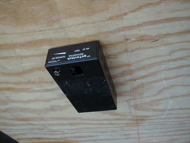
N6EACTIVATOR
Aug 12, 2001AT132-AT Activator
Equipment Class
DCD - Part 15 Low Power Transmitter Below 1705 kHz
N6E-132-RDS
Oct 25, 1999DCD - Part 15 Low Power Transmitter Below 1705 kHz
Equipment Class
DCD - Part 15 Low Power Transmitter Below 1705 kHz
N6E-132-RDF
Oct 08, 1999DCD - Part 15 Low Power Transmitter Below 1705 kHz
Equipment Class
DCD - Part 15 Low Power Transmitter Below 1705 kHz