N6EACTIVATORAT132-AT Activator
Axcess International Inc.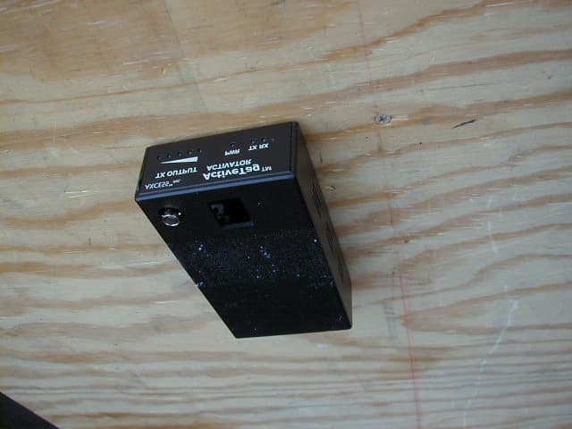
Click to zoom
Application Details
- Equipment Class
- DCD - Part 15 Low Power Transmitter Below 1705 kHz
- Date of Grant
- Aug 12, 2001
- Application Purpose
- Original Equipment
- Date of Application
- Aug 12, 2001
- Equipment Note
- AT132-AT Activator
- Frequency Range
- 0.12600000 - 0.12600000
- Company
- Axcess International Inc.
- Country
- United States
Documents & Files
Document Text
Text extracted from the exhibit documents filed with the FCC. Open a document above to read the original.
Users Manual
ActiveTag TM System Installation Manual Notices 2750.001.004 R0033© 2001 AXCESS Inc. Notices © 2001, AXCESS Inc.750.001.004 R00333 Notices Information provided in this manual is a result of the design and development of AXCESS Inc. products and is subject to change without notice. It applies only to current AXCESS Inc. RFID systems. No part of this manual may be reproduced, translated or transmitted, in any form or by any means, without the prior written consent of AXCESS Inc. FCC Rules Note: This equipment has been tested and found to comply with the limits for a Class B digital device, pursuant to Part 15 of the FCC Rules. These limits are designed to provide reasonable protection against harmful interference in a residential installation. This equipment generates, uses, and can radiate radio frequency energy and, if not installed and used in accordance with the instructions, may cause harmful interference to radio communications. However, there is no guarantee that interference will not occur in a particular installation. If this equipment does cause harmful interference to radio or television reception, which can be determined by turning the equipment off and on, the user is encouraged to try to correct the interference by one or more of the following measures: • Reorient or relocate the receiving antenna • Increase the separation between the equipment and receiver • Connect the equipment into an outlet on a circuit different from that to which the receiver is connected • Consult the dealer or an experienced radio/TV technician for help Responsibilities • AXCESS Inc. declines all liability for any damage that might result from any errors or omissions in this document or from improper installation. • AXCESS Inc. can only guarantee the correct operation of its products if they are used with the software programs, systems, and consumables supplied or authorized in writing by AXCESS Inc. • AXCESS Inc. recommends keeping the original packaging for transporting the equipment later. Registered Trademarks Product names mentioned herein may be trademarks and/or registered trademarks of their respective companies. Notices 4750.001.004 R0033© 2001 AXCESS Inc. Customer Service AXCESS Inc. toll-free support line is 1-800-577-6080. Representatives are available from 7:30 – 6:30 Central Time. U.S. Patents 4,816,9014,843,4664,847,677 4,849,8074,857,9914,857,993 4,914,5085,140,4126,034,603 Other patents pending. © 2001, AXCESS Inc.750.001.004 R00335 Table of Contents GENERAL INSTALLATION INFORMATION ........................................................................... 9 S AFETY ................................................................................................................................... 9 I NFORMATION F LAGS ................................................................................................................ 9 H AND T OOLS , E QUIPMENT AND M ATERIALS ............................................................................. 10 Required ........................................................................................................................... 10 Recommended ................................................................................................................. 11 ACTIVETAG SYSTEM OVERVIEW........................................................................................ 13 A CTIVE T AG S YSTEM C OMPONENTS ........................................................................................ 13 T AGS ..................................................................................................................................... 14 A CTIVATOR ............................................................................................................................ 14 R ECEIVER .............................................................................................................................. 15 Filters................................................................................................................................ 16 Serial Output .................................................................................................................... 16 Wiegand Output ............................................................................................................... 16 IP Output .......................................................................................................................... 16 T RANSMIT A NTENNAS ............................................................................................................. 16 Types of Transmit Antennas ............................................................................................ 16 SYSTEM CONFIGURATION BASICS.................................................................................... 19 I NTRODUCTION ....................................................................................................................... 19 A PPLICATION T YPES .............................................................................................................. 19 Vehicle.............................................................................................................................. 19 Personnel and/or Asset .................................................................................................... 20 M ULTIPLE A CTIVATOR A PPLICATIONS ...................................................................................... 21 I NSTALLATION T IPS ................................................................................................................ 21 Waterproofing...................................................................................................................21 Checking Activation Fields ............................................................................................... 22 Cable Length for Antennas..........................................................................…
Text truncated - open the document above for the full version.
Block Diagram
C:\DRAWINGS\named_dwgs\AT-132_ACT_BLK_DIAG.dwg, Acrobat PDFWriter
External Photos
External Photos N6EACTIVATOR FCC ID: N6EACTIVATOR FCC ID: N6EACTIVATOR
ID Label/Location Info
C:\DRAWINGS\named_dwgs\label\AT-132_ACT_LBLXB.dwg, 03/21/01 04:50:55 PM, Acrobat PDFWriter MANUFACTURING FRACTIONS: ± 1/64 [0.4mm] ANGLES: ± 0.5° DECIMALS: XX±0.010[0.25mm] XXX±0.005[0.13mm] ENGINEERING REPRODUCE OR DISCLOSE THE DOCUMENT, ANY PART THEREOF NOTICE-THIS DOCUMENT DISCLOSES SUBJECT MATTER IN WHICH POSSESSION THEREOF CONFERS OR TRANSFERS ANY RIGHT TO AXCESS INC. HAS PROPRIETARY RIGHTS. NEITHER RECEIPT NOR BY WRITTEN PERMISSION FROM, OR WRITTEN AGREEMENT WITH DEVICE, OR TO PRACTICE ANY METHOD OR PROCESS, EXCEPT ANY INFORMATION CONTAINED THEREIN, OR ANY ARTICLE OR AXCESS INC. MDL #: AT-132- ACTIVATOR RATED VOLTAGE: 24DC, 1A interference received, including (2) This device must accept any interference, and Operation is subject to the following This device complies with part interference that may cause FCC ID.: N6EACTIVATOR (1) This device may not cause harmful two conditions: 15 FCC Rules. undesired operations.
ID Label/Location Info
C:\DRAWINGS\numbered_dwgs\8\800077001A.dwg
Internal Photos
Internal Photos FCC ID: N6EACTIVATOR FCC ID: N6EACTIVATOR
Operational Description
3208 C OMMANDER D RIVE C ARROLLTON , TX 75006 P HONE : 972-407-6080 F AX : 972.407.9085 WWW . AXCESSINC . COM M E M O R A N D U M Date:March 29, 2001 To:Whom It May Concern From: Ken Larkin Subject: Equipment Installation AXCESS Inc. sells equipment through a group of Certified Dealers and Authorized Distributors. These qualified dealers and distributors have been fully trained to assure high quality and professional installation. The training and the documentation stress the importance of using only the approved installation techniques and materials. Ken Larkin VP Technology AXCESS Inc.
Operational Description
ACTIVATOR AT132-AT Technical Description Overview: The function of the Activator is to broadcast a signal, which contains the Activator’s ID. When a Tag passes through this field, it will wake up and broadcast that Activator’s ID and the Tag’s ID. This information is then utilized by a local or remote system to determine such things as location/tracking of the Tag and to perform operations like opening a portal. Block Diagram Description: The power supply inputs 24VDC from a wall mount unit. The Activator both utilizes and converts the 24VDC to 12VDC and 5VDC. The micro processor (up) operates from a single 5MHz crystal from which all timing is derived. On power up, the micro processor is initialized, reads the Unit Number Switches (ID) and then steps through an automatic tuning loop. The 132 kHz transmitter is then tuned by sampling the output transmitter voltage and switching in tuning capacitors, via a triac bank, to obtain the best match to the antenna. The antenna consists of a number of turns of wire, wound to achieve 100uH of inductance. A capacitance is added to resonate the antenna to the proper frequency. The transmitter can be disabled externally via an optically isolated interface. The programming connector is used to modify the micro processor’s operation and can only be changed by the manufacturer. Off board communications and some parameter changes can be accomplished via a serial (RS232) connection. The display connector is not utilized at this time but can used to perform either parallel or serial operations. Additionally this port can be used for I/O expansion.
Schematics
L:\Beber\FCC\Activator1.dwg, 03/13/01 05:36:21 PM, Acrobat PDFWriter L:\Beber\FCC\Activator3.dwg L:\Beber\FCC\Activator2.dwg, 03/13/01 05:39:07 PM, Acrobat PDFWriter
Test Report
EMC TEST REPORT COMPANY:AXCESS Inc. PRODUCT(S): AT-132, Activator FCC ID: N6EACTIVATOR REPORT No: J20033561.021 APPROVED BY:Yuriy Litvinov TEST ENGINEER:Norman Shpilsher DATE: August 8, 2001TOTAL PAGES: 23 All services undertaken are subject to the following general policy: Reports are submitted for exclusive use of the client to whom they are addressed. Their significance is subject to the adequacy and representative character of the samples and to the comprehensiveness of the tests, examinations or surveys made. This test report and certificate may only be reproduced in its entirety with the written permission of Intertek Testing Services management. The report must not be used by the client to claim product endorsement by NVLAP or any agency of the U.S. Government. The NVLAP logo is applicable for testing to I EC/CISPR 22:1993 and FCC-47 CFR part 15 only. A TABLE OF CONTENTS 1.0General Description ............................................................................................1 1.1Related Submittal(s) Grants ..........................................................................1 1.2Product Description ...................................................................................1 1.3Test Methodology .....................................................................................1 1.4Test Facility ............................................................................................1 2.0System Test Configuration ...................................................................................2 2.1Justification .............................................................................................2 2.2EUT Exercising Software ............................................................................2 2.3Special Accessories....................................................................................2 2.4Equipment Setup .......................................................................................2 2.5Equipment Modification ..............................................................................2 2.6Support Equipment List and Description ..........................................................2 2.7Test Configuration Block Diagram .................................................................2 3.0Emission Results ................................................................................................3 3.1Field Strength Calculation............................................................................3 3.2Radiated Emission Data ..............................................................................4 3.3Test Equipment ........................................................................................5 4.0Test Procedures .................................................................................................6 EXHIBIT I Test Set Up Photographs .......................................................................................7 EXHIBIT II Emissions Test Data........................................................................................... 12 EXHIBIT III FCC ID Label Location ...................................................................................... 20 EXHIBIT IV Internal Photographs .......................................................................................... 21 EXHIBIT V Electrical Schematics and Block Diagram................................................................. 22 EXHIBIT VI User Manual and Operational Description ................................................................ 23 A FCC ID: N6EACTIVATORReport No: J20033565.021 – August 2001 Page 1 of 23 1.0 GENERAL DESCRIPTION 1.1 Related Submittals Grants This is single application of the AT-132, Activator for Certification under Part 15.209 There are no other simultaneous applications . 1.2 Product Description Purpose of the AT-132, Activator The Activator is a stand-alone transmitter that connects directly to an application-specific antenna to provide a low frequency activation signal that awakens tags as they pass through antenna’s field. AT-132, Activator Transmitter The AT-132 Activator has 126kHz transmitter tuned by sampling the output transmitter voltage and switching in tuning capacitors, via a triac bank, to obtain the best match to the antenna. AT-132, Activator Antenna The AT-132 Activator external antenna consists of a number of turns of wire, wound to achieve 100 μ H of inductance. A capacitance is added to resonate the antenna to the proper frequency. The activator connects to antenna via coax cable with BNC connectors. 1.3Test Methodology Radiated emission measurements were performed according to the procedures in ANSI C63.4 (1992). All measurements were performed in 3m full size Anechoic Chamber. Preliminary scans were performed in the 3m full size Anechoic Chamber only to determine worst case modes. For each scan, the procedure for maximizing emissions in Appendices D and E were followed. All Radiated tests were performed at an antenna to EUT distance of 3 meters, unless stated otherwise in the " Justification Section " of this Application. 1.4Test Facility The test site facility used to collect the radiated and conducted measurement data is located at 7250 Hudson Blvd., Oakdale, Minnesota. This test facility has been fully described in a report dated on May 2000 A FCC ID: N6EACTIVATORReport No: J20033565.021 – August 2001 Page 2 of 23 submitted to your office. Please reference the Registration number: 90706, dated May 19,2000. 2.0SYSTEM TEST CONFIGURATION 2.1Justification N/A 2.2 EUT Exercising Software N/A 2.3Special Accessories There are no special accessories necessary for compliance of these products. 2.4Equipment Setup The EUT was setup as tabletop equipment, the EUT transmitting antenna was mounted on the plastic foam board. The EUT was powered at 120VAC/60Hz through Sceptre AC Adapter PD2410APL6A 120VAC/24VDC. The Activator was connected to the Antenna via coax cable…
Text truncated - open the document above for the full version.
Test Setup Photos
TEST SETUP PHOTOS Radiated Emissions FCC ID: N6EACTIVATOR FCC ID: N6EACTIVATOR Line Conducted Emissions FCC ID: N6EACTIVATOR FCC ID: N6EACTIVATOR
Contact Information
Applicant
Raj Bridgelall(VP Engineering & CTO)
Technical Contact
Intertek Testing Services NA Inc.Norman Shpilsher
[email protected](651) 730-1188
7250 Hudson Blvd., Suite 100 · Oakdale, Minnesota · United States
Non-Technical Contact
Intertek Testing Services NA Inc.Kristi Iwen
[email protected](651) 730-1188
Test Firm
Intertek Testing ServicesUri Spector
Technical Specifications
| # | Rule Parts | Frequency Range | Power Output |
|---|---|---|---|
| 1 | 15C | 0.126 MHz - 0.126 MHz | - |
Other Applications from Axcess International Inc.

N6E-433NUDOT09
Feb 04, 2010NUDOT ACTIVE RFID TAG
Equipment Class
DSC - Part 15 Security/Remote Control Transmitter
N6E-433DOT07
Feb 06, 2008DotTM Credential Tag
Equipment Class
DSC - Part 15 Security/Remote Control Transmitter
N6E-132-TAG
Nov 03, 1999DSC - Part 15 Security/Remote Control Transmitter
Equipment Class
DSC - Part 15 Security/Remote Control Transmitter
N6E-132-RDS
Oct 25, 1999DCD - Part 15 Low Power Transmitter Below 1705 kHz
Equipment Class
DCD - Part 15 Low Power Transmitter Below 1705 kHz
N6E-132-RDF
Oct 08, 1999DCD - Part 15 Low Power Transmitter Below 1705 kHz
Equipment Class
DCD - Part 15 Low Power Transmitter Below 1705 kHz