N6K-DB202Dual Channel Deactivator
HANGZHOU CENTURY CO., LTD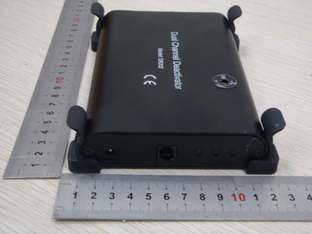
Click to zoom
Application Details
- Equipment Class
- DXT - Part 15 Low Power Transceiver, Rx Verified
- Date of Grant
- Nov 07, 2012
- Application Purpose
- Original Equipment
- Date of Application
- Nov 07, 2012
- Equipment Note
- Dual Channel Deactivator
- Frequency Range
- 8.20000000 - 8.20000000
- Company
- HANGZHOU CENTURY CO., LTD
- Country
- China
Documents & Files
Document Text
Text extracted from the exhibit documents filed with the FCC. Open a document above to read the original.
Users Manual
DUAL CHANNEL DEACTIVATOR DB202 SYSTEM DESCRIPTION COMPONENTS INSTRUCTION DB202 is a RF deactivator with 2 channels, can be deactivate 8.2MHz RF label. If none deactivate RF label or RF hard tag close to, it will beep to remind you. Deactivate range:7.6-8.8MHz. No need to synchronize with other EAS system. Can be match with speaker socket outside device to adjust the beep volume. Detecting 30cm, deactivation 25cm. DSP technology. Control Box Deactivate Pad Port P2 of Deactivate pad Port P1 of Deactivate pad Power port Speaker socket outside port Deactivate LED Detect LED Power LED Volume adjustment device Plug 1 2 Insert the control box into the bracket. Fix the bracket of control box under the counter. COUNTER Control box HOW TO INSTALL THE BRACKET Screw holes HOW TO ADJUST THE VOLUME Use the screwdriver to clockwise or anticlockwise the volume adjustment device, which locates on the control box, to change the volume. Bracket of control box USE GUIDE BEFORE OPERATION 1. Connect the deactivate Pad to the port P1 or P2 of control box. 2. Plug the power on, LED of control box flashes Red and beeps one to remind you the DB202 can be work now. OPERATION NOTICE If Deactivable RF label is above the deactivate pad about 30cm and keeps down to the pad, the deactivate control box beeps one time and detect LED flashes green, it's means RF label is nearby. If deactivate control box beeps 2 times and deactivate LED flashes yellow, detect LED flashes green, it's means the RF label is deactivated. When the deactivable RF label close to the pad, detect LED will flash green, please keep the label closer to the pad, until control box beeps 2 times of deactivate indicator to prevent false indicator. NOTICE 1. Keep the deactivate pad away from POS machine, computer of 0.5M, to prevent false alarming. 3. When use with 1 channel, please plug the port of the other, in order to avoid the interfere of the other channel. 2. Keep the pad to mental parts 4cm side distance and 30cm above of mental parts to prevent reduce the deactivation. SPECIFICATION Deactivate Pad Size: 306X256X11.5mm N.W.: 0 64kg. Control Box Size: N.W.: <200mA 156X108X26mm 0 64kg Input: 12~15VDC Idle current: <120mA Beep current: . Power Adaptor Input: 100~240VAC, 50Hz/60Hz, 0.30A Out12VDC, 1.25Aput: 3.According to customer's actual reuirementthe pad may be positioned transversely or vertically FCC STATEMENT 1. This device complies with Part 15 of the FCC Rules. Operation is subject to the following two conditions: (1) This device may not cau se harmful interference. (2) This device must accept any interference received, including interference that may cause undesired operation. 2. Changes or modifications not expressly approved by the party responsible for compliance could void the user's authority to operate the equipment. NOTE: This equipment has been tested and found to comply with the limits for a Class B digital device, pursuant to Part 15 of the FCC Rules. These limits are designed to provide reasonable protection against harmful interference in a residential installation. This equipment generates uses and can radiate radio frequency energy and, if not installed and used in accordance with the instructions, may cause harmful interference to radio communications. However, there is no guarantee that interference will not occur in a particular installation. If this equipment does cause harmful interference to radio or television reception, which can be determined by turning the equipment off and on, the user is encouraged to try to correct the interference by one or more of the following measures: ǂ Reorient or relocate the receiving antenna. ǂ Increase the separation between the equipment and receiver. ǂ Connect the equipment into an outlet on a circuit different from that to which the receiver is connected. ǂ Consult the dealer or an experienced radio/TV technician for help.
Cover Letter(s)
SCS-F18: Project and Product Certification Representative Authorization Letter Page 1 of 2 Rev 3.0 775 Montague Expressway Milpitas, CA 95035 Tel: 408-526-1188 Fax: 408-526-1088 Email: [email protected] Project and Product Certification Representative Authorization Letter Revision History Reason for Amendment (current / obsolete) From To Approved Date Initial Release (obsolete) 1.0 1.0 Nov-14-2006 Revised wording (obsolete) 1.0 2.0 Sept–25-2007 Updated company template (current) 2.0 3.0 Jan-31-2012 SCS-F18: Project and Product Certification Representative Authorization Letter Page 2 of 2 Rev 3.0 HANGZHOU CENTURY CO., LTD October 24, 2012 To: SIEMIC, INC. 775 Montague Expressway, Milpitas, CA 95035 USA Dear Sir/Madam, Re: Project and Product Certification Representative Authorization Letter We, HANGZHOU CENTURY CO., LTD hereby authorize SIEMIC, INC. to act as a Certification Body for certifying for the following project(s): FCC ID: N6K-DB202 Dual Channel Deactivator Model name: DB202 We affirm that between SIEMIC and HANGZHOU CENTURY CO., LTD, any difference in understanding, including test plan, measurement methods, applicable standards and relevant procedures and processes have been resolved prior to commencement of testing activities. Sincerely, Haibo Zhang Title: Test Leader HANGZHOU CENTURY CO., LTD Address: 1418-48# Moganshan Road, Hangzhou, Zhejiang, P.R.China Telephone: 0086-571-28818606 Fax : 0086-571-28818660 E-mail: [email protected]
Cover Letter(s)
SCS-F19: Confidentiality Request Letter Page 1 of 2 Rev 3.0 775 Montague Expressway Milpitas, CA 95035 Tel: 408-526-1188 Fax: 408-526-1088 Email: [email protected] Confidentiality Request Letter Revision History Reason for Amendment (current / obsolete) From To Approved Date Initial Release (obsolete) 1.0 1.0 Nov-14-2006 Adding CFR 2.459 (obsolete) 1.0 2.0 August – 11 - 2008 Updated company template & Added text box (current) 2.0 3.0 Jan-31-2012 SCS-F19: Confidentiality Request Letter Page 2 of 2 Rev 3.0 HANGZHOU CENTURYCO., LTD October 24, 2012 To: Federal Communications Commission Authorization and Evaluation Division 7435 Oakland Mills Road Columbia, MD Subject: Permanent Confidentiality Request for FCC ID: N6K-DB202 We hereby request confidential treatment of information accompanying this application as outlined below: - Block Diagram - Schematics - Operational Description The above materials contain trade secrets and proprietary information not customarily released to the public. The public disclosure of these materials may be harmful to the applicant and provide unjustified benefits to its competitors. The applicant understands that pursuant to Section 0.457 & 0.459 of the Rules, disclosure of this application and all accompanying documentation will not be made before the date of the Grant for this application. Sincerely, Haibo Zhang Title: Test Leader HANGZHOU CENTURY CO., LTD Address: 1418-48# Moganshan Road, Hangzhou, Zhejiang, P.R.China Telephone: 0086-571-28818606 Fax : 0086-571-28818660 E-mail: [email protected]
External Photos
External photos
ID Label/Location Info
HANGZHOU CENTURY CO.,LTD FCC ID:N6K-DB202 This device complies with part 15 of the FCC Rules. Operation is subject to the following two conditions:(1)this device may cause harmful interference, and (2)this device must accept any interference received, including interference that may cause undesired operation.
ID Label/Location Info
Label Location
Internal Photos
Internal photos Antenna
Test Report
NINGBO EMTEK CO., LTD. REPORT NO: KAN120830051E FCC ID: N6K-DB202 DATE: 10/24/2012 Page 1 of 27 ELECTROMAGNETIC EMISSIONS COMPLIANCE REPORT INTENTIONAL RADIATOR CERTIFICATION TO FCC PART 15 SUBPART B &C REQUIREMENT OF Dual Channel Deactivator MODEL No.: DB202 FCC ID: N6K-DB202 REPORT NO: KAN120830051E ISSUE DATE: October 24, 2012 Prepared for HANGZHOU CENTURY CO., LTD 1418-48# Moganshan Road Hangzhou, Zhejiang, P.R.China Prepared by NINGBO EMTEK CO., LTD 1F Building 4, 1177#, Lingyun Road, National Hi-Tech Zone, Ningbo, Zhejiang, China TEL: 0086-574-27907998 FAX: 0086-574-27721538 NINGBO EMTEK CO., LTD. REPORT NO: KAN120830051E FCC ID: N6K-DB202 DATE: 10/24/2012 Page 2 of 27 VERIFICATION OF COMPLIANCE Applicant: HANGZHOU CENTURY CO., LTD 1418-48# Moganshan Road Hangzhou, Zhejiang, P.R.China Product Description: Dual Channel Deactivator Model Number: DB202 File Number: KAN120830051E Date of Test: October 8, 2012 to October 23, 2012 We hereby certify that: The above equipment was tested by NINGBO EMTEK CO., LTD. The test data, data evaluation, test procedures, and equipment configurations shown in this report were made in accordance with the procedures given in ANSI C63.4 (2009) and the energy emitted by the sample EUT tested as described in this report is in compliance with conducted and radiated emission limits of FCC Rules Part 15.223. The test results of this report relate only to the tested sample identified in this report. Approved By Andy.wang/Manager NINGBO EMTEK CO., LTD. NINGBO EMTEK CO., LTD. REPORT NO: KAN120830051E FCC ID: N6K-DB202 DATE: 10/24/2012 Page 3 of 27 Table of Contents 1. GENERAL INFORMATION........................................................................................................... 4 1.1. Product Description...................................................................................................................... 4 1.2. Related Submittal(s) / Grant (s) ................................................................................................... 4 1.3. Test Methodology ........................................................................................................................ 4 1.4. Special Accessories ...................................................................................................................... 4 1.5. Equipment Modifications............................................................................................................. 4 1.6. Test Facility.................................................................................................................................. 5 1.7. Measurement Uncertainty ............................................................................................................ 5 2. SYSTEM TEST CONFIGURATION ............................................................................................. 6 2.1. EUT Configuration ...................................................................................................................... 6 2.2. EUT Exercise ............................................................................................................................... 6 2.3. Requirement for Compliance ....................................................................................................... 6 2.4. Configuration of Tested System................................................................................................... 7 2.5. Description of support units ......................................................................................................... 8 3. SUMMARY OF TEST RESULTS ................................................................................................... 8 4. DESCRIPTION OF TEST MODES................................................................................................ 8 5. CONDUCTED EMISSIONS TEST ................................................................................................ 9 5.1. Measurement Procedure:.............................................................................................................. 9 5.2. Test SET-UP................................................................................................................................. 9 5.3. Measurement Equipment Used: ................................................................................................... 9 5.4. Measurement Result:.................................................................................................................. 10 5.5. Conducted Measurement Photos:............................................................................................... 11 6. RADIATED EMISSION TEST ..................................................................................................... 12 6.1. Measurement Procedure............................................................................................................. 12 6.2. Measurement Equipment Used: ................................................................................................. 12 6.3. Test SET-UP............................................................................................................................... 13 6.4. Radiated Measurement Result ................................................................................................... 14 6.5. Radiated Measurement Photos:.................................................................................................. 17 7. EMISSION BANDWIDTH ............................................................................................................ 21 7.1. Measurement Procedure............................................................................................................. 21 7.2. Measurement Equipment ...........................................................................................................21 7.3. Test Setup ................................................................................…
Text truncated - open the document above for the full version.
Test Setup Photos
Setup photos 1. Conducted: 2. Radiated: 30M~1000MHz: 9K~30MHz:
Contact Information
Applicant
Deyun Cong(Test Leader)
Test Firm
EMTEK (NINGBO) CO.,LTD.Andy Wang
Technical Specifications
| # | Rule Parts | Frequency Range | Power Output |
|---|---|---|---|
| 1 | 15C | 8.2 MHz - 8.2 MHz | - |
Other Applications from HANGZHOU CENTURY CO., LTD
N6K-CER320
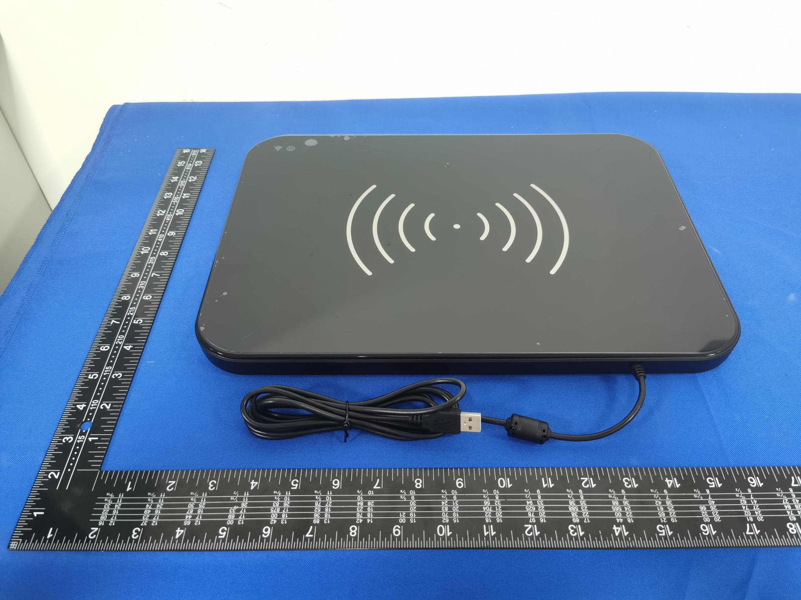
Nov 30, 2023RFID Desk Reader
Equipment Class
DSS - Part 15 Spread Spectrum Transmitter
N6K-CE39034
Nov 29, 2020Smart Shelf Counter
Equipment Class
DXX - Part 15 Low Power Communication Device Transmitter
N6KCA3000L
Nov 08, 2020FCC Quarzo Classic
Equipment Class
DXT - Part 15 Low Power Transceiver, Rx Verified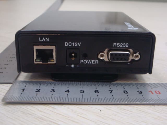
N6K-WB-DB308
Aug 29, 2012ESL Wirless Basestation
Equipment Class
DXT - Part 15 Low Power Transceiver, Rx Verified
N6K-ESL-T817
Jun 04, 2012Electronic Shelf Label
Equipment Class
DXX - Part 15 Low Power Communication Device Transmitter