N6KCA3000LFCC Quarzo Classic
HANGZHOU CENTURY CO., LTD
Click to zoom
Application Details
- Equipment Class
- DXT - Part 15 Low Power Transceiver, Rx Verified
- Date of Grant
- Nov 08, 2020
- Application Purpose
- Original Equipment
- Date of Application
- Nov 08, 2020
- Equipment Note
- FCC Quarzo Classic
- Frequency Range
- 8.20000000 - 8.20000000
- Company
- HANGZHOU CENTURY CO., LTD
- Country
- China
Documents & Files
Document Text
Text extracted from the exhibit documents filed with the FCC. Open a document above to read the original.
Users Manual
User Manual of Century RF System Standard Series (CA3000L Mainboard) Firmware: V2.08, Software: V1.16, Manual version: V1.01 Copyright © 2019 Hangzhou Century Co., Ltd. All rights reserved. 1 2 R evision History Date Revision Description 12/15/2016 1.00 First Release 04/22/2017 1.01 Installation scheme added 3 Content 1.GENERAL INFORMATION ...................................................................... 3 2. OVERVIEW OF SYSTEMS ....................................................................... 4 2.1.Appearance & Structure of Antenna .......................................................................... 4 2.2. Power Supply Unit ........................................................................................................ 4 2.3.Synchronization .......................................................................................................... 5 2.4.Alarm .......................................................................................................................... 5 2.4.1.Alarm and Background Light ................................................................................... 5 2.4.2.Relay Output ............................................................................................................ 5 2.4.3.PCB Layout and Wire Connection ........................................................................... 6 3.HARDWARE ADJUSTMENTS AND TSETS ................................................ 7 3.1.LED Indicators ............................................................................................................. 7 3.2.Oscilloscope Observation and Test Points .................................................................. 7 4.SOFTWARE CONFIGURATION .................................................................................. 8 5.INSTALLATION GUIDE .............................................................................. 8 5.1 Recommended Arrangement of Antenna Frame and Door Frame ............................... 8 5.2 Preparation before Installation .................................................................... 9 6. SERVICE SUPPORT ..................................................................................... 9 4 1. GENERAL INFORMATION WARNING The electronics inside antennas are extremely sensitive to electrostatic discharges. Always discharge yourself by touching a ground point before touching any of the electronics to avoid damaging the circuits. PRECAUTION The electricity supplied to the systems shall not be shared with other electronic or electric loads, e.g. electronic transformers, neon/spot lights, electrical engines, computers, LCD screens and cash registers, etc. PRECAUTION “Dead” (not working) antenna(s) close to working antenna(s) will cause serious interference to the working antenna(s). To avoid the interference, RX- and RX+ of the “dead” antenna(s) must be short circuited. The use of the prepared short-circuit connector is shown as below. 5 2.O VERVIEW OF SYSTEMS 2.1.Appearance & Structure of Antenna 2.2. Power Supply Unit WARNING: One power adapter is preferred to work with one CA3000L mainboard only. If the quality of power source is not good enough, the external filter shall be used (as shown below). WARNING: Do not tie 24V and 220V cables together, as AC may generate interference to the system. Antenna frame CA3000L 6 2.3.S ynchronization Century Mono RF systems are compatible with other Mono systems. But Dual systems can interfere with all Mono systems (not only Century’s). So, Century Mono systems must be kept at least ten (10) meters away from any Dual system. Otherwise, the performance of the Mono systems will be affected. 2.4.Alarm When a tag is detected, both audible (buzzer) and visual (LED light) alarms will be triggered. Different alarm-related parameters can be set by Century RFC software (see chapter “Software Configuration”). The buzzer is connected to the BEEP terminal (SOUND+ and SOUND-). Pay attention to the polarity of the buzzer. 2.4.1.Alarm and Background Light The alarm light is connected to LED connector (V+ R G B). The working voltage and current of lamp are 24VDC and 50mA. There are 7 optional alarm colors available, which can be selected by Century RFC software (see chapter “Software Configuration”). The Background light is connected to LED connector (V+ R G B). The working voltage and current of lamp are 24VDC and maximum 600mA. There are 7 optional colors available, which can be selected by Century RFC software (see chapter “Software Configuration”). 2.4.2.Relay Output Mode of control is Normal Open (NC). When an alarm is triggered, the relay will switch to CCTV on. Please be aware that the relay can be used to control many kinds of external device, such as access control systems, although it is marked for CCTV application. 7 2.4.3.PCB La yout and Wire Connection (1&4—O) (2&5—8) (3&6—88) Noise Indicator WIFI CCTV Power Indicator Light Buzzer RS 232 Fuse DC Out DC In TX Loop RX2 Loop RX1 Loop 0V 24V Status Indicator Alarm LED DSP In RX Gain Power Level Volume 8 3. HARDWARE ADJUSTMENTS AND TSETS 3.1.LED Indicators LED colour Name Description RED LED1 The power is normal RED LED02 Noise Level 7 Noise High Noise Low The higher noise level, the worse performance. RED LED03 Noise Level 6 RED LED04 Noise Level 5 RED LED05 Noise Level 4 YELLOW LED09 Noise Level 3 YELLOW LED08 Noise Level 2 GREEN LED07 Noise Level 1 GREEN LED06 Noise Level 0 RED LED4 It is ON when the alarm is triggered. RED LED3 It is blinking when the system is running normally. 3.2.Oscilloscope Observation and Test Points After connecting antenna TX test point (TX--Trigger Source) and DSP-IN (P2) on oscilloscope, we can observe the transmit and receive signals (Yellow-TX and Blue-RX windows). Test Point Description GND Test reference point P2 DSP-IN TX Antenna TX test point(Trigger Source) 9 4. SO FTWARE CONFIGURATION For the software configuration, RFC software is required. And a T-cable is needed fo…
Text truncated - open the document above for the full version.
Cover Letter(s)
Company: HANGZHOU CENTURY CO., LTD Add: 1418-48# Moganshan Road, Hangzhou Zhejiang, P.R.China Tel: 0086-571-28818606 Fax: 0086-571-28818660 E-mail: [email protected] FCC Authorization Date: 2020-09-03 FEDERAL COMMUNICATIONS COMMISSION Authorization and Evaluation Division 7435 Oakland Mills Road Columbia, MD 21046 Subject: Agent Authorization To whom it may concern: We, HANGZHOU CENTURY CO., LTD, the undersigned, Hereby authorizes Bay Area Compliance Laboratories Corporation to act on its b ehalf in all ma tters relating to application for Equipment authorization, including the signing of all documents relating to these matters. All acts carried out by Bay Area Compliance Laboratories Corp. o n our behalf shall have the same effect as our own action. We, the undersigned, hereby certify that we are not subject to a denial of federal benefits, that includes FCC benefits, pursuant to Section 5301 of the Anti-Drug Abuse Act of 1988, 21 U.S.C. 862. This authorization is valid until further written notice from the applicant. Sincerely Yours, Signature: Printed Name: Deyun Cong Title: Test Leader QA-FR-170-B
Cover Letter(s)
Company: HANGZHOU CENTURY CO., LTD Add: 1418-48# Moganshan Road, Hangzhou Zhejiang, P.R.China Tel: 0086-571-28818606 Fax: 0086-571-28818660 E-mail: [email protected] FCC Confidential Authorization Date: 2020-09-03 FEDERAL COMMUNICATIONS COMMISSIONS Authorization and Evaluation Division 7435 Oakland Mills Road Columbia, MD 21046 Subject: Confidentiality Request regarding application for certification of FCC ID: N6KCA3000L To: whom it may concern, In accordance with Sections 0.457 and 0.459 of the Commission’s Rules, HANGZHOU CENTURY CO., LTD hereby requests long-term confidential treatment of informati on accompanying this application as outlined below: Block Diagram Schematics Operation Description The above materials contain proprietary and confidential information not customarily released to the public. The public disclosure of these materials provides unjustified benefits to its competitors in the market. Sincerely Yours, Signature: Printed Name: Deyun Cong Title: Test Leader
External Photos
EXHIBIT A - EUT EXTERNAL PHOTOGRAPHS
ID Label/Location Info
Model:CA3000L FCC Quarzo Classic FCC ID:N6KCA3000L
Internal Photos
EXHIBIT B - EUT INTERNAL PHOTOGRAPHS Antenna
Test Report
FCC PART 15.223 TEST REPORT For HANGZHOU CENTURY CO., LTD 1418-48# Moganshan Road, Hangzhou Zhejiang, P.R.China FCC ID: N6KCA3000L Report Type: Original Report Product Type: FCC Quarzo Classic Test Engineer: CK Huang Re port Number: RSHF200903002-00A Re port Date: 2020-10-22 Reviewed B y: Oscar Ye EMC Manager Prepared By: Bay Area Compliance Laboratories Corp. (Kunshan) No.248 Chenghu Road,Kunshan,Jiangsu province,China Tel: +86-0512-86175000 Fax: +86-0512-88934268 www.baclcorp.com.cn Bay Area Compliance Laboratories Corp. (Kunshan) Report No.: RSHF200903002-00A FCC Part 15.223 Page 2 of 22 TABLE OF CONTENTS GENERAL INFORMATION ....................................................................................................................................... 3 PRODUCT DESCRIPTION FOR EQUIPMENT UNDER TEST (EUT) ..................................................................................... 3 OBJECTIVE ................................................................................................................................................................... 3 RELATED SUBMITTAL(S)/GRANT(S) ............................................................................................................................. 3 TEST METHODOLOGY .................................................................................................................................................. 3 MEASUREMENT UNCERTAINTY .................................................................................................................................... 4 TEST FACILITY ............................................................................................................................................................. 4 SYSTEM TEST CONFIGURATION .......................................................................................................................... 5 JUSTIFICATION ............................................................................................................................................................. 5 EUT EXERCISE SOFTWARE .......................................................................................................................................... 5 EQUIPMENT MODIFICATIONS ....................................................................................................................................... 5 SUPPORT EQUIPMENT LIST AND DETAILS .................................................................................................................... 5 EXTERNAL I/O CABLE .................................................................................................................................................. 5 BLOCK DIAGRAM OF TEST SETUP ................................................................................................................................ 6 SUMMARY OF TEST RESULTS ............................................................................................................................... 8 TEST EQUIPMENT LIST ........................................................................................................................................... 9 FCC§15.203 - ANTENNA REQUIREMENT ............................................................................................................ 10 APPLICABLE STANDARD ............................................................................................................................................ 10 ANTENNA CONNECTED CONSTRUCTION .................................................................................................................... 10 FCC §15.207 (A) – AC LINE CONDUCTED EMISSIONS .................................................................................... 11 APPLICABLE STANDARD ............................................................................................................................................ 11 EUT SETUP ................................................................................................................................................................ 11 EMI TEST RECEIVER SETUP ....................................................................................................................................... 11 TEST PROCEDURE ...................................................................................................................................................... 11 FACTOR & OVER LIMIT CALCULATION ...................................................................................................................... 12 TEST RESULTS SUMMARY .......................................................................................................................................... 12 TEST DATA ................................................................................................................................................................ 12 FCC§15.223, §15.205 & §15.209 - RADIATED EMISSIONS TEST ...................................................................... 15 APPLICABLE STANDARD ............................................................................................................................................ 15 EUT SETUP ................................................................................................................................................................ 15 EMI TEST RECEIVER SETUP ....................................................................................................................................... 16 CORRECTED AMPLITUDE & MARGIN CALCULATION ................................................................................................. 16 TEST RESULTS SUMMARY .......................................................................................................................................... 16 TEST DATA ..........................................................................................................…
Text truncated - open the document above for the full version.
Test Setup Photos
EXHIBIT C - TEST SETUP PHOTOGRAPHS Conducted Emissions (Front View) Conducted Emissions (Side View) Radiated Emissions (9kHz-30MHz) Radiated Emissions (30MHz-1GHz)
Contact Information
Applicant
Deyun Cong(Test Leader)
Test Firm
Bay Area Compliance Laboratories Corp. (Kunshan)Mr. John Chan
[email protected]+86 0512 86175000
Technical Specifications
| # | Rule Parts | Frequency Range | Power Output |
|---|---|---|---|
| 1 | 15C | 8.2 MHz - 8.2 MHz | - |
Other Applications from HANGZHOU CENTURY CO., LTD
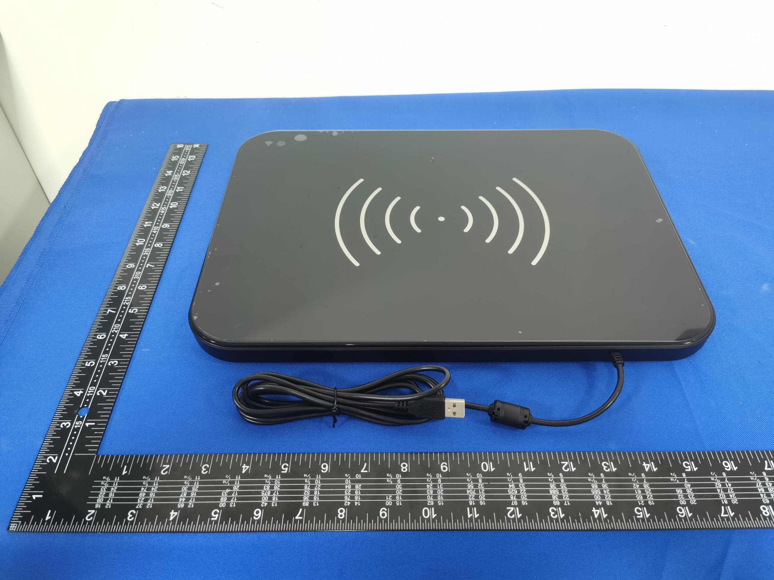
N6K-CER320
Nov 30, 2023RFID Desk Reader
Equipment Class
DSS - Part 15 Spread Spectrum Transmitter
N6K-CE39034
Nov 29, 2020Smart Shelf Counter
Equipment Class
DXX - Part 15 Low Power Communication Device Transmitter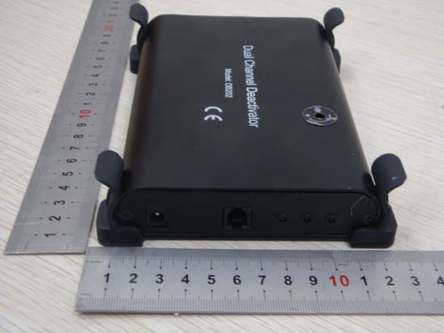
N6K-DB202
Nov 07, 2012Dual Channel Deactivator
Equipment Class
DXT - Part 15 Low Power Transceiver, Rx Verified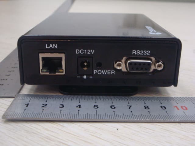
N6K-WB-DB308
Aug 29, 2012ESL Wirless Basestation
Equipment Class
DXT - Part 15 Low Power Transceiver, Rx Verified
N6K-ESL-T817
Jun 04, 2012Electronic Shelf Label
Equipment Class
DXX - Part 15 Low Power Communication Device Transmitter