N8NLSD4BT-S95S95 module
Lierda Science & Technology Group Co.,Ltd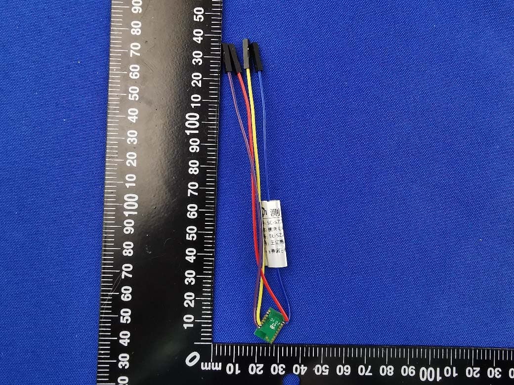
Click to zoom
Application Details
- Equipment Class
- DTS - Digital Transmission System
- Date of Grant
- Jul 02, 2020
- Application Purpose
- Original Equipment
- Date of Application
- Jul 02, 2020
- Equipment Note
- S95 module
- Frequency Range
- 2402.00000000 - 2480.00000000
- Country
- China
Documents & Files
Document Text
Text extracted from the exhibit documents filed with the FCC. Open a document above to read the original.
Users Manual
Page 1 of 21 S95 Series products Product Specification Product name: S95 BLE StandardModule Model:LSD4BT-S95ALSP001 File Version:Rev01 Page 2 of 21 File Rivision History Serial number Modify log ModifierReviewer File version Modified date 01 Initial version 杨彬 孙香涛 Rev01 2020-5-28 Page 3 of 21 Catalog CHAPTER 1 OVERVIEW ....................................................................................................................... 4 1.1 E91A MODULE FEATURES ........................................................................................................................ 4 1.2 APPLICATION ........................................................................................................................................ 5 CHAPTER 2 SPECIFICATIONS .............................................................................................................. 6 CHAPTER 3 HARDWARE LAYOUT AND INTERFACE DESCRIPTION ......................................................... 8 3.1 DIMENSIONAL DRAWING ......................................................................................................................... 8 3.2 DIMENSIONAL DRAWING ......................................................................................................................... 9 CHAPTER 4 APPLICATION NOTE ....................................................................................................... 11 4.1 ANTENNA DESIGN GUIDE ....................................................................................................................... 11 4.2 BACKPLANE LAYOUT CONSIDERATIONS ...................................................................................................... 12 4.3 DISTANCE TEST INSTRUCTIONS ................................................................................................................ 13 4.4 BROADCAST AND CONNECTION POWER TEST .............................................................................................. 14 4.5 PRECAUTIONS ..................................................................................................................................... 15 CHAPTER 5 PRODUCTION GUIDANCE ............................................................................................... 16 5.1 PRODUCTION GUIDE ............................................................................................................................. 16 5.2 MODULE REQUIREMENTS FOR FLOOR POSITION .......................................................................................... 16 5.3 STEEL STENCIL DESIGN ........................................................................................................................... 17 5.4 REFLOW SOLDERING INSTRUCTIONS ......................................................................................................... 18 CHAPTER 6 PRODUCT PACKAGING ................................................................................................... 19 6.1 PACKAGING METHOD ............................................................................................................................ 19 6.2 STRIP SIZE .......................................................................................................................................... 19 6.3 PRODUCT DIRECTION ............................................................................................................................ 19 CHAPTER 7 RF EXPOSURE INFORMATION AND STATEMENT .............................................................. 20 ADVISE THE USER ............................................................................................................................ 21 Page 4 of 21 Chapter 1 Overview The S95 standard hardware module is a high-performance IoT Bluetooth transceiver based on the NORDIC Bluetooth SOC nRF52 series (supporting Bluetooth 5.0). The module uses a stamp-type interface; the package is compatible with the E66 module (Pin-to-Pin) and supports both external antennas and on-board antennas. The product has the characteristics of low power consumption, small size and strong anti-interference ability. Based on the optimized Bluetooth SDK provided by Lierda, users can easily develop Bluetooth applications, shorten the development cycle, and help you seize market opportunities. Table 1-1 Model Description Model Description LSD4BT-S95 nRF52805, external antenna and on-board antenna, this model does not include software. For software product, please confirm the model and MPQ information with the sales. 1.1 E91A module features ● Bluetooth 5 ● ARM® Cortex®-M4 32-bit processor, 64 MHz ● 192 KB Flash + 24 KB RAM ● LEmode:1 Mbps ● Link Budget:98dB ● Receive sensitivity:-94dB ● Output power:MAX 4dBm ● RSSI accuracy:1dB ● Working voltage:1.7-3.6V ● Number of configurable GPIO :10 ● ADC accuracy:12bit / 200 ksps ● 50ΩRF port1 ● Programmable peripheral interface-PPI ● DC-DC work mode Page 5 of 21 1.2 Application ● 2.4GHz low power Bluetooth system; ● Low-power peripherals such as PC, tablet, mobile phone, and handset(HID, remote controler, etc.); ● Comsumer eletronics such as sport and health care; ● Wireless sensor networks such as smart metes and data acquisition; ● Intelligent cloud platform and ecologic access(WeChat, QQ IOT, Jingdong, Ali, Xiaomi, etc. ); ● Smart home, LAN, interactive devices, beacon lights. Page 6 of 21 Chapter 2 Specifications Table 2-1 Product limit parameters The main parameters Performance Remarks Minim um Maximu m Power supply voltage(V) -0.3 3.9 IO voltage(V) -0.3 VDD+0.3 Not more than 3.9 Maximum RF input power(dBm) / 10 Storage voltage(°C) -40 +125 Working temperature(°C) -40 +85 VESD Electrostatic discharge(ESD) performance Human Body Model(HBM),CLASS 2 / 2000V Charged Device Model(CDM) / 1000V Table 2-2 Module working temperature@25°C The main parameters Performance Remarks Minimu m Typical Maximu m Working voltage(V) 1.7 3.3 3.6 Ripple requirements:peak to peak voltage < 30mV …
Text truncated - open the document above for the full version.
Users Manual
ORIGINAL EQUIPMENT MANUFACTURER (OEM) NOTES The OEM must certify the final end product to comply with unintentional radiators (FCC Sections 15.107 and 15.109) before declaring compliance of the final product to Part 15 of the FCC rules and regulations. Integration into devices that are directly or indirectly connected to AC lines must add with Class II Permissive Change. The OEM must comply with the FCC labeling requirements. If the module’s label is not visible when installed, then an additional permanent label must be applied on the outside of the finished product which states: “Contains transmitter module FCC ID: N8NLSD4BT‐S95. Additionally, the following statement should be included on the label and in the final product’s user manual: “This device complies with Part 15 of the FCC Rules. Operation is subject to the following two conditions: (1) This device may not cause harmful interferences, and (2) this device must accept any interference received, including interference that may cause undesired operation.” The module is allowed to be installed in mobile and portable applications A module or modules can only be used without additional authorizations if they have been tested and granted under the same intended end‐use operational conditions, including simultaneous transmission operations. When they have not been tested and granted in this manner, additional te sting and/or FCC application filing may be required. The most straightforward approach to address additional testing conditions is to have the grantee responsible for the certification of at least one of the modules submit a permissive change application. When having a module grantee file a permissive change is not practical or feasible, the following guidance provides some additional options for host manufacturers. Integrations using modules where additional testing and/or FCC application filing(s) may be required are: (A) a module used in devices requiring additional RF exposure compliance information (e.g., MPE evaluation or SAR testing); (B) limited and/or split modules not meeting all of the module requirements; and (C) simultaneous transmissions for independent collocated transmitters not previously granted together. This Module is full modular approval, it is limited to OEM installation ONLY. Integration into devices that are directly or indirectly connected to AC lines must add with Class II Permissive Change. (OEM) Integrator has to assure compliance of the entire end product include the integrated Module. Additional measurements (15B) and/or equipment authorizations (e.g. Verification) may need to be addressed depending on co-location or simultaneous transmission issues if applicable. (OEM) Integrator is reminded to assure that these installation instructions will not be made available to the end user
Cover Letter(s)
Lierda Science & Technology Group Co.,Ltd, Date: 01 June, 2020 To: Federal Communications Commission, Authorization & Evaluation Division, 7435 Oakland Mills Road, Columbia, MD 21046 RE: Lierda Science & Technology Group Co.,Ltd, FCC ID: N8NLSD4BT‐S95 FCC Certification Confidentiality Request Gentlemen: This letter is to comply with 47 CFR 0.457 and 0.459 pertaining to confidentiality material. Lierda Science & Technology Group Co.,Ltd, requests that the following documents regarding this submission for FCC ID : N8NLSD4BT‐S95 be kept Long‐Term confidential: Exhibit Type File Name Block Diagram Block Diagram.pdf Schematics Schematics.pdf Operational Description Operational Description.pdf And below exhibit kept short‐term confidential (180 days): Exhibit Type File Name External Photos External Photo.pdf Internal Photos Internal Photo.pdf Test Setup Photos Test Setup Photos.pdf Users Manuals Users Manual.pdf Those documents contain detailed system and equipment description and related information about the product which Lierda Science & Technology Group Co.,Ltd, considers to be confidential proprietary, a custom design and, otherwise, not releasable to the general public. Since this design is a basis form which future technological products will evolve, Lierda Science & Technology Group Co.,Ltd, considers this information would be of benefit to its competitors, and that the disclosure of the information in these documents would give competitors an unfair advantage in the market. Thank you for your attention to this matter. Yours Sincerely, (signature) Print name: Henry Kim Title: Test Mangaer Lierda Science & Technology Group Co.,Ltd,
Cover Letter(s)
Lierda Science & Technology Group Co.,Ltd, Date: 01 June, 2020 To: Federal Communications Commission, Authorization & Evaluation Division, 7435 Oakland Mills Road, Columbia, MD 21046 To Whom It May Concern: The Lierda Science & Technology Group Co.,Ltd, the undersigned, hereby authorizes Mr. Wu Xuewen from Shenzhen BALUN Technology Co., Ltd., to act on the behalf of the Lierda Science & Technology Group Co.,Ltd, solely in matters relating to the application for an FCC equipment authorization for FCC ID: N8NLSD4BT‐S95 including the signing of documents in connection with this Application. Necessary acts carried out by Shenzhen BALUN Technology Co., Ltd. in connection with the Application shall have the same effect as acts of the Lierda Science & Technology Group Co.,Ltd,. The Lierda Science & Technology Group Co.,Ltd, also hereby certify that no party to this application is subject to a denial of benefits, including FCC benefits, pursuant to Section 5301 of the Anti‐Drug Abuse Act of 1988, 21 U.S.C. Section 862. Yours Sincerely, (signature) Print name: Henry Kim Title: Test Mangaer Lierda Science & Technology Group Co.,Ltd,
Cover Letter(s)
Modular Approval Request FCC (KDB 996369 D01 & Part 15.212) FCC ID: _ N8NLSD4BT-S95 _ Items to be covered by Single modular transmitters. Answer from applicant 1. The modular transmitter must have its own RF shielding. Yes 2. The modular transmitter must have buffered modulation/data inputs (if such inputs are provided) to ensure that the module will comply with Part 15 requirements under conditions of excessive data rates or over-modulation. Yes 3. The modular transmitter must have its own power supply regulation. Yes 4. The modular transmitter must comply with the antenna requirements of Section 15.203 and 15.204(b)(c). The antenna must either be permanently attached or employ a “unique” antenna coupler (at all connections between the module and the antenna, including the cable). Yes 5. The modular transmitter must be tested in a stand-alone configuration, i.e., the module must not be inside another device during testing. This is intended to demonstrate that the module is capable of complying with Part 15 emission limits regardless of the device into which it is eventually installed. Yes 6. The modular transmitter must be equipped with either a permanently affixed label or must be capable of electronically displaying its FCC identification number in accordance with 15.212 (a)(1)(vi)(A) / (B). Yes 7. The modular transmitter must comply with any specific rule or operating requirements applicable to the transmitter and the manufacturer must provide adequate instructions along with the module to explain any such requirements. A copy of these instructions must be included in the application for equipment authorization. For example, there are very strict operational and timing requirements that must be met before a transmitter is authorized for operation under Section 15.231. For instance, data transmission is prohibited, except for operation under Section 15.231(e), in which case there are separate field strength level and timing requirements. Compliance with these requirements must be assured. Yes 8. The modular transmitter must comply with any applicable RF exposure requirements. For example, FCC Rules in Sections 1.1310, 2.1091, 2.1093, and specific Sections of Part 15, including 15.319(i), 15.407(f), 15.253(f) and 15.255(g), require that Unlicensed PCS, UNII and millimeter wave devices perform routine environmental evaluation for RF Exposure to demonstrate compliance. In addition, spread spectrum transmitters operating under Section 15.247 are required to address RF Exposure compliance. Modular transmitters approved under other Sections of Part 15, when necessary, may also need to address certain RF Exposure concerns, typically by providing specific installation and operating instructions for users, installers and other interested parties to ensure compliance. Yes Items to be covered by Split modular transmitters. Answer from applicant 1. The modular transmitter must comply with all requirements of a single modular transmitter except for items (1) & (5) of the above single modular approval requirements. 2. Only the radio front end must be shielded. The physical crystal and tuning capacitors may be located external to the shielded radio elements. The interface between the split sections of the modular system must be digital with a minimum signalling amplitude of 150 mV peak-to-peak. 3. Control information and other data may be exchanged between the transmitter control elements and radio front end. 4. The sections of a split modular transmitter must be tested installed in a host device(s) similar to that which is representative of the platform(s) intended for use. 5. Manufacturers must ensure that only transmitter control elements and radio front end components that have been approved together are capable of operating together. The transmitter module must not operate unless it has verified that the installed transmitter control elements and radio front end have been authorized together. Manufacturers may use means including, but not limited to, coding in hardware and electronic signatures in software to meet these requirements, and must describe the methods in their application for equipment authorization. Note: A limited modular approval (LMA) may be granted for single or split modular transmitters that comply partially with the requirements above. Name and surname of applicant (or authorized representative): ___Henry Kim_____ Date: _2020-06-01___ Signature: ___________________________
Cover Letter(s)
Lierda Science & Technology Group Co.,Ltd Request for Superceeding Federal Communication Commission Equipment Authorization Division, Application Processing Branch 7435 Oakland Mills Road Columbia, MD 21048 Date: Jul. 06, 2020 TO WHOM IT MAY CONCERN Hereby we requests to supersede follow data from application FCC ID: N8NLSD4BT‐S95 Exhibit Type: Description: EUT internal photo EUT internal photo.pdf EUT external photo EUT external photo.pdf RF test setup photo RF test setup photo.pdf Reason: Due to our mistake, the following documents are incomplete and need to be updated The files have been uploaded again by using correct Exhibit Type. Thanks for your attention. Yours Sincerely, Contact: Henry Kim Title: Test Mangaer Lierda Science & Technology Group Co.,Ltd
External Photos
Annex No.: BL-SZ2040 839-AW 1 / 7 EUT EXTERNAL PHOTOS FRONT VIEW OF EUT REAR VIEW OF EUT Annex No.: BL-SZ2040 839-AW 2 / 7 LEFT SIDE VIEW OF EUT RIGHT SIDE OF EUT Annex No.: BL-SZ2040 839-AW 3 / 7 TOP VIEW OF EUT BOTTOM VIEW OF EUT Annex No.: BL-SZ2040 839-AW 4/ 7 EUT EXTERNAL PHOTOS FRONT VIEW OF EUT REAR VIEW OF EUT Annex No.: BL-SZ2040 839-AW 5 / 7 LEFT SIDE VIEW OF EUT RIGHT SIDE OF EUT Annex No.: BL-SZ2040 839-AW 6 / 7 TOP VIEW OF EUT BOTTOM VIEW OF EUT Annex No.: BL-SZ2040 839-AW 7 / 7 Accessory-Antenna
ID Label/Location Info
LSD4BT-S95ALSP001_Label 1、Label Content 2、Label Size 10.26mm(L)X 7.8mm(W) 3、Label Location Note: The label is attached to the shield of the module as shown above.
Internal Photos
Annex No.: BL-SZ2040 839-AI 1 / 4 EUT INTERNAL PHOTOS EUT UNCOVER VIEW MAIN BOARD TOP VIEW RF Chip Ceramic Antenna Annex No.: BL-SZ2040 839-AI 2 / 4 MAIN BOARD REAR VIE Annex No.: BL-SZ2040 839-AI 3 / 4 EUT INTERNAL PHOTOS EUT UNCOVER VIEW MAIN BOARD TOP VIEW RF Chip Annex No.: BL-SZ2040 839-AI 4 / 4 MAIN BOARD REAR VIE 9
RF Exposure Info
RF Exposure Evaluation for FCC ID: N8NLSD4BT-S95 Refer user manual this device is a S95 module, and this device was designed used in portable devices that the minimum distance between human’s body is 5mm. Based on the 47CFR 2.1093, this device belongs to portable device. The definition of the category as following: Portable Derives: CFR Title 47 §2.1093(b) (b) For purposes of this section, a portable device is defined as a transmitting device designed to be used so that the radiating structure(s) of the device is/are within 20 centimeters of the body of the user. FCC KDB 447498 D01 General RF Exposure Guidance v06 Limit Unless specifically required by the published RF exposure KDB procedures, standalone 1-g head or body and 10-g extremity SAR evaluation for general population exposure conditions, by measurement or numerical simulation, is not required when the corresponding SAR Test Exclusion Threshold condition, listed below, is satisfied. These test exclusion conditions are based on source- based time-averaged maximum conducted output power of the RF channel requiring evaluation, adjusted for tune-up tolerance, and the minimum test separation distance required for the exposure conditions. The minimum test separation distance is determined by the smallest distance from the antenna and radiating structures or outer surface of the device, according to the host form factor, exposure conditions and platform requirements, to any part of the body or extremity of a user or bystander. The 1-g and 10-g SAR test exclusion thresholds for 100 MHz to 6 GHz at test separation distances ≤ 50 mm are determined by: [(max. power of channel, including tune-up tolerance, mW) / (min. test separation distance, mm)] · [√f(GHz) ] ≤ 3.0 for 1-g SAR and ≤ 7.5 for 10-g extremity SAR Where • f (GHz) is the RF channel transmit frequency in GHz • Power and distance are rounded to the nearest mW and mm before calculation • The result is rounded to one decimal place for comparison The test exclusions are applicable only when the minimum test separation distance is ≤ 50 mm and for transmission frequencies between 100 MHz and 6 GHz. When the minimum test separation distance is < 5 mm, a distance of 5 mm is applied to determine SAR test exclusion. Test data Bluetooth Mode GFSK (BLE) Low Channel Middle Channel High Channel Peak Power (dBm) 4.36 4.18 3.99 Note: This report listed the worst case peak power value, please refer to RF test report for more details. Turn-up power Mode Range (dBm) Bluetooth 3.50-4.50 FCC exclusion condition= [2.82 mW/5 mm] · [√2.48 GHz] = 0.9 < 3.0 RF Exposure Evaluation Result: Pass Note: More power data, Please refer to the RF report.
Test Report
Report No.: BL-SZ2040839-601 2 / 62 Revision History Version Issue Date Revisions Content Rev. 01 Jun. 30, 2020 Initial Issue TABLE OF CONTENTS 1 ADMINISTRATIVE DATA (GENERAL INFORMATION) .......................................................................... 5 1.1 Identification of the Testing Laboratory ....................................................................................... 5 1.2 Identification of the Responsible Testing Location ...................................................................... 5 1.3 Laboratory Condition ................................................................................................................... 5 1.4 Announce .................................................................................................................................... 5 2 PRODUCT INFORMATION ...................................................................................................................... 6 2.1 Applicant Information ................................................................................................................... 6 2.2 Manufacturer Information ............................................................................................................ 6 2.3 Factory Information ..................................................................................................................... 6 2.4 General Description for Equipment under Test (EUT) ................................................................ 6 2.5 Technical Information .................................................................................................................. 7 2.6 Additional Instructions ................................................................................................................. 8 3 SUMMARY OF TEST RESULTS .............................................................................................................. 9 3.1 Test Standards ............................................................................................................................ 9 3.2 Verdict ......................................................................................................................................... 9 4 GENERAL TEST CONFIGURATIONS ................................................................................................... 10 4.1 Test Environments .................................................................................................................... 10 4.2 Test Equipment List ................................................................................................................... 10 4.3 Measurement Uncertainty ......................................................................................................... 11 4.4 Description of Test Setup .......................................................................................................... 12 4.4.1 For Antenna Port Test ............................................................................................................... 12 4.4.2 For AC Power Supply Port Test ................................................................................................ 12 4.4.3 For Radiated Test (Below 30 MHz) ........................................................................................... 13 4.4.4 For Radiated Test (30 MHz-1 GHz) .......................................................................................... 13 4.4.5 For Radiated Test (Above 1 GHz) ............................................................................................. 14 4.5 Measurement Results Explanation Example ............................................................................. 15 4.5.1 For conducted test items: .......................................................................................................... 15 Report No.: BL-SZ2040839-601 3 / 62 4.5.2 For radiated band edges and spurious emission test: ............................................................... 15 5 TEST ITEMS ........................................................................................................................................... 16 5.1 Antenna Requirements .............................................................................................................. 16 5.1.1 Relevant Standards ................................................................................................................... 16 5.1.2 Antenna Anti-Replacement Construction .................................................................................. 16 5.1.3 Antenna Gain ............................................................................................................................ 16 5.2 Output Power ............................................................................................................................ 17 5.2.1 Test Limit ................................................................................................................................... 17 5.2.2 Test Setup ................................................................................................................................. 17 5.2.3 Test Procedure .......................................................................................................................... 17 5.2.4 Test Result ................................................................................................................................ 18 5.3 Occupied Bandwidth ................................................................................................................. 19 5.3.1 Limit ........................................................................................................................................... 19 5.3.2 Test Setup ................................................................................................................................. 19 5.3.3 Test Procedure ..................................…
Text truncated - open the document above for the full version.
Test Setup Photos
Annex No.: BL-SZ2040 839-AR 1 / 10 TEST SETUP PHOTOS 1 Radiated Test Photo Below 30MHz Close-up Annex No.: BL-SZ2040 839-AR 2 / 10 30MHz-1 GHz Close-up Annex No.: BL-SZ2040 839-AR 3 / 10 Above 1GHz Close-up Annex No.: BL-SZ2040 839-AR 4 / 10 2 Conducted Test Photo Conducted Test-BLE 3 Conducted Emissions Test Photo 1 Annex No.: BL-SZ2040 839-AR 5 / 10 Test Photo 2 Annex No.: BL-SZ2040 839-AR 6 / 10 TEST SETUP PHOTOS 1 Radiated Test Photo Below 30MHz Close-up Annex No.: BL-SZ2040 839-AR 7 / 10 30MHz-1 GHz Close-up Annex No.: BL-SZ2040 839-AR 8/ 10 Above 1GHz Close-up Annex No.: BL-SZ2040 839-AR 9 / 10 2 Conducted Test Photo Conducted Test-BLE 3 Conducted Emissions Test Photo 1 Annex No.: BL-SZ2040 839-AR 10 / 10 Test Photo 2
Contact Information
Applicant
Qingqing Sun(Certified Engineer)
Test Firm
Shenzhen BALUN Technology Co., Ltd.Hanson Lin
[email protected]86-755-66833830
Technical Specifications
| # | Rule Parts | Frequency Range | Power Output |
|---|---|---|---|
| 1 | 15C | 2.40 GHz - 2.48 GHz | 2.73 mW |
Other Applications from Lierda Science & Technology Group Co.,Ltd
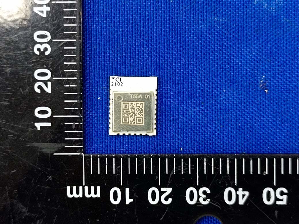
N8NLSD4BT-T55
Aug 24, 2021Bluetooth Module
Equipment Class
DTS - Digital Transmission System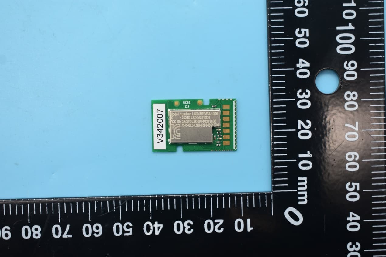
N8NLSD4RF043610D0
Mar 03, 20212.4GHz Wireless Module
Equipment Class
DXX - Part 15 Low Power Communication Device Transmitter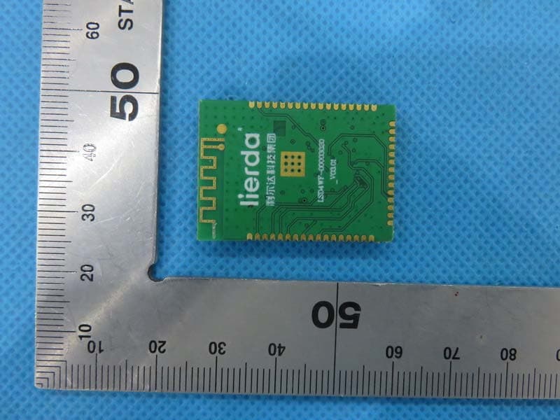
N8NLSD4WF
Jul 09, 2015WiFi Module
Equipment Class
DTS - Digital Transmission System
N8NLSD4BTP74MSTD1
Feb 15, 2015P-series BLE Module
Equipment Class
DTS - Digital Transmission System
N8NLSD4BT212-06D0
Jun 08, 2014Bluetooth Module
Equipment Class
DTS - Digital Transmission System