N99J447RModel 2WFMR - hand-held transceiver
Firstech, Inc.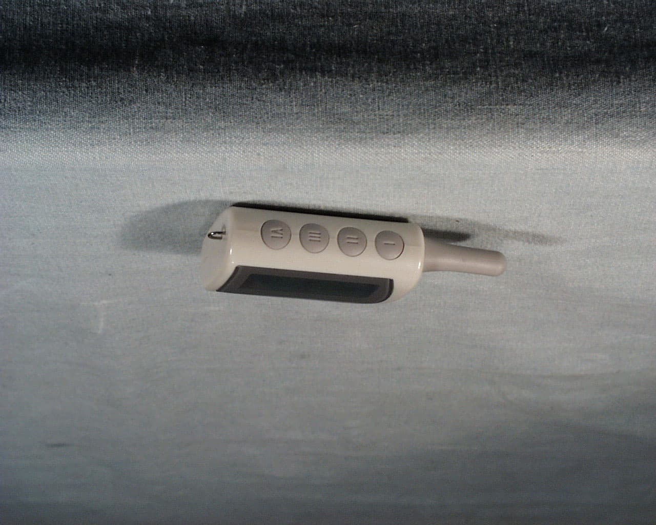
Click to zoom
Application Details
- Equipment Class
- DSC - Part 15 Security/Remote Control Transmitter
- Date of Grant
- Feb 12, 2002
- Application Purpose
- Original Equipment
- Date of Application
- Feb 12, 2002
- Equipment Note
- Model 2WFMR - hand-held transceiver
- Frequency Range
- 447.70000000 - 447.70000000
- Company
- Firstech, Inc.
- Country
- United States
Documents & Files
Document Text
Text extracted from the exhibit documents filed with the FCC. Open a document above to read the original.
Users Manual
© 2001 Firstech, Inc. Page 1 Two-Way FM Remote USER’S GUIDEUSER’S GUIDE By Firstech, Inc. Website: www.compustar.org © 2001 Firstech, Inc. Page 2 TABLE OF CONTENTSTABLE OF CONTENTS Safety Information...............................................................Page 3 Remote-Pager: 2WFMR w/LCD......................................................3 CompuGLO color LCD (Liquid Crystal Display)..................................4 Remote-Pager Button Functions................................................... 5 Remote-Pager Learn Routine...................................................... 6 Alarm Mode...............................................................................6 Dual Stage Shock Sensor............................................................ 7 Auto-start Function..................................................................... 7 Reservation Mode......................................................................8 Trunk Release .....................................................................10 Query Function ..........................................................................10 Panic Mode..............................................................................10 Valet Mode ...............................................................11 Timer Start Mode...........................................................................11 Safety Shutdown Features.............................................................12 RPS (Remote Paging System).........................................................12 Optional Programmable Features ...................................................12 Ignition Lock ...........................................................................12 Auto Arming ...........................................................................12 Passive Arming.........................................................................13 Turbo Mode...........................................................................13 Optional Installation Features.........................................................14 Cold Start Mode .....................................................................14 Optional Auxiliary 1 & Auxiliary 2................................................14 Warranty.....................................................................14 Important Information: This Device complies with Part 15 of the FCC Rules. Operation is subject to the following two conditions: (1) This Device may not cause harmful interference,, and (2) This Device must accept any interference received, Including interference that may cause undesired operation Caution: Changes or modifications could void the authority of the user to operate this device. © 2001 Firstech, Inc. Page 3 Safety Information Safety Information Please take these safety precautions under the following conditions: 1. Servicing the vehicle When servicing (i.e. changing the oil, washing your car) your automobile, the CompuStar system should be in Valet Mode. There is a safety shutdown switch under the hood that deactivates the remote starter function if the hood is open. However, if the switch has been damaged or the switch has been installed improperly, the vehicle may start when Button II is pressed for 2 seconds even if the hood is open. 2. Loaning your vehicle to others Whenever you loan your vehicle to an individual who is not familiar with Compustar, please put the vehicle in Valet mode. This will prevent the vehicle loaner from accidentally activating the CompuStar auto-security system. 3. For manual transmission vehicles If the Compustar 2WSSR is installed in a manual transmission vehicle, extra precautions are required because the Compustar does not monitor the gear shift: Important! Under normal circumstances, Reservation Mode is cancelled when a door or hatchback opens. Please verify if the opening of any door or hatchback cancels Reservation Mode. If any of the doors or hatchback is not monitored by CompuStar because of improper installation or a faulty dome light switch, do not use the CompuStar and take your vehicle to the dealer immediately for repair. Do not set Reservation Mode when the window(s) are open or if there is anyone inside of the vehicle including animals. RemoteRemote--Pager: 2WFMR w/LCDPager: 2WFMR w/LCD The model name, 2WFMR, stands for Two Way Frequency Modulation Remote with Liquid Crystal Display. This transmitter that allows you to activate multiple © 2001 Firstech, Inc. Page 4 functions by pressing a combination of 4 buttons on the unit in order to transmit signals. CompuGLO color LCDCompuGLO color LCD The remote-pager comes with CompuGLO which is a unique color LCD display that visually tells the vehicle owner the security status of your car at all times. There are differing icons that will appear on your CompuGLO LCD indicating what your vehicle is currently doing. Icon Explanation Auto N/A Turbo IndicateS if Turbo Mode is on or off. Timer Indicates if Timer Start Mode is on or off. Passive Indicates if Passive Arming Mode is on or off. Hammer Indicates that the first or second stage shock sensor has been triggered. Remote Vibration Indicates that Shock sensor is by-passed or not. Zzzz Indicates if you are in Valet Mode. Parking Lights Indicates if your car parking lights are flashing. Car Siren Indicates that your car siren is turned on or off when you lock or unlock the vehicle. Phone Indicates that someone is paging you from your vehicle. Lock/Unlock Displays if your car is armed or disarmed. Transmitting Indicates if your remote-pager is transmitting signals to the controller unit. Battery Displays remaining battery life. Blinking Battery while engine running Displays running time left – each bar represents 25% of the running time. Door Displays if your door is open. Exhaust Fumes Displays if your vehicle has auto-started properly or ignition on. Trunk Displays if your trunk is open. Hood Displays if your hood is open. © 2001 First…
Text truncated - open the document above for the full version.
Block Diagram
N99J447R Block Diagram (B1<Block1> ~ B12<Block12>) Antenna ReceiverTrans mitter B2. +DC 1.5V Battery B1. Buttons B3. Micro-Controller (KS57C21208) B4. Real Time Clock (4 M Hz) B5. RF –Output Power Enable/Disable B6. Modulation B7. Output Oscillator B8. First Filter B9. First Amplify B10. Second Filter B11. Second Amplify B12. Third Filter 447.70MHz/9 447.70MHz/3 447.70MHz B13. Low Noise A mplify B19. RF –Input Power Enable/Disable B18. Discriminator B14. First Local Oscillator (469.10 M Hz) B15. First Mixer(21.4M Hz) B16. Second Local Oscillator (20.945MHz) B17. Second Mixer(455KHz) Receiver I.c.
Cover Letter(s)
801 E. 82nd St., Unit 1, Anchorage, Alaska 99518 USA Phone (907) 563-8648 ~ Fax (907) 563-8642 [email protected] www.compustar.org CONFIDENTIALITY REQUEST LETTER FEDERAL COMMUNICATIONS COMMISSION 7435 Oakland Mills Road Columbia, MD 21046 Subject: Request for Confidentiality FCC ID: N99J447R To Whom it May Concern: In accordance with §0.459 of CFR 47, Firstech, Inc. requests confidentiality for the following items: 1. Block Diagram 2. Schematic Diagrams 3. Theory of Operation These items contain detailed system and equipment description and related information about the product which Firstech, Inc. considers to be proprietary, confidential and a custom design which otherwise would not be released to the general public. Since this design is a basis from which future technological products will evolve, Firstech, Inc. also feels that this information would be of benefit to its competitors, and that the disclosure of the information in these exhibits would give our competitors an unfair advantage in the market. Best regards, Ken H. Lee Design Engineer
External Photos
COMMUNICATION CERTIFICATION LABORATORY TEST REPORT: 73-7694 FCC ID: N99J447R Page 23 of 29 Front View Of The EUT COMMUNICATION CERTIFICATION LABORATORY TEST REPORT: 73-7694 FCC ID: N99J447R Page 24 of 29 Back View Of The EUT COMMUNICATION CERTIFICATION LABORATORY TEST REPORT: 73-7694 FCC ID: N99J447R Page 25 of 29 Side View Of The EUT Showing The Buttons
ID Label/Location Info
FC C I D : N 9 9 J44 7 R Re m o t e B o t t o m V i e w FC C I D : N9 9 J 4 4 7 R P r o p o s ed L a be l Lo c a t io n F C C L abe l Loc a t io n
Internal Photos
COMMUNICATION CERTIFICATION LABORATORY TEST REPORT: 73-7694 FCC ID: N99J447R Page 26 of 29 Front View Of the LCD PCB COMMUNICATION CERTIFICATION LABORATORY TEST REPORT: 73-7694 FCC ID: N99J447R Page 27 of 29 Back View Of The LCD PCB COMMUNICATION CERTIFICATION LABORATORY TEST REPORT: 73-7694 FCC ID: N99J447R Page 28 of 29 Front View Of The Antenna Daughter Board COMMUNICATION CERTIFICATION LABORATORY TEST REPORT: 73-7694 FCC ID: N99J447R Page 29 of 29 Back View Of The Antenna Daughter Board
Operational Description
Description of the Electrical Circuitry Hand Held Transceiver N99J447R A) When one or more of the buttons of the Transceiver is pressed: 1) When one or more of I, II, III or IV buttons is/are pressed, the button instruction is transferred to U2 (CPU). 2) U2 (CPU) transfers the ID code and button instruction to Q7. 3) Q7 generates the radio frequency carrier of 447.7 MHz that was modulated by the data from U2. 4) The signal from Q7 is amplified by the Transistor Q5, Q6, then sent to Antenna T1. B) When a signal enters from the antenna: 1) U2 (CPU) monitors the 447.7 MHz through Antenna T1. 2) When U2 receives 447.7 MHz signal, the signal is amplified by Transistor Q1, Q2, then sent to the Mixer Transistor Q3. 3) Q8 sends self-generated frequency 455 MHz to Mixer Transistor Q3. 4) Transistor Q3 heterodynes the signals from Q1,2 to generate 21.4Mhz that is sent to Intermediate Frequency IC, U1. 5) Intermediate Frequency IC demodulate the signal to digital code and then send it to U2 (CPU). 6) The CPU recognizes the ID and instruction, then activates the Beeper Buz1 and indicates the information on the LCD1.
Schematics
1 1 2 2 3 3 4 4 5 5 6 6 7 7 8 8 AA BB CC DD R7000-O1A0 R7000 REMOTE RF FCC ID : N99J447R B 22Monday, November 26, 2001 Title SizeDocument NumberRev Date:Sheetof VDD DT1 C28 X2 469.10MHz X3 20.945MHz X1 447.70MHz TC1 10uF + Q4 KTA1504GR L3 18NH L4 18NH L13 1uH L14 1uH L5 2.7uH L6 15NH L8 15NH L9 100nH L10 100nH L11 820nH L12 820nH R1 390K R3 18K R6 33 R26 18K R27 22K R7 330 R8 22K R9 1.5K R30 22K R10 3.3K R11 68K R12 68K R13 68K R21 33K R23 47K C4 15P C6 220P C7 0.01u C12 18P C11 0.01u C14 1000P C15 33P C16 39P C18 0.1u C21 0.01u C20 560P C19 3300P C23 220P C29 220P C31 NU C32 3P C34 1P C37 220P C41 10P TC3 10uF + C17 0.1u Q5 2SC4226(R25) Q6 2SC4226(R25) Q7 2SC4226(R25) Q8 2SC4226(R25) Q2 2SC4226(R25) Q1 2SC4226(R25) Q3 2SC4226(R25) VC2 6PT C38 18P C39 39P R20 NU C35 2P C33 5P R17 22K C30 5P R31 18K C24 4P C22 6P C47 0.5P R29 1K C46 2P R28 560 C44 33P C43 33P C63 22P L2 22NH C3 220P ANT1 ANRENNA R18 560 C1 12P L1 18NH C2 5P C9 NU C10 22P VC3 10PT C42 6P C45 220P L15 18NH CF1 455E R14 470 R15 270 C28 1P L7 15NH C27 2P C26 2P C25 NU R2 100K L16 18NH C48 3P R16 NU R5 NU R4 100 C13 1000P MCF1 21N15A C49 1P D3 KDV154 R22 4.7K C36 0.01u L60 22nH C8 5P C61 NU C62 1P C60 1P CON2 6PIN + 1 + 3 + 5 + 2 + 4 + 6 CON1 4PIN + 1 + 3 + 2 + 4 U1 TA31145FN XIN 1 XOU 2 MXO 3 VCC 4 IFI 5 DEC 6 REF 7 QUAD 8 AFO 9 RSSI 10 LFI 11 LPO 12 BS 13 CHA 14 FOUT 15 ALM 16 RGO 18 RGC 17 GND 19 MXI 20 TC2 22uF + C50 0.01u R19 2K D1 MMBV3401 D2 MMBV3401 TC4 22uF + C100 0.01u L100 0ohm L101 0ohm C101 NU C102 NU C103 NU 1 1 2 2 3 3 4 4 11 22 33 44 POWER SECTION1 R7000-01A01 R7000 REMOTE LOGIC FCC ID : N99J447R A3 00Monday, November 26, 2001 Title SizeDocument NumberRev Date:Sheet of 1.5V 1.5V 3V 3V 1.5V 1.5V 3V CON1 4PIN 1 3 2 4 SW4 SKQD L1 100uH BATT 1.5V C1 100P TC2 22u + C3 4700P D1 MA721 C2 68P U2 KS57C21208 P6.0 23 P6.1 24 P6.2 25 P6.3 26 P7.0 27 P7.1 28 P7.2 29 P7.3 30 C7 31 C6 32 C5 33 P2.0 1 P2.1 2 P2.2 3 P2.3 4 VDD 5 VSS 6 MXOUT 7 MXIN 8 TE ST 9 SXIN 10 SXOUT 11 RESET 12 P0.3 13 P0.2 14 P0.1 15 P0.0 16 P3.1 17 P3.0 18 P5.0 19 P5.1 20 P5.2 21 P5.3 22 C4 34 C3 35 C2 36 C1 37 C0 38 P1.0 39 P1.1 40 P1.2 41 P1.3 42 P4.1 43 P4.0 44 X1 4MHz X2 32.768KHz C7 22P C6 22P C5 0.1u R3 NU R2 47K C4 0.1u U1 XC6383A VOUT 3 VSS 1 VDD 2 Q1 KTA1504 SW3 SKQD SW2 SKQD SW1 SKQD U4 ELM9718BA VOUT 1 VSS 2 VDD 3 R7 NU C10 0.1u U3 D355A GND 1 L- 2 VOUT 3 L+ 4 V+ 5 CLF1 6 CLF2 7 E' 8 Q2 KRC109S C8 0.01u R4 1M L2 2.2mH EL LAMP C048-BG86-CL GND 2 V+ 1 C9 0.1u Q6 KRC109S BZ BUZZER R1 100 D2 KDS193A TC1 22u + LCD BT-M400MN-82DP COM3 COM2 COM1SPK KEY-U TURBO VIB LIGHT 24H SYSTEM CAR AUTO CHOKE1 CHOKE0 CHOKE1 CALL0 CALL2 CALL1 OTHER TRUNK0 TRUNK1 LSMOKE SSMOKE MSMOKE BAT2 BAT4 BAT3 BAT1 UNLOCK DOOR0 BAT0 LOCK DOOR1 ANT KEY2 KEY COM3 1 COM2 2 COM1 3 SEG1 4 SEG2 5 SEG3 6 SEG4 7 SEG5 8 SEG6 9 SEG7 10 SEG8 11 SEG9 12 SEG10 13 SEG11 14 Q4 KRA110S R5 68K R6 68K R8 0ohm CON2 6PIN 1 3 5 2 4 6 TC3 22u + R9 100K C14 0.01u C13 0.01u C12 0.01u C11 0.01u BS RX DATA RX DATA BS 1.5V TX DATA 3V TX DATA TX POWER TX POWER
Test Report
TEST REPORT FROM: COMMUNICATION CERTIFICATION LABORATORY 1940 W. Alexander Street Salt Lake City, Utah 84119-2039 Type of Report: Certification TEST OF: 2WFMR FCC ID: N99J447R To FCC PART 15, Subpart C Section 15.231 Test Report Serial No: 73-7694 Applicant: Firstech Inc. 801 E. 82 nd Ave. Unit #1 Anchorage, AK 99518 Date of Test: January 21 st & 22 nd , 2002 Issue Date: January 31, 2002 COMMUNICATION CERTIFICATION LABORATORY TEST REPORT: 73-7694 FCC ID: N99J447R Page 2 of 29 CERTIFICATION OF ENGINEERING REPORT This report has been prepared by Communication Certification Laboratory to determine compliance of the device described below with the certification requirements of FCC Part 15, Subpart C Section 15.231. This report may be reproduced in full, partial reproduction may only be made with the written consent of the laboratory. The results in this report apply only to the sample tested. - Applicant: Firstech, Inc. - Manufacturer: Youngshin Electronics Co., LTD - Trade Name: CompuStar - Model Number: 2WFMR - FCC ID: N99J447R On this 31 st day of January 2002, I, individually, and for Communication Certification Laboratory, certify that the statements made in this engineering report are true, complete, and correct to the best of my knowledge, and are made in good faith. Although NVLAP has recognized that the Communication Certification Laboratory EMC testing facilities are in good standing, NVLAP does not endorse the product described in this report. COMMUNICATION CERTIFICATION LABORATORY Tested by: Kirk P. Thomas Project Engineer COMMUNICATION CERTIFICATION LABORATORY TEST REPORT: 73-7694 FCC ID: N99J447R Page 3 of 29 TABLE OF CONTENTS SECTION 1.0 CLIENT INFORMATION..................................4 SECTION 2.0 EQUIPMENT UNDER TEST (EUT)..........................5 SECTION 3.0 TEST SPECIFICATION, METHODS & PROCEDURES............6 SECTION 5.0 SUMMARY OF TEST RESULTS............................11 SECTION 6.0 MEASUREMENTS, EXAMINATIONS AND DERIVED RESUTLS.....12 APPENDIX 2 Photographs:........................................21 COMMUNICATION CERTIFICATION LABORATORY TEST REPORT: 73-7694 FCC ID: N99J447R Page 4 of 29 SECTION 1.0 CLIENT INFORMATION 1.1 Client Information: Company Name: Firstech Inc. 801 East 82 nd Avenue Unit #1 Anchorage, AK 99518 Contact Name: Jason Lee Title: President 1.2 Manufacturer: Company Name: YOUNGSHIN ELECTRONICS CO., LTD. 4FL Hirun Town Bldg 536-3. Unhaeng-Dong. Sihung, Kyungki-Do, KOREA 429-060 Contact Name: Young T1 Change Title: President COMMUNICATION CERTIFICATION LABORATORY TEST REPORT: 73-7694 FCC ID: N99J447R Page 5 of 29 SECTION 2.0 EQUIPMENT UNDER TEST (EUT) 2.1 Identification of EUT: Trade Name: CompuStar Model Name or Number: 2WFMR Serial Number: N/A Options Fitted: N/A Country of Manufacture: Korea 2.2 Description of EUT: The 2WFMR is a hand-held transceiver for an automobile alarm or an auto start system. The 2WFMR has 4 buttons and a LCD monitor. By pressing a button or a combination of buttons, the 2WFMR will transmit an RF signal to a transceiver installed in a vehicle. Also, upon receipt of a signal from the transceiver installed in a vehicle, the 2WFMR will demodulate and display the signal as data on the LCD with sounds. The 2WFMR described in this test report is identical to the 2WFMR certified under FCC ID# N99J2WFMR, except that this unit transmits at 447 MHz instead of 434 MHz. COMMUNICATION CERTIFICATION LABORATORY TEST REPORT: 73-7694 FCC ID: N99J447R Page 6 of 29 SECTION 3.0 TEST SPECIFICATION, METHODS & PROCEDURES 3.1 Test Specification: Title: FCC PART 15, Subpart C (47 CFR 15). Section 15.231 Periodic operation in the band 40.66-40.70 MHz and above 70 MHz. Purpose of Test: The tests were performed to demonstrate Initial compliance. 3.2 Methods & Procedures: 3.2.1 15.231 (a) The provision of this section are restricted to periodic operation within the band 40.66-40.70 MHz and above 70 MHz. Except as Shown in paragraph (e) of this section, the intentional radiator is restricted to the transmission of a control signal such as those used with alarm systems, door openers, remote switches, etc. Radio control of toys in not permitted. Continuous transmissions, such as voice or video, and data transmissions are not permitted. The prohibition against data transmissions does not preclude the use of recognition codes. Those codes are used to identify the sensor that is activated or to identify the particular component as being part of the system. The following conditions shall be met to comply with the provisions for this periodic operation: (1) A manually operated transmitter shall employ a switch that will automatically deactivate the transmitter within not more than 5 seconds of being released. (2) A transmitter activated automatically shall cease transmission within 5 seconds after activation. (3) Periodic transmissions at regular predetermined intervals are not permitted. However, polling or supervision transmission to determine system integrity of transmitters used in security or safety applications are allowed if the periodic rate of transmission does not exceed one transmission of not more than one second duration per hour for each transmitter. (4) Intentional radiators which are employed for radio control COMMUNICATION CERTIFICATION LABORATORY TEST REPORT: 73-7694 FCC ID: N99J447R Page 7 of 29 purposes during emergencies involving fire, security, and safety of life, when activated to signal an alarm, may operated during the pendency of the alarm condition. (b) In addition to the provisions of 15.205, the field strength of emission from intentional radiators operated under this section shall not exceed the following: Fundamental frequency (MHz) Field strength of fundamental (microvolts/meter) Field strength of spurious emissions (microvolts/meter) 40.66 - 40.70 2,250 225 70 –130 1,250 125 130 – 174 1,250 to 3,750 ** 125 to 375 ** 174 – 260 3,750 375 260 – 470 3,750 to 12,500 ** 375 to 1,250 ** Above 470 12,500 1,250 ** Linear interp…
Text truncated - open the document above for the full version.
Test Setup Photos
COMMUNICATION CERTIFICATION LABORATORY TEST REPORT: 73-7694 FCC ID: N99J447R Page 21 of 29 PPENDIX 2 Photographs: A Front View Of The Radiated Test Setup COMMUNICATION CERTIFICATION LABORATORY TEST REPORT: 73-7694 FCC ID: N99J447R Page 22 of 29 Back View Of The Radiated Test Setup
Contact Information
Applicant
Jason Lee(President)
Technical Contact
Firstech, Inc.Jason Lee
[email protected]907 222 3804
801 E. 82nd. Street, Unit 1 · Anchorage, Alaska · United States
Non-Technical Contact
Firstech, Inc.Jason Lee
[email protected]907 222 3804
Test Firm
Communication Certification Lab.Scott Earl
Technical Specifications
| # | Rule Parts | Frequency Range | Power Output |
|---|---|---|---|
| 1 | 15.231 | 447.7 MHz - 447.7 MHz | - |
Other Applications from Firstech, Inc.
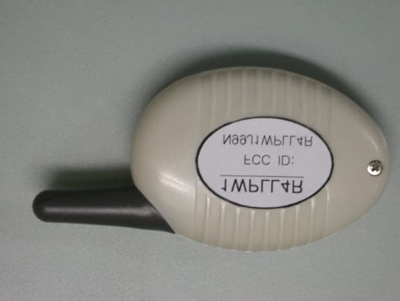
N99J1WPLL4R
Jul 13, 2003Model 1WPLL4R - hand held transmitter
Equipment Class
DXT - Part 15 Low Power Transceiver, Rx Verified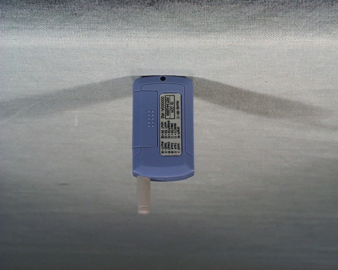
N99J447RS
Feb 13, 2002Model 2WFMRS- hand-held transceiver
Equipment Class
DSC - Part 15 Security/Remote Control Transmitter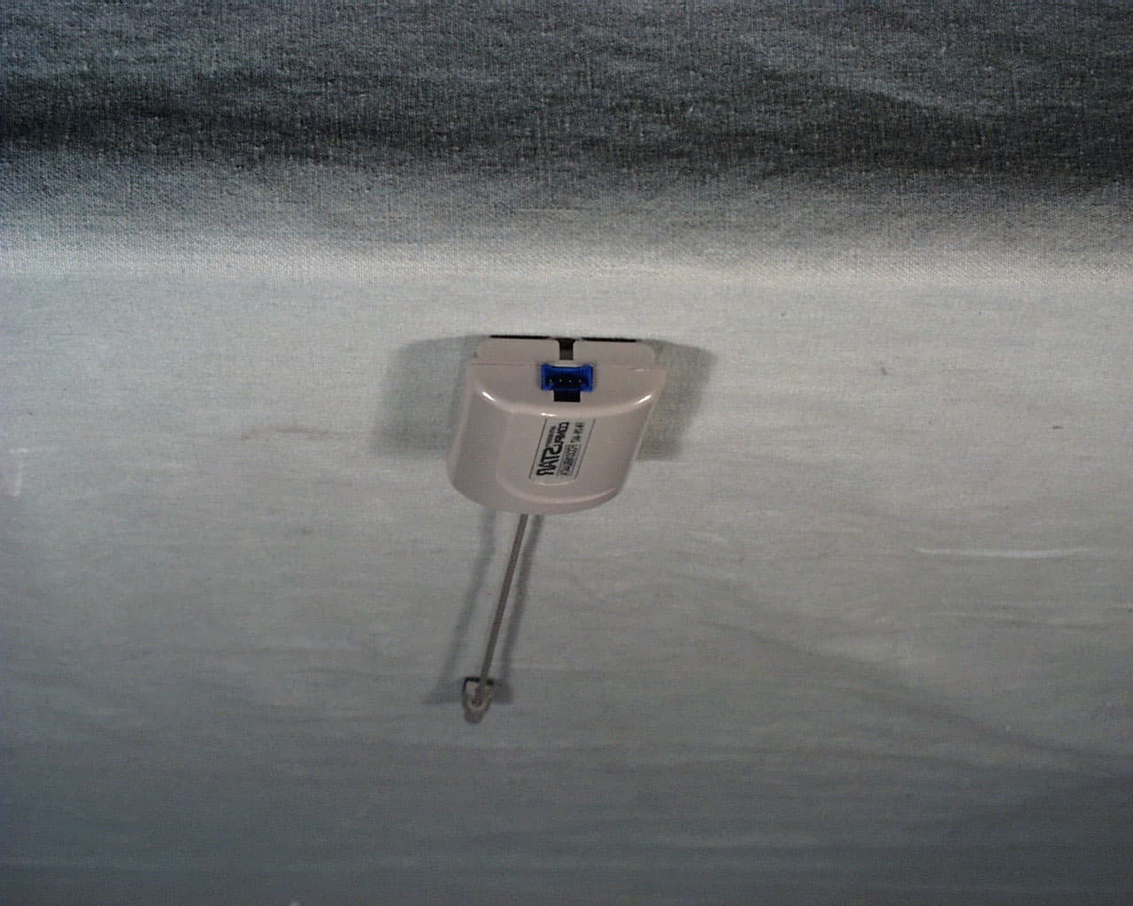
N99J447A
Feb 12, 2002Model ANT2W - car mount transceiver
Equipment Class
DSC - Part 15 Security/Remote Control Transmitter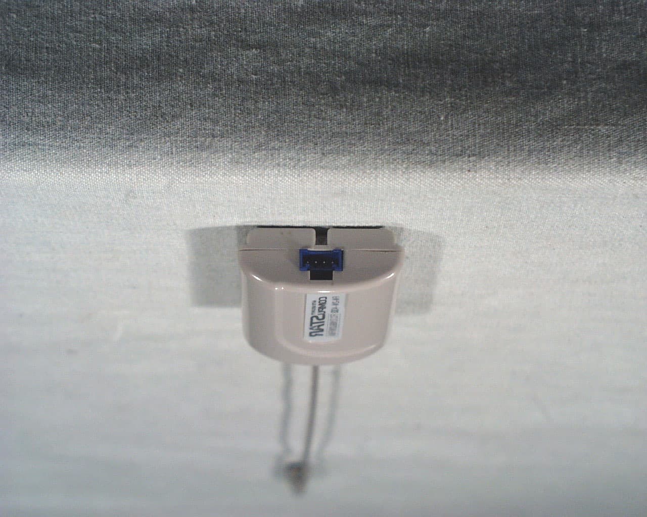
N99JANT2W
Dec 04, 2001Car mounted remote starter and alarm
Equipment Class
DSC - Part 15 Security/Remote Control Transmitter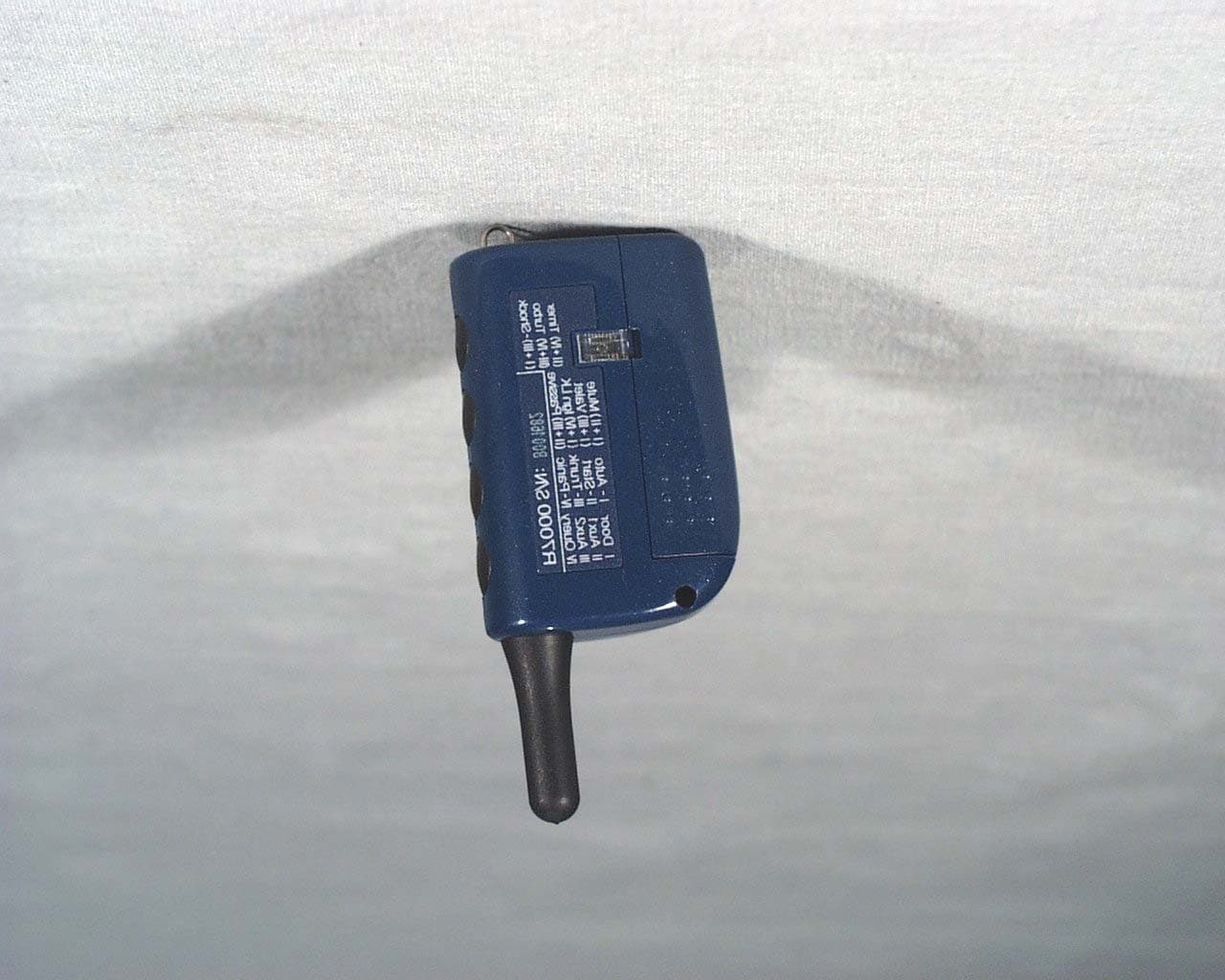
N99J2WFMR
Dec 04, 2001Remote portion of car starting and alarm system
Equipment Class
DSC - Part 15 Security/Remote Control Transmitter