N99SSTRhandheld tranmitter - automobile starter
Firstech, Inc.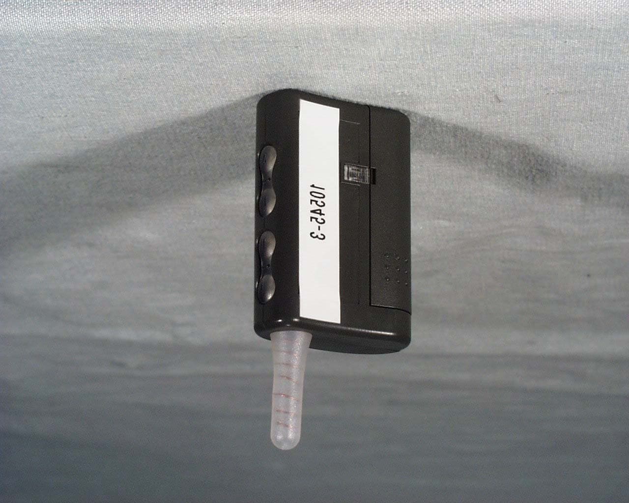
Click to zoom
Application Details
- Equipment Class
- DSS - Part 15 Spread Spectrum Transmitter
- Date of Grant
- Aug 17, 2001
- Application Purpose
- Original Equipment
- Date of Application
- Aug 17, 2001
- Equipment Note
- handheld tranmitter - automobile starter
- Frequency Range
- 907.20000000 - 909.90000000
- Company
- Firstech, Inc.
- Country
- United States
Documents & Files
Document Text
Text extracted from the exhibit documents filed with the FCC. Open a document above to read the original.
Users Manual
By Firstech, Inc INSTALLATION AND USER’S GUIDE website: www.compustar.org © 2001 Firstech, Inc. Page 1 TABLE OF CONTENTS FCC/ID Notice............................................................................. 2 Remote-Pager ................................................................................. 3 Remote-Pager Button Functions....................................................... 4 Using Your System............................................................................ 5 Alarm Mode.................................................................................. 5 Dual Stage Shock Sensor............................................................... 6 Panic Mode.................................................................................. 7 Auto-start Function........................................................................ 8 Query Function............................................................................. 8 CompuGLO Back-Light Mode ........................................................ 8 Trunk Release ............................................................................. 8 Reservation Mode (Manual Transmissiononly) 8 Safety Shutdown Features............................................................... 10 Valet Mode................................................................................... 10 Timer Start Mode...........................................................................10 Additional Features............................................................................ 10 Optional Auxiliary 1 & Auxiliary 2....................................................... 10 Installation.................................... ................................. 12 © 2001 Firstech, Inc. Page 2 FCC/ID Notice This device complies with Part 15 of the FCC Rules. Operation is subject to the following two conditions: (1) This device may not cause harmful interference, and (2) This device must accept any interference received, including interference that may cause undesired operation. CAUTION: Changes or modifications not expressly approved by the party responsible for compliance could void the user’s authority to operate this device. This equipment has been tested and found to comply with the limits for a Class B digital device, pursuant to Part 15 of the FCC Rules. These limits are designed to provide reasonable protection against harmful interference in a residential installation. This equipment generates, uses and can radiate radio frequency energy and, if not installed and used in accordance with the instructions, may cause harmful interference to radio communications. However, there is no guarantee that interference will not occur in a particular installation. If this equipment does cause harmful interference to radio or television reception, which can be determined by turning the equipment off and on, the user is encouraged to try to correct the interference by one or more of the following measures: Reorient or relocate the receiving antenna. Increase the separation between the equipment and receiver. Connect the equipment into an outlet on a circuit different from that to which the receiver is connected. Consult your Authorized CompuStar dealer. REMOTE-PAGER © 2001 Firstech, Inc. Page 3 This 5 channel transmitter that allows you to activate multiple functions by pressing a combination of 4 buttons on the unit in order to transmit signals. Press Buttons (II+III) for a ½ second to make your remote-pager mute. A vibration icon will appear continuously on the upper left-hand corner of your CompuGLO LCD indicating that you are in remote-pager mute mode . Remote-Pager CompuGLO color LCD The remote-pager comes with CompuGLO which is a unique color LCD display that visually tells the vehicle owner the security status of your car at all times. There are differing icons that will appear on your CompuGLO LCD indicating what your vehicle is currently doing. Remote-Pager Button Functions The user can activate differing functions of CompuStar 2WSSR system by pressing one or two buttons simultaneously [ex. (I+IV) ] located on the antenna side of your CompuStar remote-pager. Channel Button Press for Function Factory Setting 1. I 1/2 sec Alarm Mode - on/off VPS - on/off 2. II 1/2 sec Auxiliary Option 1 © 2001 Firstech, Inc. Page 4 3. III 1/2 sec Auxiliary Option 2 4. IV 1/2 sec Query Function 5. I - 2 sec Same as pressing ½ secs. 6. II - 2 sec Auto-start Function - on/off 7. III - 2 sec Trunk Release - on/off 8. IV - 2 sec Panic Off 9. (I+II) 1/2 sec Car Siren (mute) - on/off On 10. (I+III) 1/2 sec Valet Mode – on/off Off 11. (I+IV) 1/2 sec Ignition Lock - on/off Off 12. (II+III) 1/2 sec Passive Lock - on/off Off 13. (II+IV) 1/2 sec Timer Start Mode - on/off Off 14. (III+IV) 1/2 sec Turbo Mode - on/off Off 15 (I+III) - 2 sec Shock Sensor – on/off On 16 (II+III) - 2sec Remote-Pager Beep (mute) - on/off On 17. (I+II) - 2 sec Programming Menu 1 18. (I+III) - 2 sec Programming Menu 2 Note: ( ) means simultaneously pressing the buttons Note: ( ) – means simultaneously pressing the buttons for 2 seconds. USING YOUR SYSTEM Your CompuStar 2WSSR system has many different modes and functions that can be activated by using your remote-pager unit. Alarm Mode You can arm or disarm alarm mode by pressing Button I for a ½ second or 2 seconds. A bolted padlock icon will appear on your CompuGLO LCD indicating that your car is armed and a lock icon will appear showing that your car doors are locked. Also, your car will chirp when you arm or disarm your car. © 2001 Firstech, Inc. Page 5 Press Buttons (I+II) for a ½ second to make your car siren mute when arming or disarming your vehicle. A car siren icon will disappear on the bottom left-hand corner of your CompuGLO LCD indicating that you are in car siren mute mode . Keep in mind that your car siren will still activate for all other modes (i.e. panic, alarm, shock sensor) regardless of whether or not your car sire…
Text truncated - open the document above for the full version.
Cover Letter(s)
801 E. 82nd St., Unit 1, Anchorage, Alaska 99518 USA Phone (907) 563-8648 ~ Fax (907) 563-8642 [email protected] www.compustar.org CONFIDENTIALITY REQUEST LETTER FEDERAL COMMUNICATIONS COMMISSION 7435 Oakland Mills Road Columbia, MD 21046 Subject: Request for Confidentiality FCC ID: N99 STTR To Whom it May Concern: In accordance with §0.459 of CFR 47, Firstech, Inc. requests confidentiality for the following items: 1. Block Diagram 2. Schematic Diagrams 3. Theory of Operation These items contain detailed system and equipment description and related information about the product which Firstech, Inc. considers to be proprietary, confidential and a custom design which otherwise would not be released to the general public. Since this design is a basis from which future technological products will evolve, Firstech, Inc. also feels that this information would be of benefit to its competitors, and that the disclosure of the information in these exhibits would give our competitors an unfair advantage in the market. Best regards, Ken H. Lee Design Engineer
External Photos
COMMUNICATION CERTIFICATION LABORATORY TEST REPORT: 73-7473 FCC ID: N99SSTR Page 47 OF 53 Front View Of The SSTR COMMUNICATION CERTIFICATION LABORATORY TEST REPORT: 73-7473 FCC ID: N99SSTR Page 48 OF 53 Back View Of The SSTR
ID Label/Location Info
FC C I D : N9 9 S S T R R e m o t e Bot to m V i e w F C C L abe l Loc a t ion FC C I D : N 9 9 SSTR P r opo s ed L a b e l Loc a t io n
Internal Photos
COMMUNICATION CERTIFICATION LABORATORY TEST REPORT: 73-7473 FCC ID: N99SSTR Page 49 OF 53 Inside View Of The SSTR COMMUNICATION CERTIFICATION LABORATORY TEST REPORT: 73-7473 FCC ID: N99SSTR Page 50 OF 53 Front View of the LCD Board COMMUNICATION CERTIFICATION LABORATORY TEST REPORT: 73-7473 FCC ID: N99SSTR Page 51 OF 53 Back View of the LCD Board COMMUNICATION CERTIFICATION LABORATORY TEST REPORT: 73-7473 FCC ID: N99SSTR Page 52 OF 53 Front View of the Daughter Board COMMUNICATION CERTIFICATION LABORATORY TEST REPORT: 73-7473 FCC ID: N99SSTR Page 53 OF 53 Back View of the Daughter Board
RF Exposure Info
Portable Spread Spectrum transmitter for authoriztion under §15.247. The transmitter operates in a single frequency band and it is not a module that operates as part of another product or device. The device does not operate in conjunction with another transmitter and its antenna is not co-located with other antennas. The device and its antenna may operate at less than 2.5 cm from a person’s body. The peak conducted with peak radiated (EIRP) output power are less than 25 mW. The device operates only in the 900 MHz band. Peak conducted output power is 7.9mW, and the antenna gain is 0 dBi. The antenna is directly attached to the device, no installation instructions are needed. The device is not a modular transmitter. Given these considerations, no instructions to the user are needed in the manual.
Test Report
TEST REPORT FROM: COMMUNICATION CERTIFICATION LABORATORY 1940 W. Alexander Street Salt Lake City, Utah 84119-2039 Type of Report: Certification TEST OF: SSTR FCC ID: N99SSTR To FCC PART 15.247, Subpart C Test Report Serial No: 73-7473 Applicant: Firstech Inc. 801 Eeast 82 nd Avenue Unit #1 Anchorage, AK 99518 Date(s) of Test: June 19 - 20, 2001 Issue Date: August 1, 2001 Equipment Receipt Date: June 19, 2001 COMMUNICATION CERTIFICATION LABORATORY TEST REPORT: 73-7473 FCC ID: N99SSTR Page 1 OF 53 CERTIFICATION OF ENGINEERING REPORT This report has been prepared by Communication Certification Laboratory to determine compliance of the device described below with the requirements of FCC PART 15.247, Subpart C. This report may be reproduced in full, partial reproduction may only be made with the written consent of the laboratory. The results in this report apply only to the sample tested. - Applicant: Firstech Inc. - Manufacturer’s: YOUNGSHIN ELECTRONICS CO., LTD. - Brand Name: CompuStar - Model Number: SSTR - FCC ID: N99SSTR On this 1 st day of August 2001, I, individually, and for Communication Certification Laboratory, certify that the statements made in this engineering report are true, complete, and correct to the best of my knowledge, and are made in good faith. COMMUNICATION CERTIFICATION LABORATORY Tested by: Kirk P. Thomas Project Engineer COMMUNICATION CERTIFICATION LABORATORY TEST REPORT: 73-7473 FCC ID: N99SSTR Page 2 OF 53 TABLE OF CONTENTS PAGE SECTION 1. CLIENT INFORMATION AND MANUFACTURER:................3 SECTION 2. EQUIPMENT UNDER TEST (EUT)..........................4 SECTION 3. TEST SPECIFICATION, METHODS & PROCEDURES............6 SECTION 4. OPERATION OF EUT DURING TESTING....................12 SECTION 5. SUMMARY OF TEST RESULTS:...........................13 SECTION 6. MEASUREMENTS, EXAMINATIONS AND DERIVED RESULTS:....14 APPENDIX 1 TEST PROCEDURES AND TEST EQUIPMENT..................37 A PPENDIX 2 PHOTOGRAPHS.........................................45 COMMUNICATION CERTIFICATION LABORATORY TEST REPORT: 73-7473 FCC ID: N99SSTR Page 3 OF 53 SECTION 1. CLIENT INFORMATION AND MANUFACTURER: 1.1 Client Information: Company Name: Firstech Inc. 801 Eeast 82 nd Avenue Unit #1 Anchorage, AK 99518 Contact Name: Jason Lee Title: President 1.2 Manufacturer: Company Name: YOUNGSHIN ELECTRONICS CO., LTD. 4FL Hirun Town Bldg 536-3. Unhaeng-Dong. Sihung, Kyungki-Do, KOREA 429-060 Contact Name: Young T1 Change Title: President COMMUNICATION CERTIFICATION LABORATORY TEST REPORT: 73-7473 FCC ID: N99SSTR Page 4 OF 53 SECTION 2. EQUIPMENT UNDER TEST (EUT) 2.1 Identification of EUT: Trade Name: Firstech Inc. Model Name or Number: SSTR Serial Number: N/A Options Fitted: None Country of Manufacture: Korea 2.2 Description of EUT: The SSTR is a remote automobile pager. The SSTR allows for remote monitoring and control of an automobiles alarm system, doors, lights, and engine starter. The SSTR transceiver operates in the 900 MHz range. This report covers the transmitter only. The receiver is covered under a separate verification report. 2.3 Modification Incorporated/Special Accessories on EUT: There were no modifications or special accessories required to comply with the specification. 2.4 EUT and Support Equipment: The FCC ID numbers for both the EUT and support equipment used during the test (including inserted cards) are listed below: Brand Name Model Number FCC ID Number Description Name of Interface Ports / Interface Cables BN: Firstech Inc. (1) MN: SSTR N99SSTR Transceiver See Section 2.5. Note: (1) EUT. (2) Interface port connected to EUT (See Section 2.5) (3) Mouse cable permanently attached. The support equipment listed above was not modified in order to achieve compliance with this standard. COMMUNICATION CERTIFICATION LABORATORY TEST REPORT: 73-7473 FCC ID: N99SSTR Page 5 OF 53 2.5 Interface Ports on EUT: Name of Ports No. of Ports Fitted to EUT. Cable Descriptions/Length Antenna 1 Soldered directly to EUT COMMUNICATION CERTIFICATION LABORATORY TEST REPORT: 73-7473 FCC ID: N99SSTR Page 6 OF 53 SECTION 3. TEST SPECIFICATION, METHODS & PROCEDURES 3.1 Test Specification: Title: FCC PART 15.247, Subpart C (47 CFR 15). Limits and methods of measurement of radio interference characteristics of radio frequency devices. Operation within the bands 902-928 MHz, 2400-2483.5 MHz and 5725- 5850 MHz. Purpose of Test: The tests were performed to demonstrate Initial compliance. 3.2 Methods & Procedures: 3.2.1 § 15.247 (a) Operation under the provisions of this section is limited to frequency hopping and direct sequence spread spectrum intentional radiators that comply with the following provisions: (1) Frequency hopping systems shall have hopping channel carrier frequencies separated by a minimum of 25 kHz or the 20 dB bandwidth of the hopping channel, whichever is greater. The system shall hop to channel frequencies that are selected at the system hopping rate from a pseudorandomly ordered list of hopping frequencies. Each frequency must be used equally on the average by each transmitter. The system receivers shall have input bandwidths that match the hopping channel bandwidths of their corresponding transmitters and shall shift frequencies in synchronization with the transmitted signals. (i) For frequency hopping systems operating in the 902–928 MHz band: if the 20 dB bandwidth of the hopping channel is less than 250 kHz, the system shall use at least 50 hopping frequencies and the average time of occupancy on any frequency shall not be greater than 0.4 seconds within a 20 second period; if the 20 dB bandwidth of the hopping channel is 250 kHz or greater, the system shall use at least 25 hopping frequencies and the average time of occupancy on any frequency shall not be greater than 0.4 seconds within a 10 second period. The maximum allowed 20 dB bandwidth of the hopping channel is 500 kHz. (ii) Frequency hopping systems operating in the 2400–2483.5 MHz and 5725– 5850 MHz bands shall use at least 75 hop…
Text truncated - open the document above for the full version.
Test Setup Photos
COMMUNICATION CERTIFICATION LABORATORY TEST REPORT: 73-7473 FCC ID: N99SSTR Page 45 OF 53 APPENDIX 2 PHOTOGRAPHS Front View of Radiated Test Setup COMMUNICATION CERTIFICATION LABORATORY TEST REPORT: 73-7473 FCC ID: N99SSTR Page 46 OF 53 Back View Of Radiated Test Setup
Contact Information
Applicant
Jason Lee(President)
Technical Contact
Firstech Inc.Jason Lee
[email protected]907 222 3804
801 Eeast 82nd Avenue Unit #1 · Anchorage,, Alaska · United States
Non-Technical Contact
Firstech Inc.Jason Lee
[email protected]907 222 3804
Test Firm
Communication Certification Lab.Scott Earl
Technical Specifications
| # | Rule Parts | Frequency Range | Power Output |
|---|---|---|---|
| 1 | 15C | 907.2 MHz - 909.9 MHz | 7.90 mW |
Other Applications from Firstech, Inc.
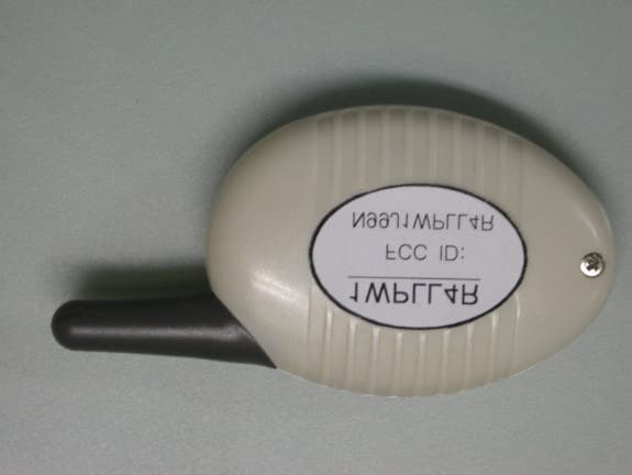
N99J1WPLL4R
Jul 13, 2003Model 1WPLL4R - hand held transmitter
Equipment Class
DXT - Part 15 Low Power Transceiver, Rx Verified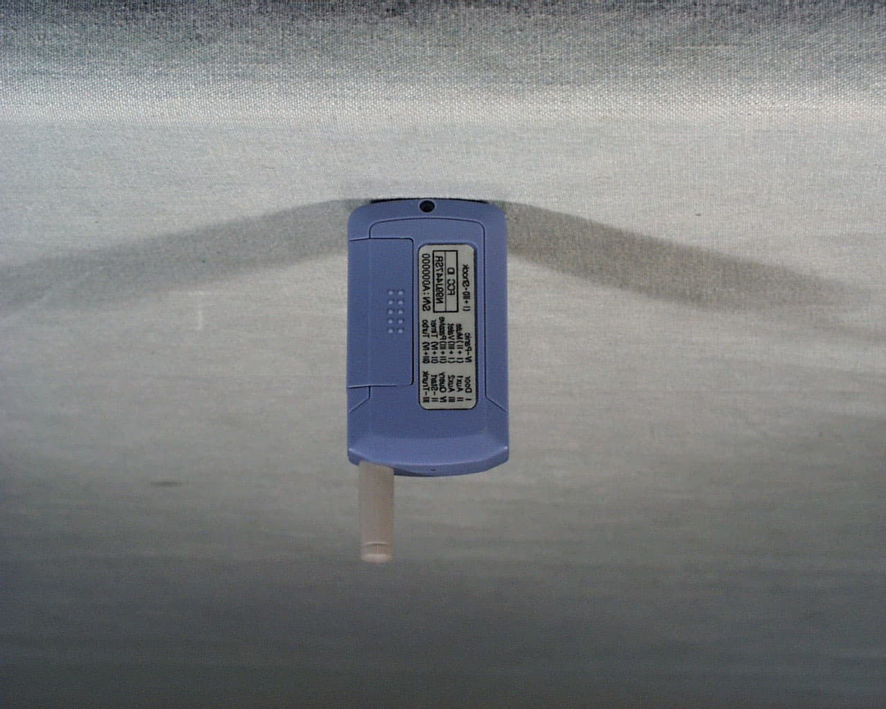
N99J447RS
Feb 13, 2002Model 2WFMRS- hand-held transceiver
Equipment Class
DSC - Part 15 Security/Remote Control Transmitter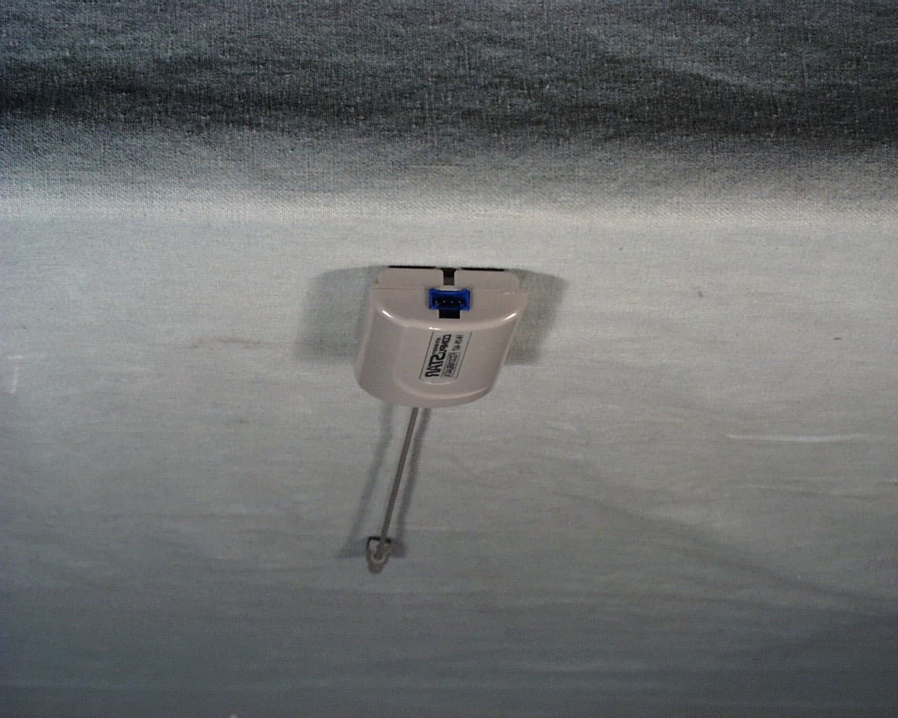
N99J447A
Feb 12, 2002Model ANT2W - car mount transceiver
Equipment Class
DSC - Part 15 Security/Remote Control Transmitter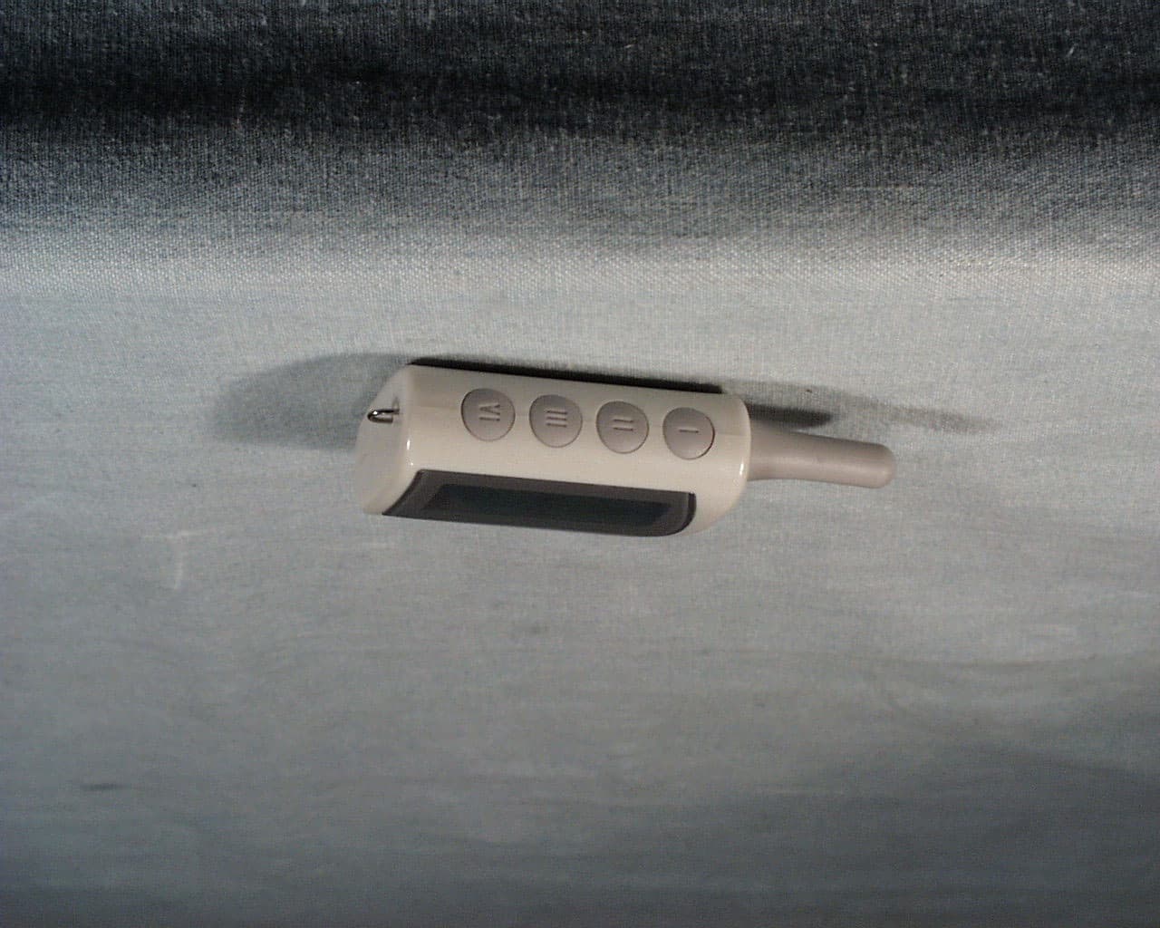
N99J447R
Feb 12, 2002Model 2WFMR - hand-held transceiver
Equipment Class
DSC - Part 15 Security/Remote Control Transmitter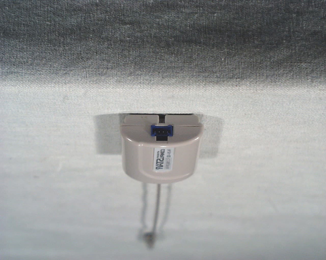
N99JANT2W
Dec 04, 2001Car mounted remote starter and alarm
Equipment Class
DSC - Part 15 Security/Remote Control Transmitter