N9KGTOMMKPDControl Keypad
Smart Technologies & Investment Ltd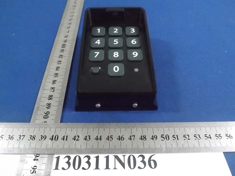
Click to zoom
Application Details
- Equipment Class
- DSR - Part 15 Remote Control/Security Device Transceiver
- Date of Grant
- Jun 04, 2013
- Application Purpose
- Original Equipment
- Date of Application
- Jun 04, 2013
- Equipment Note
- Control Keypad
- Frequency Range
- 318.00000000 - 318.00000000
- Country
- Hong Kong
Documents & Files
Document Text
Text extracted from the exhibit documents filed with the FCC. Open a document above to read the original.
Users Manual
2 3 Table of Contents Keypad Features ...................................................................................................Cover Keypad Description ......................................................................................................3 Installing Batteries ........................................................................................................3 “Learn” Transmitter Code ..............................................................................................3 Program the Keypad ....................................................................................................4 Normal Keypad Operation ...........................................................................................5 Keying Indication Summary .........................................................................................5 Warranty Information .....................................................................................................6 Notes .............................................................................................................................7 Factory Code Your Master Code Additional Codes (Up to 25): 1234 Date of Purchase: ________________________________ Place of Purchase: _________________________________________________________________ Please record the following information. Be sure to keep all receipts for proof of purchase. Refer to this information when calling GTO for service or assistance with your keypad. FOR YOUR RECORDS 2 3 Keypad Description Installing Batteries Step 1: Remove the two screws from the bottom of the keypad (FIG. 1) and separate the keypad from its housing. Step 2: Install 3 AA batteries (not included) (FIG. 2). + – + – + – STATUS Light: The LED will blink once when any key is pressed and provides visual feedback during access code programming. PROGRAM Button: Use for/during program process. Keypad - Front Battery Holder: 3 AA batteries are required to power the keypad (not included). RESET Button: Pressing this button for 2 seconds will reprogram keypad to factory settings. All codes are deleted. Default master code is 1234. Keypad - Inside Installation of the Keypad NOTE: The distance from the keypad to the opener’s receiver should not exceed 50 ft. Always test the keypad range before permanently mounting it. Step 1: Mount the keypad cover using the screws provided. (FIG. 3) Step 2: Slide the keypad into cover and secure with the screws. (FIG. 4) NOTE: If you have not changed your opener’s transmitter code from the factory setting, see the “Setting Your Personal Transmitter Code” section in the gate opener’s manual then “Learn” the transmitter code into the keypad. See “Learn Transmitter Code” section below. ❶ Press and release the PROGRAM button. ❷ Enter the Master Code then press and release the PROGRAM button. ❸ Enter 0,5 then press and release the PROGRAM button. ❹ Press and hold the transmitter button while holding the transmitter to the right side of the keypad between the 3 and the 6 as shown. ❺ The keypad will beep 3 times to confirm that the transmitter is successfully “Learned.” Release the transmitter button at this time. 1 2 3 4 5 8 0 9 7 6 1 2 3 4 5 8 0 9 7 6 FIG. 2 FIG. 1 FIG. 3 FIG. 4 ① IMPORTANT: Make sure the transmitter operates the gate opener. Turn off the gate opener so that there is no unintended operation of the gate during the learning process. “Learn” Transmitter Code ②③ ⑤④ IMPORTANT: Transmitter must be placed exactly as shown against the right side of the keypad between the 3 and the 6 in order for the “learning” process to work correctly. Press & Release Program Button. Enter Master Code, Press & Release Program Button again. Enter 0 5 Press & Release Program Button again. Press and hold the transmitter button holding it to right side of keypad between the 3 and the 6. Keypad will beep 3 times. Release the transmitter button. 4 5 Program New Master Code 1. Press and Release Program Button: 2. Enter current Master Code: (example: the factory default Master Code) 3. Press and Release Program Button: 4. Enter the Function Code: 5. Press and Release Program Button: 6. Enter the new Master Code: 7. Press and Release Program Button: 8. Enter the new Master Code again: 9. Press and Release Program Button: Program Button Status Light = Your 4-digit code. Program the Keypad • A Master Code is needed to add, remove, or program Entry Codes. • Factory default Master Code is “1234.” • Keypad can only enter “program” mode from “idle” mode. • Keypad will beep three times before going into “idle” mode (more than 10 seconds between key presses). Add New Entry Code 1. 2. Master Code 3. 4. Function Code 5. 6. New Entry Code 7. Delete Entry Code 1. 2. Master Code 3. 4. Function Code 5. 6. Code to be deleted 7. Delete All Entry Codes 1. 2. Master Code 3. 4. Function Code 5. Add Temporary Entry Code *In step 4, you will need to enter a number from 1 through 7 to indicate the number of days until the Entry Code expires. 1. 2. Master Code 3. 4. Function Code & # of days Code will be active* 5. 6. Temporary Entry Code 7. Programming Confirmed: Keypad will beep 3 times. Error Message: Status light will flash rapidly, error tone will sound for 1 second and keypad will return to “idle” mode (changes not saved). • Entry Code is not 4 digits. • New Master Codes don’t match (“Program New Master Code”). • Memory is full (already 25 codes). • No matching code is found (“Delete Entry Code”). 4 5 Normal Keypad Operation: • If the user enters a 4-digit code that is matched to one of the 25 stored codes. The STATUS light should blink rapidly indicating that it is sending command to operator. • No more than 20 key presses are allowed to obtain the 4-digit entry code. Example: 1234 is one of the codes stored in one of the memory location. The user can enter “x1234” or “xxxxxxxxxxxxxxxx1234” and the gate should be activated (x is any key). If more than 20 key presses is entered without matching one of the…
Text truncated - open the document above for the full version.
External Photos
Bureau Veritas Shenzhen Co., Ltd. Dongguan Branch No. 34, Chenwulu Section, Guantai Rd., Houjie Town, Dongguan City, Guangdong 523942, China Tel.: +86 769 8593 5656 Fax: +86 769 8593 1080 Email: [email protected] Page 1 of 3 Report Version 1 Reference No.: 130311N036 PHOTOGRAPHS OF THE EUT Bureau Veritas Shenzhen Co., Ltd. Dongguan Branch No. 34, Chenwulu Section, Guantai Rd., Houjie Town, Dongguan City, Guangdong 523942, China Tel.: +86 769 8593 5656 Fax: +86 769 8593 1080 Email: [email protected] Page 2 of 3 Report Version 1 Reference No.: 130311N036 Bureau Veritas Shenzhen Co., Ltd. Dongguan Branch No. 34, Chenwulu Section, Guantai Rd., Houjie Town, Dongguan City, Guangdong 523942, China Tel.: +86 769 8593 5656 Fax: +86 769 8593 1080 Email: [email protected] Page 3 of 3 Report Version 1 Reference No.: 130311N036
ID Label/Location Info
Label location statement 1. The battery cover should be called Lower Case, please see the following figure as stated: The purpose of the Middle Case is used to fix the battery box and the PCB, and the Lower Case is the last action for assembling the units. It's become a complete product once all the components assembled together. 2. If the label stick in the Middle Case area, the label will block the buzzer & reset key (please see the following figure) 3. So that label position as below stated is the most appropriate.
ID Label/Location Info
ERP机型:FM137 Designed:OuyanniDate:2013-03-22 描述: ERP P/N: REV:A FM137 FCC label, 80G45*20MM, FCC ID:N9KGTOMMKPD
Internal Photos
Bureau Veritas Shenzhen Co., Ltd. Dongguan Branch No. 34, Chenwulu Section, Guantai Rd., Houjie Town, Dongguan City, Guangdong 523942, China Tel.: +86 769 8593 5656 Fax: +86 769 8593 1080 Email: [email protected] Page 1 of 2 Report Version 1 Reference No.: 130311N036 PHOTOGRAPHS OF THE EUT Bureau Veritas Shenzhen Co., Ltd. Dongguan Branch No. 34, Chenwulu Section, Guantai Rd., Houjie Town, Dongguan City, Guangdong 523942, China Tel.: +86 769 8593 5656 Fax: +86 769 8593 1080 Email: [email protected] Page 2 of 2 Report Version 1 Reference No.: 130311N036 ANT
Test Report
Bureau Veritas Shenzhen Co., Ltd. Dongguan Branch No. 34, Chenwulu Section, Guantai Rd., Houjie Town, Dongguan City, Guangdong 523942, China Tel: +86 769 8593 5656 Fax: +86 769 8593 1080 Email: [email protected] Page 1 of 25 Report Version 1 Test Report No.: RF130311N036 TEST REPORT Applicant Smart Technologies & Investment Ltd. Address: Units C & D, 18/F Spectrum Tower, No. 53 Hung To Road, Kwun Tong, Kowloon, Hong Kong Manufacturer or Supplier Smart Electronic Industrial (Dong Guan) Co., Ltd. Address Qing Long Road, Long Jian Tian-Cun, Huang Jiang-Zhen, Dong Guan, Guang Dong, China Product: KeyPad Control Brand Name: GTO MIGHTY MULE , GTO / ACCESS - GTO / PRO Model: MMKPD Additional Model & Model Difference: FM137-G4, See section 3.1 NOTE Date of tests: Mar. 12, 2013~ Mar. 20, 2013 the tests have been carried out according to the requirements of the following standards: FCC Part 15, Subpart C (Section 15.231a) CONCLUSION: The submitted sample was found to COMPLY with the test requirement Prepared by Glyn He Project Engineer / EMC Department Approved by Sam Tung Manager / EMC Department Date: Mar. 20, 2013 This report is for your exclusive use. Any copying or replication of this report to or for any other person or entity, or use of our name or trademark, is permitted only with our prior written permission. This report sets forth our findings solely with respect to the test samples identified herein. The results set forth in this report are not indicative or representative of the quality or characteristics of the lot from which a test sample was taken or any similar or identical product unless specifically and expressly noted. Our report includes all of the tests requested by you and the results thereof based upon the information that you provided to us. You have 60 days from date of issuance of this report to notify us of any material error or omission caused by our negligence, provided, however, that such notice shall be in writing and shall specifically address the issue you wish to raise. A failure to raise such issue within the prescribed time shall constitute your unqualified acceptance of the completeness of this report, the tests conducted and the correctness of the report contents. Unless specific mention, the uncertainty of measurement has been explicitly taken into account to declare the compliance or non-compliance to the specification Bureau Veritas Shenzhen Co., Ltd. Dongguan Branch No. 34, Chenwulu Section, Guantai Rd., Houjie Town, Dongguan City, Guangdong 523942, China Tel: +86 769 8593 5656 Fax: +86 769 8593 1080 Email: [email protected] Page 2 of 25 Report Version 1 Test Report No.: RF130311N036 TABLE OF CONTENTS RELEASE CONTROL RECORD ............................................................................................................ 4 1 SUMMARY OF TEST RESULTS ..................................................................................................... 5 2 MEASUREMENT UNCERTAINTY .................................................................................................. 5 3 GENERAL INFORMATION .............................................................................................................. 6 3.1 GENERAL DESCRIPTION OF EUT........................................................................................... 6 3.2 DESCRIPTION OF TEST MODES............................................................................................. 6 3.3 TEST MODE APPLICABILITY AND TESTED CHANNEL DETAIL ............................................ 7 3.4 GENERAL DESCRIPTION OF APPLIED STANDARDS............................................................ 9 3.5 DESCRIPTION OF SUPPORT UNITS....................................................................................... 9 4. TEST TYPES AND RESULTS ....................................................................................................... 10 4.1 RADIATED EMISSION MEASUREMENT ................................................................................ 10 4.1.1 LIMITS OF RADIATED EMISSION MEASUREMENT..................................................... 10 4.1.2 TEST INSTRUMENTS......................................................................................................11 4.1.3 TEST PROCEDURES ..................................................................................................... 12 4.1.4 DEVIATION FROM TEST STANDARD ........................................................................... 12 4.1.5 TEST SETUP................................................................................................................... 13 4.1.6 EUT OPERATING CONDITIONS .................................................................................... 13 4.1.7 TEST RESULTS .............................................................................................................. 14 4.2 20dB BANDWIDTH MEASUREMENT ..................................................................................... 18 4.2.1 LIMITS OF 20dB BANDWIDTH MEASUREMENT.......................................................... 18 4.2.2 TEST INSTRUMENTS..................................................................................................... 18 4.2.3 TEST PROCEDURE........................................................................................................ 19 4.2.4 DEVIATION FROM TEST STANDARD ........................................................................... 19 4.2.5 TEST SETUP................................................................................................................... 19 4.2.6 EUT OPERATING CONDITIONS .................................................................................... 19 4.2.7 TEST RESULTS .............................................................................................................. 20 4.3 DEACTIVATION TEST ............................................................…
Text truncated - open the document above for the full version.
Test Setup Photos
1 Set-up for radiated emission test <Frequency Range 30MHz~1GHz> <Frequency Range above1GHz>
Contact Information
Applicant
Ling Li(Sales Admin. Manager)
Test Firm
Bureau Veritas Shenzhen Co., Ltd. Dongguan BranchAlec Hu
Technical Specifications
| # | Rule Parts | Frequency Range | Power Output |
|---|---|---|---|
| 1 | 15.231 | 318 MHz - 318 MHz | - |
Other Applications from Smart Technologies & Investment Ltd
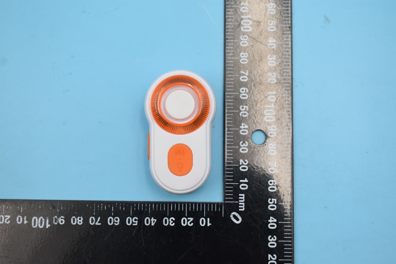
N9KSMARTMD328E
Jan 11, 2020Bluetooth Personal Alarm
Equipment Class
DTS - Digital Transmission System
N9KSMARTMA0136
Dec 10, 2015MaceAlert Smart Panel
Equipment Class
DTS - Digital Transmission System
N9KSMARMA136TX
Dec 10, 2015Keychain Remote Control
Equipment Class
DSC - Part 15 Security/Remote Control Transmitter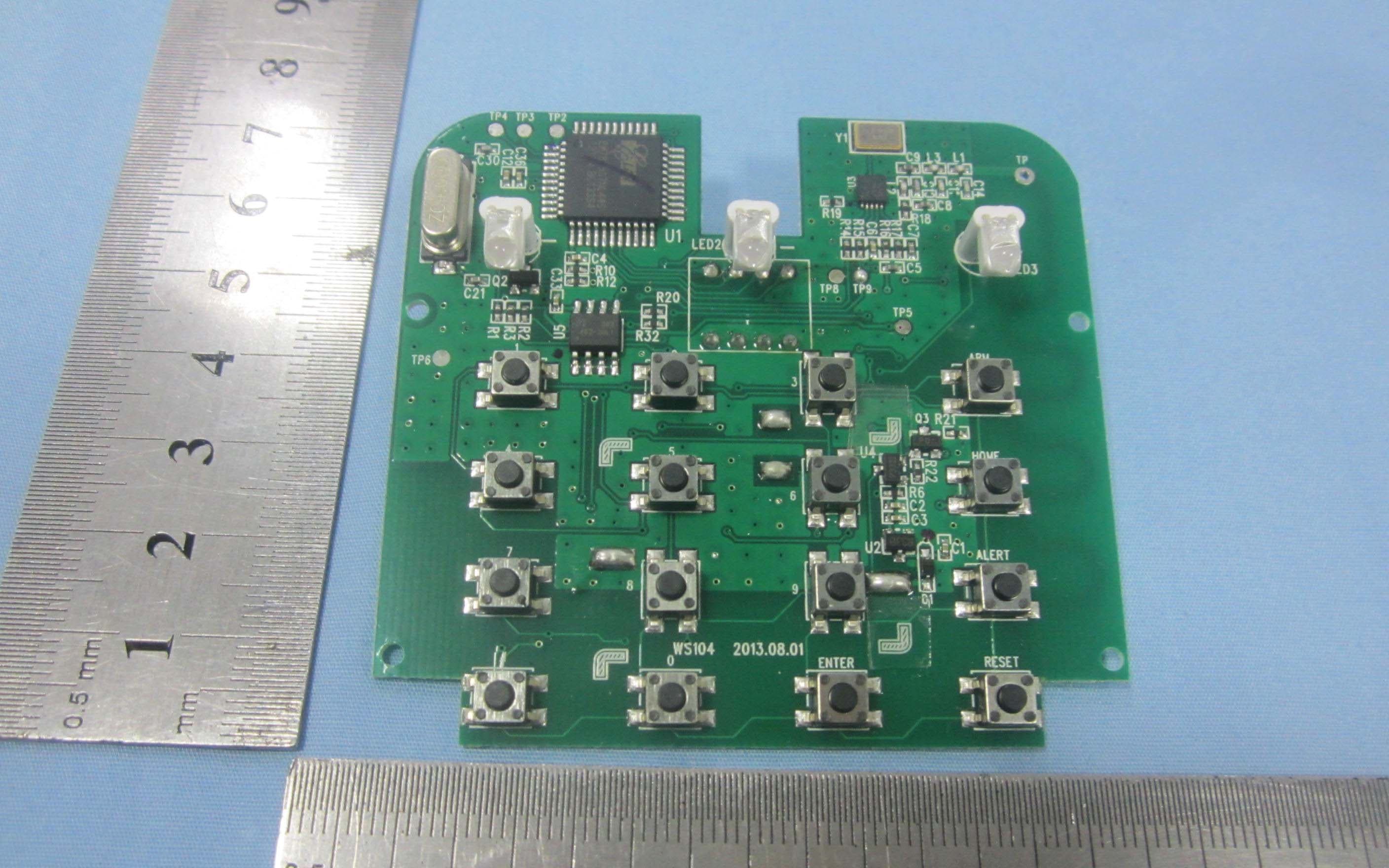
N9KSMARTWS104
Nov 14, 2013KEY PAD CONTROL
Equipment Class
DSC - Part 15 Security/Remote Control Transmitter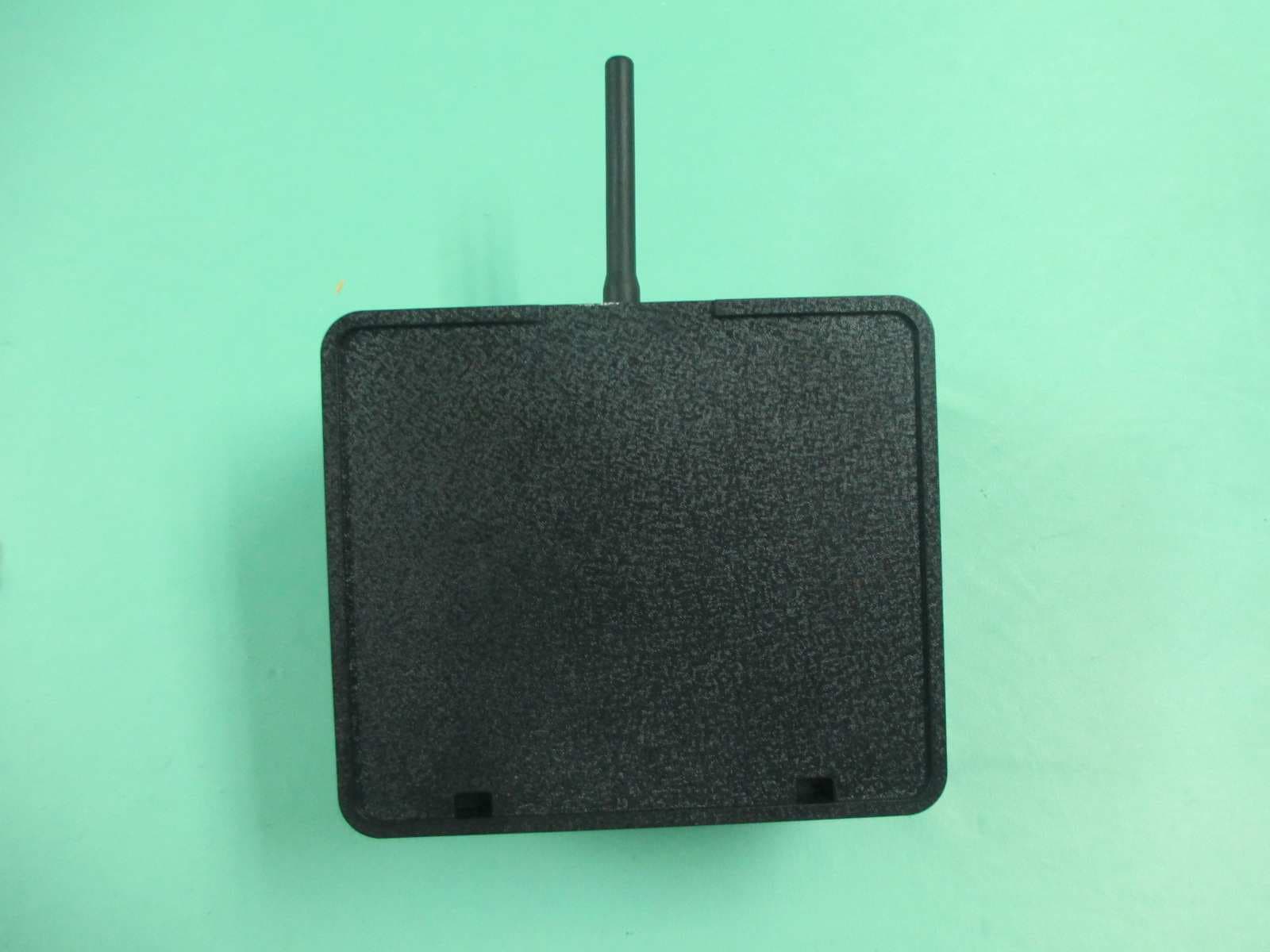
N9KGTOF3100
Jul 08, 2013GTO ACCESS WIRELESS ESTATE INTERCOM
Equipment Class
DXX - Part 15 Low Power Communication Device Transmitter