N9KSMARTECDO100TXGate Door Opener
Smart Technologies & Investment Ltd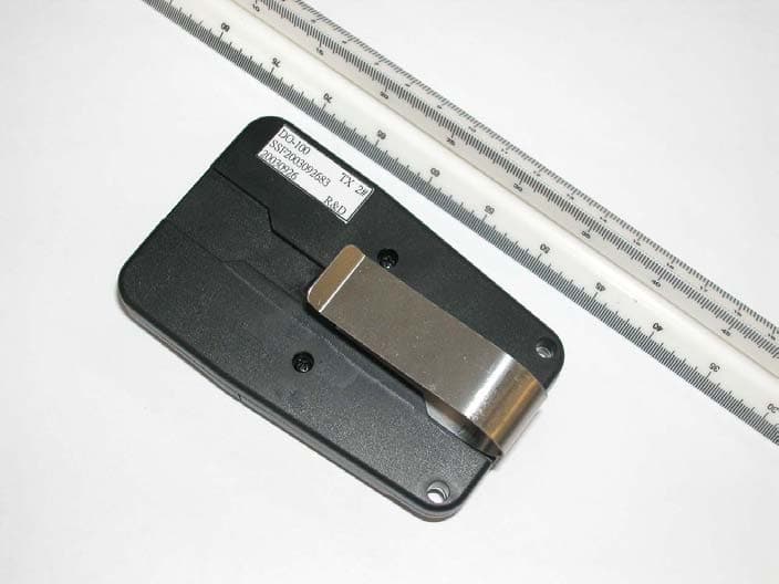
Click to zoom
Application Details
- Equipment Class
- DSC - Part 15 Security/Remote Control Transmitter
- Date of Grant
- Dec 21, 2003
- Application Purpose
- Original Equipment
- Date of Application
- Dec 21, 2003
- Equipment Note
- Gate Door Opener
- Frequency Range
- 318.00000000 - 318.00000000
- Country
- Hong Kong
Documents & Files
Document Text
Text extracted from the exhibit documents filed with the FCC. Open a document above to read the original.
Users Manual
I F YO U WI L L B E U SI N G A K E Y C H A I N MI N I T R A N SMI T T E R (Figure C), it will operate the same as the Single E ntry transmitter. B oth will work with any of our trinary coded receivers. I MP O RTA N T: T he exact same code must be set on your existing transmitter(s) and your Mini Transmitter. I f just one switch is mismatched, the controls will not function. I f you are adding the Mini Transmitter to your existing controls, verify the exact code you are currently using on your standard transmitter. Do not set your existing transmitter(s) to the factory code of the Mini Transmitter. 1. R emove the Transmitter C over R emove the screw from the back of the Mini Transmitter with a small Phillips screwdriver. L ay the transmitter down with the button facing up. U nsnap the top of the transmitter to access the coding switches. 2. Set the C oding Switches T here are nine (9) dip switches, each of which can be placed in three different positions (+,0,-). Set the switches in the Mini T ransmitter to exactly match your existing transmitter(s). DO N OT set all switches in the same position, such as all+, all -, or all zeros (Figure D). WA R N I N G : N o other adjustments should be made inside the transmitter. 3. R eassemble the Transmitter When you are sure that all the switches are set the same in all transmitters put the top back on the Mini Transmitter and tighten the Phillips screw. R emember to place the necklace chain or key ring in the eye of the transmitter case before you snap the transmitter back together. N OT E : I f the red light on the transmitter is dim or flickers when the transmitter button is pushed, the transmitter battery may be weak. R eplace when necessary with a 12 Volt battery (available at most camera stores). I N ST RU C T I O N S F O R K E Y C H A I N MI N I T R A N SMI T T E R K P amp Q@R@S@T@U@V@W@X@Y@ Figure C Figure D Your G TO ̈ A ccessory is warranted by the manufacturer against defects in materials and manufacturer workmanship for a period of one (1) year from date of purchase, provided the recommended installation procedures have been followed. G TO ̈ sells its products through authorized retail and on-line channels to ensure that consumers obtain quality pre-sale and after sale support and service. T he warranty on G TO ̈ products is N OT VAL I D if the products have been purchased from an unauthorized, on-line E -tailer (e.g., E -bay ̈ sellers who are not authorized G TO ̈ resellers), or if a product's serial number has been altered, removed, or replaced in any way. To verify that you are buying from an authorized, on-line G TO ̈ E -tailer, visit www.gtoinc.com, or call 1-800-543-G AT E . I n the case of product failure due to defective material or manufacturer workmanship within the one (1) year warranty period, the opener will be repaired or replaced (at the manufacturer's option) at no charge to the customer, if returned freight prepaid to G TO, I nc., 3121 H artsfield R oad, Tallahassee, F lorida, U SA 32303. I MPORTA N T: C all (850) 575-4144 or Fax (850) 575-8950 for a R eturn G oods A uthorization (R G A ) number before returning item(s) to the factory. Products shipped to the factory without an R G A number will not be accepted. R eplacement or repaired parts are covered by this warranty for the remainder of the one (1) year warranty period or six (6) months, whichever is greater. G TO ̈ will pay shipping costs (equal to U nited Parcel Service ground rate) for return to owner of item(s) repaired under warranty. T he manufacturer will not be responsible for any charges or damages incurred in the removal of the defective parts for repair, or the reinstallation of these parts after repair. U se of any components that are not G TO ̈ specified (e.g. battery or transformer) will void the warranty. This warranty shall be considered void if damage to the product(s) was due to improper installation or use, use of non-G TO ̈ specified or approved components or replacement parts, connection to an improper power source, or if damage was caused by lightning, wind, fire, flood, insects, or other natural agents. T his warranty gives you specific legal rights, and you may also have other rights which may vary from state to state. T his warranty is in lieu of all other warranties, either expressed or implied. A fter the one (1) year warranty period expires, G TO ̈ (or one of its authorized service centers) will perform necessary repairs for a nominal fee. C all G TO ̈ at (800) 543-1236 or (850) 575-4144 for more information. WA R R A N T Y T he two and three button transmitters are used for the remote control of two or three gate openers and/or garage door openers (Figure E). 1. R emove the Transmitter C over R emove the access cover from the front of the transmitter by sliding the cover away from the top of the transmitter. T his will expose the battery and the dip switches. T he code can now be changed using a small screwdriver. 2. Setting the C odes T here are eight (8) dip switches, each of which can be placed in three different positions (+,0,-). DO N OT set all switches in the same position, such as all +, all -, or all zeros (F igure F ). WA R N I N G : N o other adjustments should be made inside the transmitter. 3. C ommit the C ode to Memory in C ontrol B oard R emove operator control box lid. L ocate the L E A R N T R A N SMI T T E R or S5 button on the control board: A .Turn the control box power switch OF F. B .While pressing the L E A R N T R A N SMI T T E R or S5 button on the control board turn the control box power switch ON and press the T R A N SMI T T E R button. C .R elease the L E A R N T R A N SMI T T E R or S5 button after approximately 5 seconds. D.C ontinue to hold the T R A N SMI T T E R button until the gate begins to move. T he new T R A N SMI T T E R code is now stored in the control board memory. 4. U sing your transmitter T he transmitter can either be hand held or mounted on the sun visor of your vehicle. To activate your …
Text truncated - open the document above for the full version.
External Photos
Test Setup FCCID : N9KSMARTECDO100TX External Photo - front External Photo - rear
Internal Photos
Test Setup FCC ID : N9KSMARTECDO100TX Internal Photo - 1 Internal Photo - 2 Test Setup FCC ID : N9KSMARTECDO100TX Internal Photo - 3 Internal Photo - 4
Test Report
• The test results reported in this test report shall refer only to the sample actually tested and shall not refer or be deemed to refer to bulk from which such a sample may be said to have been obtained. • This report shall not be reproduced except in full without prior authorization from Intertek Testing Services Hong Kong Limited. • For Terms And Conditions of the services, it can be provided upon request. • The evaluation data of the report will be kept for 3 years from the date of issuance. Intertek Testing Services Hong Kong Ltd. 2/F., Garment Centre, 576 Castle Peak Road, Kowloon, Hong Kong. Tel: (852) 2173 8888 Fax: (852) 2371 0521 Website: www.hk.intertek-etlsemko.com Smart Technologies & Investment Ltd. Application For Certification (FCC ID: N9KSMARTECDO100TX) Transmitter 0316335 DL/ Sandy November 20, 2003 INTERTEK TESTING SERVICES FCC ID: N9KSMARTECDO100TX i LIST OF EXHIBITS INTRODUCTION EXHIBIT 1: General Description EXHIBIT 2: System Test Configuration EXHIBIT 3: Emission Results EXHIBIT 4: Equipment Photographs EXHIBIT 5: Product Labelling EXHIBIT 6: Technical Specifications EXHIBIT 7: Instruction Manual EXHIBIT 8: Miscellaneous Information INTERTEK TESTING SERVICES FCC ID: N9KSMARTECDO100TX ii MEASUREMENT/TECHNICAL REPORT Smart Technologies & Investment Ltd. - MODEL: Smartec DO-100 GTO FM135 GTO RB741 FCC ID: N9KSMARTECDO100TX November 20, 2003 This report concerns (check one:) Original Grant X Class II Change Equipment Type: Low Power Transmitter (example: computer, printer, modem, etc.) Deferred grant requested per 47 CFR 0.457(d)(1)(ii)? Yes No X If yes, defer until: date Company Name agrees to notify the Commission by: date of the intended date of announcement of the product so that the grant can be issued on that date. Transition Rules Request per 15.37? Yes No X If no, assumed Part 15, Subpart C for intentional radiator - the new 47 CFR [08-20-02 Edition] provision. Report prepared by: Derek Leung Intertek Testing Services 2/F., Garment Center, 576, Castle Peak Road, HONG KONG. Phone: 852-2173-8504 Fax: 852-2371-0521 INTERTEK TESTING SERVICES FCC ID: N9KSMARTECDO100TX iii Table of Contents 1.0 General Description............................................................................................. 2 1.1 Product Description............................................................................................. 2 1.2 Related Submittal(s) Grants................................................................................. 2 1.3 Test Methodology................................................................................................ 3 1.4 Test Facility......................................................................................................... 3 2.0 System Test Configuration .................................................................................. 5 2.1 Justification ......................................................................................................... 5 2.2 EUT Exercising Software ..................................................................................... 5 2.3 Special Accessories ............................................................................................ 5 2.4 Equipment Modification ....................................................................................... 6 2.5 Measurement Uncertainty.................................................................................... 6 2.6 Support Equipment List and Description.............................................................. 6 3.0 Emission Results ................................................................................................. 8 3.1 Field Strength Calculation.................................................................................... 9 3.2 Radiated Emission Configuration Photograph .................................................... 11 3.3 Radiated Emission Data .................................................................................... 12 4.0 Equipment Photographs .................................................................................... 15 5.0 Product Labelling............................................................................................... 17 6.0 Technical Specifications .................................................................................... 19 7.0 Instruction Manual .............................................................................................. 21 8.0 Miscellaneous Information................................................................................. 23 8.1 Measured Bandwidth......................................................................................... 24 8.2 Discussion of Pulse Desensitization ................................................................... 25 8.3 Calculation of Average Factor............................................................................ 26 8.4 Emissions Test Procedures............................................................................... 27 INTERTEK TESTING SERVICES FCC ID: N9KSMARTECDO100TX iv List of attached file Exhibit type File Description filename Test Report Test Report report.pdf Operation Description Technical Description descri.pdf Test Setup Photo Radiated Emission radiated photos.doc Test Report Bandwidth Plot bw.pdf External Photo External Photo external photos.doc Internal Photo Internal Photo internal photos.doc Block Diagram Block Diagram block.pdf Schematics Circuit Diagram circuit.pdf ID Label/Location Label Artwork and Location label.pdf User Manual User Manual manual.pdf Test Report Timing Diagram timing.pdf INTERTEK TESTING SERVICES FCC ID: N9KSMARTECDO100TX 1 EXHIBIT 1 GENERAL DESCRIPTION INTERTEK TESTING SERVICES FCC ID: N9KSMARTECDO100TX 2 1.0 General Description 1.1 Product Description The Equipment Under Test (EUT) is a Transmitter operating at 318MHz. The EUT is powered by 12V d.c. (1 x 23AE 12V Alkaline Battery). During normal use, first set…
Text truncated - open the document above for the full version.
Test Setup Photos
Test Setup FCC ID : N9KSMARTECDO100TX Radiated - front Radiated - rear
Contact Information
Applicant
Ling Li(Sales Admin. Manager)
Technical Contact
Intertek Testing Services Hong Kong Ltd.Derek Leung
[email protected]852-2173-8504
2/F., Garment Centre, · Kowloon, · Hong Kong
Non-Technical Contact
Intertek Testing Services Hong KongDerek Leung
[email protected]852-2173-8504
Test Firm
Intertek Testing Services Hong KongBilly Chow
Technical Specifications
| # | Rule Parts | Frequency Range | Power Output |
|---|---|---|---|
| 1 | 15.231 | 318 MHz - 318 MHz | - |
Other Applications from Smart Technologies & Investment Ltd
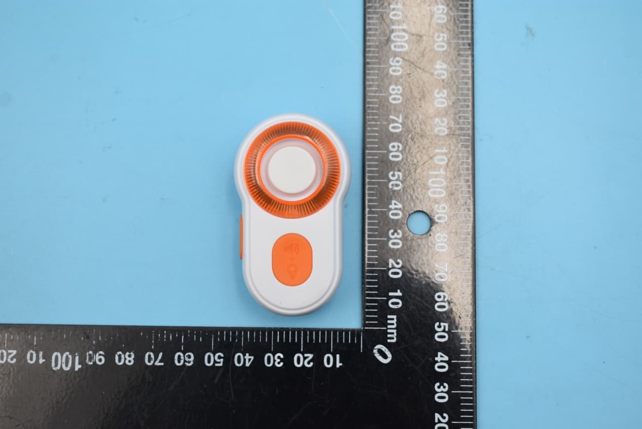
N9KSMARTMD328E
Jan 11, 2020Bluetooth Personal Alarm
Equipment Class
DTS - Digital Transmission System
N9KSMARTMA0136
Dec 10, 2015MaceAlert Smart Panel
Equipment Class
DTS - Digital Transmission System
N9KSMARMA136TX
Dec 10, 2015Keychain Remote Control
Equipment Class
DSC - Part 15 Security/Remote Control Transmitter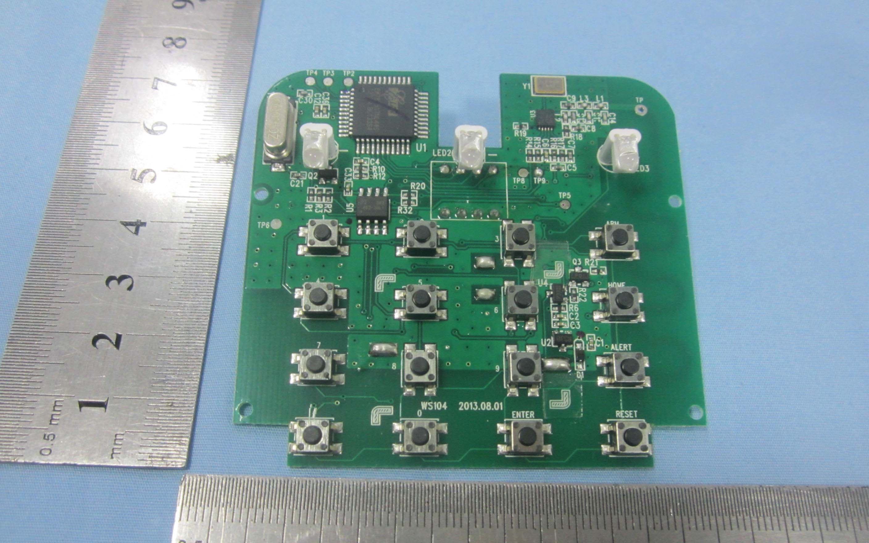
N9KSMARTWS104
Nov 14, 2013KEY PAD CONTROL
Equipment Class
DSC - Part 15 Security/Remote Control Transmitter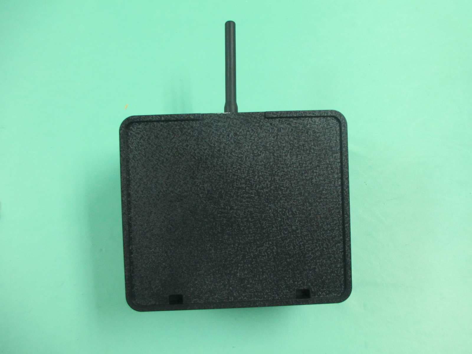
N9KGTOF3100
Jul 08, 2013GTO ACCESS WIRELESS ESTATE INTERCOM
Equipment Class
DXX - Part 15 Low Power Communication Device Transmitter