N9KSMARTECSD2706Driveway Alert
Smart Technologies & Investment Ltd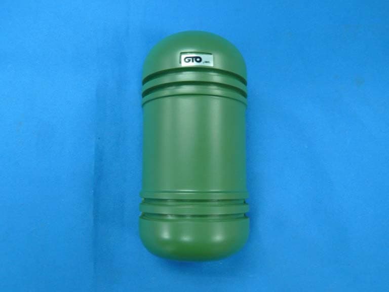
Click to zoom
Application Details
- Equipment Class
- DSC - Part 15 Security/Remote Control Transmitter
- Date of Grant
- Mar 16, 2008
- Application Purpose
- Original Equipment
- Date of Application
- Mar 16, 2008
- Equipment Note
- Driveway Alert
- Frequency Range
- 433.92000000 - 433.92000000
- Country
- Hong Kong
Documents & Files
Document Text
Text extracted from the exhibit documents filed with the FCC. Open a document above to read the original.
Users Manual
ACCESS SYSTEMS GTO Driveway Alert INSTALLATION MANUAL Kit Includes: • Transmitter • Receiver • Two Size C batteries. • GTO Driveway Alert installation manual for general installation guidance. Rev. 01/29/08 • Printed in China for GTO, Inc. Transmitter Receiver How it works: The Transmitter: The Operating Voltage for the Transmitter is 3V from two batteries (LR14C 1.5V) inside the Transmitter. There is no Power Switch for this unit. Once the batteries are installed, the unit starts to function. The Receiver: The Receiver is powered by external Power Adaptor ( AC120V 60Hz / DC 12V 100 mA). A rotary switch controls the alert buzzer’s volume on the receiver. There are three LEDs on the front Panel of cabinet, representing Power (red), Visitor Alert (green) and Low Battery (red). A “RESET” button in black on Front Panel is used to clear the alert LED after it registered passing vehicles. Thank you for purchasing the GTO Driveway Alert. Please read the directions carefully and completely before installing. For more information on GTO's full line of automatic gate openers and access controls visit our website at www.gtoaccess.com 2 Driveway Alert Above is a typical location that a transmitter would be placed in order to be effective for the application. Installation Overview • Determine the optimum location for the VEHICLE SENSOR using the information found above in the “Installation Overview”. The optimal position for the sensor / transmitter is suggested at 18 inch tall from ground surface. The receiver is also recommended to be placed at about 3 feet above the floor surface. Neither the Transmitter nor the Receiver should be placed near any metal parts. IMPORTANT: Clear an area 20 feet in all directions of metal tools, toys and automobiles, to prevent magnetic disturbance during testing and installation. System Installation Determining Transmitter and Receiver Location For Optimum Performance: • Locate the TRANSMITTER as far as possible away from power transformers, power lines, underground gas line, and telephone lines. • Locate the TRANSMITTER away from general moving traffic to prevent unwanted activation. Remember that the TRANSMITTER detects MAGNETIC DISTURBANCES caused by a vehicle’s mass and velocity. NOTE: Place the transmitter immediately next to the driveway to maximize the range. Driveway Correct placement maximizes range TRANSMITTER/ SENSOR: Next to driveway and 18 inches above surface RECEIVER: 3 feet above floor House Driveway Alert 3 Transmitter/Sensor Driveway Next To Driveway Receiver • The Transmitter is placed immediately next to the driveway, so it can maximally cover the driveway condition. When a car passes in front of the Transmitter, a string of data is transmitted to its Receiver by means of 433MHz Carrier Frequency. It is of Amplitude Shift Keying (ASK) type. After receiving the data, the Buzzer would give “Beep” twice, and the Visit Alert LED (green) would flash 3 times and remain lit up, until the RESET button is pressed. When the Low Battery LED (red) lights up, the 2x C sized batteries in the transmitter should be replaced ASAP. System Operation Receiver Operation • After the Receiver is connected to the Power through the external Power Adaptor, the Power LED on Front Panel will light up, and there will be a confirmation “Beep” tone. Transmitter Operation Low Battery LED Receiver FCC WARNING: Changes or modifications to this unit not expressly approved by the party responsible for compliance could void the user’s authority to operate the equipment. NOTE: This equipment has been tested and found to comply with the limits for a Class B digital device, pursuant to Part 15 of the FCC Rules. These limits are designed to provide reasonable protection against harmful interference in a residential installation. This equipment generates, uses and can radiate radio frequency energy and, if not installed and used in accordance with the instructions, may cause harmful interference to radio communications. However, there is no guarantee that interference will not occur in particular installations. If this equipment does cause harmful interference to radio or television reception, which can be determined by turning the equipment off and on, the user is encouraged to try to correct the interference by one or more of the following measures: • Reorient or replace the receiver antenna. • Increase the separation between the equipment and the receiver. • Connect the equipment into an outlet on a circuit different from that to which the receiver is connected. • Consult the dealer or an experienced radio/TV technician for help. GTO Limited One Year Warranty GTO, Inc., gate openers and accessories are covered under warranty by the manufacturer against defects in materials and manufacturer workmanship for a period of one (1) year from date of purchase, provided the recommended installation procedures have been followed. In the case of product failure due to defective material or manufacturer workmanship within the one (1) year warranty period, the product will be repaired or replaced (at the manufacturer’s option) at no charge to the customer, if returned freight prepaid to GTO, Inc., 3121 Hartsfield Road, Tallahassee, Florida, USA 32303. IMPORTANT: Call (800) 543-1236 for a Return Goods Authorization (RGA) number before returning accessory to factory. Products received at the factory without an RGA number will not be accepted. Replacement or repaired parts are covered by this warranty for the remainder of the one (1) year warranty period or six (6) months, whichever is greater. GTO, Inc. will pay the shipping charges (equal to United Parcel Service GROUND rate) for return to the owner of items repaired under warranty. The manufacturer will not be responsible for any charges or damages incurred in the removal of the defective parts for repair, or for the reinstallation of those parts after repair. This warranty shall be considered void if damage to the product(s) was due to improper in…
Text truncated - open the document above for the full version.
External Photos
Page 6 Smart Technologies & Investment Ltd.Driveway Alert FCC ID:N9KSMARTECSD2706 Photographs Figure 1 General Appearance of the EUT Figure 2 General Appearance of the EUT Label Location
ID Label/Location Info
Operation is subject to the following two conditions: (1)This device may not cause harmful interference,and (2)This device must accept any interference received, Including interference that may cause undesired operation. This device complies with PART 15 of the FCC rules. FCC ID:N9KSMARTECSD2706 45mm 20mm Page 6 Smart Technologies & Investment Ltd.Driveway Alert FCC ID:N9KSMARTECSD2706 Photographs Figure 1 General Appearance of the EUT Figure 2 General Appearance of the EUT Label Location
Internal Photos
Page 7 Smart Technologies & Investment Ltd.Driveway Alert FCC ID:N9KSMARTECSD2706 Figure 3 Inside of the EUT Figure 4 Inside of the EUT Page 8 Smart Technologies & Investment Ltd.Driveway Alert FCC ID:N9KSMARTECSD2706 Figure 5 Inside of the EUT Figure 6 Inside of the EUT Page 9 Smart Technologies & Investment Ltd.Driveway Alert FCC ID:N9KSMARTECSD2706 Figure 7 Inside of the EUT
Test Report
FCC ID:N9KSMARTECSD2706 Audix Technology (Shenzhen) Co., Ltd. Report No. ACS-F08132 APPLICATION FOR CERTIFICATION On Behalf of Smart Technologies & Investment Ltd. Driveway Alert Model No. Brand Name SD2706 Smartec R4450 GTO PRO FM131 MIGHTY MULE Prepared for : Smart Technologies & Investment Ltd. Unit C&D, 18/F Spectrum Tower, 53 Hung To Road, Kwun Tong, Kowloon, Hong Kong. Prepared By : Audix Technology (Shenzhen) Co., Ltd. No. 6, Ke Feng Rd., 52 Block, Shenzhen Science & Industrial Park, Nantou, Shenzhen, Guangdong, China Tel: (0755) 26639496 Report Number : ACS-F08132 Date of Test : Feb.21~22, 2008 Date of Report : Mar.11, 2008 FCC ID:N9KSMARTECSD2706 Audix Technology (Shenzhen) Co., Ltd. Report No. ACS-F08132 TABLE OF CONTENTS Description Page Test Report Declaration 1. SUMMARY OF STANDARDS AND RESULTS .................................................................. 1-1 1.1. Description of Standards and Results.............................................................................................1-1 2. GENERAL INFORMATION .................................................................................................. 2-1 2.1. Description of Device (EUT) .........................................................................................................2-1 2.2. Test Facility....................................................................................................................................2-2 2.3. Measurement Uncertainty ..............................................................................................................2-2 3. POWER LINE CONDUCTED EMISSION TEST................................................................ 3-1 4. RADIATED EMISSION TEST ............................................................................................... 4-1 4.1. Test Equipment ..............................................................................................................................4-1 4.2. Block Diagram of Test Setup .........................................................................................................4-1 4.3. Radiated Emission Limit (Standard: FCC Part 15) Radiated Emission Limit (15.231 section b) .4-2 4.4. EUT Configuration on Test............................................................................................................4-2 4.5. Operating Condition of EUT..........................................................................................................4-3 4.6. Test Procedure................................................................................................................................4-3 4.7. Radiated Emission Test Results .....................................................................................................4-3 5. STOP TRANSMITTING TIME TEST .................................................................................. 5-1 5.1. Test Equipment ..............................................................................................................................5-1 5.2. Test Information .............................................................................................................................5-1 5.3. Test Results ....................................................................................................................................5-1 6. 20 DB BANDWITH TEST ....................................................................................................... 6-1 6.1. Test Equipment ..............................................................................................................................6-1 6.2. Test Information .............................................................................................................................6-1 6.3. Test Results ....................................................................................................................................6-1 7. MODULATION INFO ............................................................................................................. 7-1 8. DEVIATION TO TEST SPECIFICATIONS ........................................................................ 8-1 9. PHOTOGRAPH........................................................................................................................ 9-1 9.1. Photos of Radiated Emission Test (In Anechoic Chamber) ...........................................................9-1 FCC ID:N9KSMARTECSD2706 Audix Technology (Shenzhen) Co., Ltd. Report No. ACS-F08132 TEST REPORT CERTIFICATION Applicant : Smart Technologies & Investment Ltd. Manufacturer : Smart Electronic Industrial (DONGGUAN) Co., Ltd. EUT Description : Driveway Alert (A) Model No.& Brand Name : Model No. Brand Name SD2706 Smartec R4450 GTO PRO FM131 MIGHTY MULE (B) Serial No. : N/A (C) Power Supply : DC 3V Test Procedure Used: FCC Rules and Regulations Part 15 Subpart C 2007 The device described above is tested by Audix Technology (Shenzhen) Co., Ltd. to determine the maximum emission levels emanating from the device. The maximum emission levels are compared to the FCC Part 15 Subpart C limits for radiated and conducted emissions. The test results are contained in this test report and Audix Technology (Shenzhen) Co., Ltd. is assumed full responsibility for the accuracy and completeness of tests. Also, this report shows that EUT is technically compliant with FCC requirements. This report applies to above tested sample only. This report shall not be reproduced in part without written approval of Audix Technology (Shenzhen) Co., Ltd. Date of Test : Feb.21~22, 2008 Prepared by : YoYo Wang / Assistant Reviewer : Iceman Hu / Supervisor Approved & Authorized Signer : Ken Lu / Deputy Manager FCC ID:N9KSMARTECSD2706 Page Audix Technology (Shenzhen) Co., Ltd. Report No. ACS-F08132 1-1 1. SUMMARY OF STANDARDS AND RESULTS 1.1. Description of Standards and Results The EUT have been tested according to the applicable standards as referenced …
Text truncated - open the document above for the full version.
Test Setup Photos
FCC ID:N9KSMARTECSD2706 Page 9-1 Audix Technology (Shenzhen) Co., Ltd. Report No. ACS-F08132 9. PHOTOGRAPH 9.1. Photos of Radiated Emission Test (In Anechoic Chamber) Frequency Range: 30-1000MHz X Position Y Position FCC ID:N9KSMARTECSD2706 Page 9-2 Audix Technology (Shenzhen) Co., Ltd. Report No. ACS-F08132 Z Position Frequency Range: Above 1000MHz X Position FCC ID:N9KSMARTECSD2706 Page 9-3 Audix Technology (Shenzhen) Co., Ltd. Report No. ACS-F08132 Y Position Z Position
Contact Information
Applicant
Ling Li(Sales Admin. Manager)
Technical Contact
Audix TechnologyKen Lu
[email protected]86-755-2663-9497
52 Block Shenzhen Science Industry · Shenzhen · China
Test Firm
Audix Technology (Shenzhen) Co., Ltd.Smart Tsai
Technical Specifications
| # | Rule Parts | Frequency Range | Power Output |
|---|---|---|---|
| 1 | 15.231 | 433.92 MHz - 433.92 MHz | - |
Other Applications from Smart Technologies & Investment Ltd
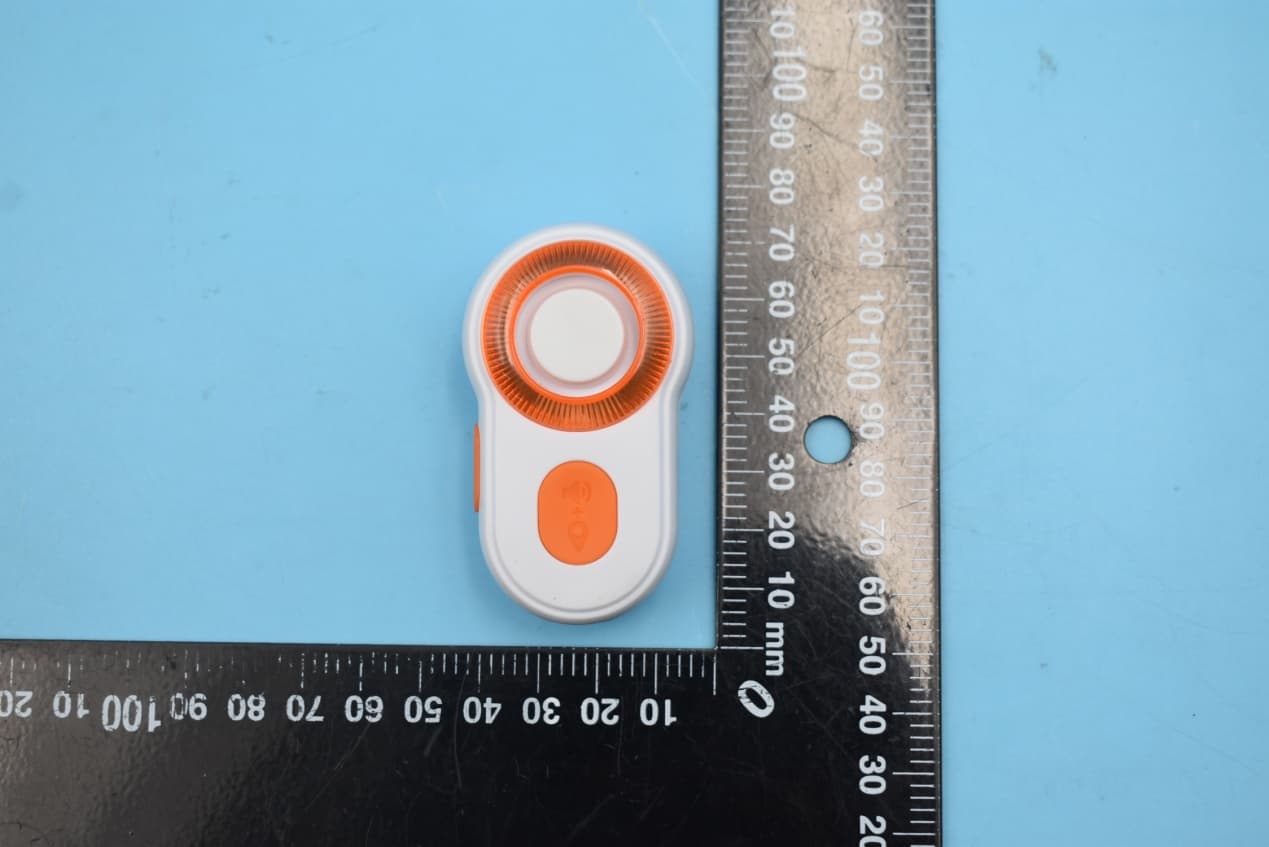
N9KSMARTMD328E
Jan 11, 2020Bluetooth Personal Alarm
Equipment Class
DTS - Digital Transmission System
N9KSMARTMA0136
Dec 10, 2015MaceAlert Smart Panel
Equipment Class
DTS - Digital Transmission System
N9KSMARMA136TX
Dec 10, 2015Keychain Remote Control
Equipment Class
DSC - Part 15 Security/Remote Control Transmitter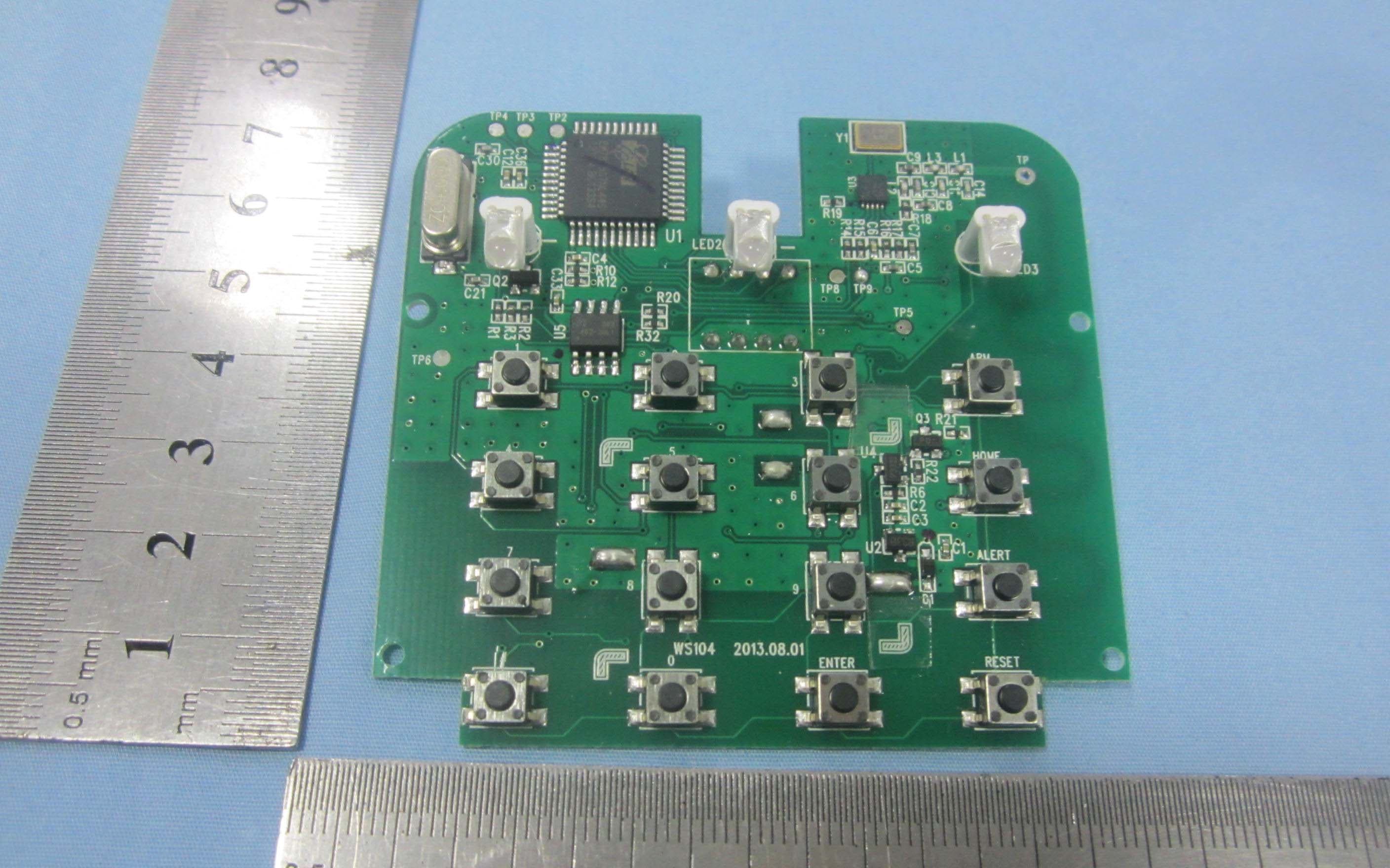
N9KSMARTWS104
Nov 14, 2013KEY PAD CONTROL
Equipment Class
DSC - Part 15 Security/Remote Control Transmitter
N9KGTOF3100
Jul 08, 2013GTO ACCESS WIRELESS ESTATE INTERCOM
Equipment Class
DXX - Part 15 Low Power Communication Device Transmitter