N9KSMARTECSD2707Wireless Wand KIT
Smart Technologies & Investment Ltd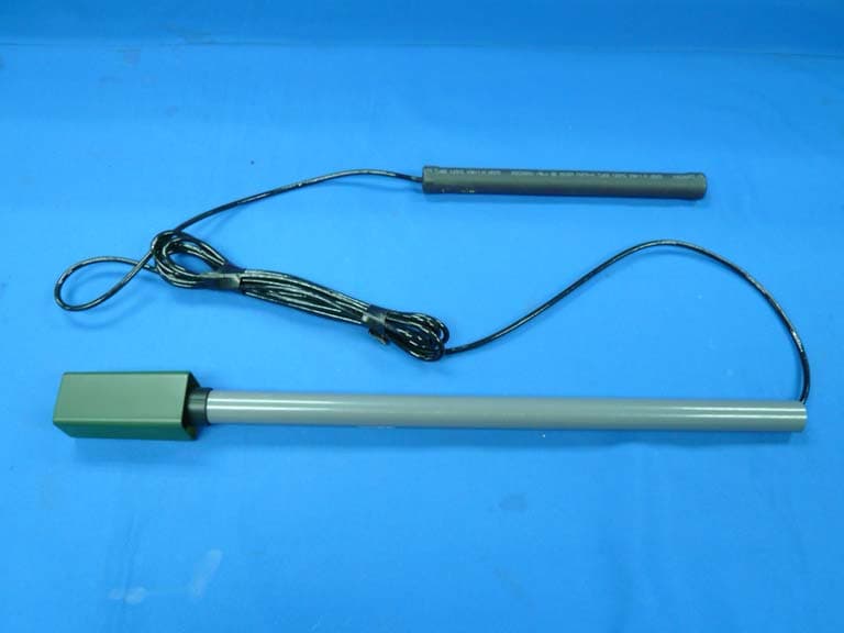
Click to zoom
Application Details
- Equipment Class
- DSC - Part 15 Security/Remote Control Transmitter
- Date of Grant
- Mar 16, 2008
- Application Purpose
- Original Equipment
- Date of Application
- Mar 16, 2008
- Equipment Note
- Wireless Wand KIT
- Frequency Range
- 318.00000000 - 318.00000000
- Country
- Hong Kong
Documents & Files
Document Text
Text extracted from the exhibit documents filed with the FCC. Open a document above to read the original.
Users Manual
GTO Wireless Exit Sensor INSTALLATION MANUAL Kit Includes: • Wireless vehicle sensor with direct burial coil assembly and a plug-in electronics/transmitter module designed for mounting up to 15 feet away from the pavement edge. • RB709U-NB two channel receiver with instructions. • Two size AA batteries. • GTO Wireless Exit Sensor instruction manual for general installation guidance. Rev. 01/21/08 • Printed in China for GTO, Inc. Signal Cable Vehicle Sensor Module Cover Electronics/Transmitter Module Programmable Dip Switches How it works: The GTO wireless exit sensor consists of a vehicle sensor, transmitter, and programmable dip switches. The maximum range between transmitter and receiver is 80- 100 ft. The transmitter module transmits a special GTO transmitter code with additional information to tell the receiver that this device should be treated as a “free exit” device. The latest GTO gate operators with blue control boards (GTO “GEN3”) are able to decode this format and recognize the device as a free exit or open only command without the use of the RB709U-NB receiver. This will simplify installations so only the original receiver will be required. The RB709U-NB receiver will be required unless you have the GEN 3 (blue board). The RB-709U-NB has two channels that can be programmed to operate a remote transmitter or keypad and wireless wand. For instance, Channel 1 could be wired to the Cycle and COM accessory terminals and could be programmed to operate a transmitter and keypad. Channel 2 could be wired to the Exit and COM accessory terminals and could be used to operate the wireless exit sensor. Depending on the frequency of use (vehicle traffic) the two AA batteries will last about 1 to 3 years. Thank you for purchasing the GTO Wireless Exit Sensor. Please read the directions carefully and completely before installing. For more information on GTO's full line of automatic gate openers and access controls visit our website at www.gtoaccess.com GTO WIRELESS EXIT WAND TRANSMITTER CODE TRANSMIT ACTIVE MINMAX SENSITIVITY GTO WIRELESS EXIT WAND TRANSMITTER CODE TRANSMIT ACTIVE MINMAX SENSITIVITY 2 Wireless Exit Sensor Above is a typical location where installing a conventional “wired” exit sensor would require cutting and trenching across more than 50 feet of asphalt driveway. Gate Opener Receiver Driveway Transmitter 100’ Max Wireless RANGE: 12 ft. radius (max) SENSOR: 2 feet from driveway (max) and 12” deep Open Gate Outside Sensor Range 25 ft. from gate (min) Sensor and Module Placement Overview • Determine the optimum location for the VEHICLE SENSOR using the information found above in “Sensor and Transmitter Placement Overview”. Then dig a hole approximately 10 - 12 inches deep and 24 inches long within 2 feet and parallel to the edge of the driveway. Next, dig a trench no more than 15 ft from this hole to the location where you will install the transmitter module. Keep the VEHICLE SENSOR and the cable uncovered at this time. IMPORTANT: Clear an area 20 feet in all directions of metal tools, toys and automobiles, to prevent magnetic disturbance during testing and installation. Sensor Placement Determining Sensor Location For Optimum Performance: • Locate the SENSOR as far as possible away from power transformers, power lines, underground gas line, and telephone lines. • Locate the SENSOR away from general moving traffic to prevent unwanted activation. Remember that the SENSOR detects MAGNETIC DISTURBANCES caused by a vehicle’s mass and velocity. • Range distance is approximate and will vary due to outside interference, type of soil, vehicle mass, speed, etc. • It is recommended that you run the Signal Cable inside PVC conduit to prevent accidental damage. • Do not run Signal Cable in conduit with other wires such as AC power or other control wires. • The SIGNAL CABLE CANNOT BE SPLICED. If you need more wire, contact the GTO Sales Department at 1-800-543-GATE (4283). NOTE: Place the transmitter on the same side of the driveway in the line of sight of the receiver to maximize the range. Wireless Exit Sensor 3 Receiver Transmitter Module Driveway 10 -12 inch deep pit 15 ft maximum Vehicle Sensor 100 ft Maximum Install the Vehicle Sensor DO NOT fill the hole until final testing is complete. • Dig a small pit about 10 - 12 inches deep close to the edge of your driveway. The hole should allow you to lay the Vehicle Sensor flat in the bottom with the length of the Vehicle Sensor parallel to the direction of the driveway. • After laying the vehicle sensor in the hole adjacent to the driveway. Run the signal cable to the transmitter module in the narrow trench. Do not fill the hole or trench until satisfactory operation is verified. Vehicle Sensor 10-12 inch deep pit Placed 2 ft maximum from edge of driveway Vehicle Sensor should lay parallel to driveway D R I V E W A Y Transmitter Module Placement Determining Transmitter Module Location • Choose a location for the transmitter module that is far enough from the driveway edge that vehicles are unlikely to hit it. Fifteen feet of wire is included to allow the transmitter to be 12 to 15 feet from the driveway. To test the chosen location to be sure it is free from obstructions or other interference, you can use your remote control transmitter at the same height as the transmitter module to activate the gate. 4 Wireless Exit Sensor 6 inches deep Sensor NOTE: DO NOT place in the direct path of a sprinkler. The module is water resistant but not waterproof. • Dig a narrow trench or slit from the Vehicle Sensor to the transmitter location using a flat spade or other tool. The wire from the wand to the transmitter should be at least six inches deep to avoid possible damage from edgers, or lawn aerators. GTO WIRELESS EXIT WAND TRANSMITTER CODE MED TRANSMIT ACTIVE MINMAX SENSITIVITY • Feed the Signal Cable through the PVC pipe and plug into the connector at the bottom of the Electronics/Transmitter module. Connecting the Electronics/Transmitter Module I…
Text truncated - open the document above for the full version.
External Photos
Page 6 Smart Technologies & Investment Ltd.Wireless Wand KIT FCC ID:N9KSMARTECSD2707 Photographs Figure 1 General Appearance Figure 2 Inside of the EUT Label Location
ID Label/Location Info
Operation is subject to the following two conditions: (1)This device may not cause harmful interference,and (2)This device must accept any interference received, Including interference that may cause undesired operation. This device complies with PART 15 of the FCC rules. FCC ID:N9KSMARTECSD2707 45mm 20mm Page 6 Smart Technologies & Investment Ltd.Wireless Wand KIT FCC ID:N9KSMARTECSD2707 Photographs Figure 1 General Appearance Figure 2 Inside of the EUT Label Location
Internal Photos
Page 7 Smart Technologies & Investment Ltd.Wireless Wand KIT FCC ID:N9KSMARTECSD2707 Figure 3 Inside of the EUT Figure 4 Inside of the EUT Page 8 Smart Technologies & Investment Ltd.Wireless Wand KIT FCC ID:N9KSMARTECSD2707 Figure 5 Inside of the EUT Figure 6 Inside of the EUT Page 9 Smart Technologies & Investment Ltd.Wireless Wand KIT FCC ID:N9KSMARTECSD2707 Figure 7 Inside of the EUT
Test Report
FCC ID:N9KSMARTECSD2707 Audix Technology (Shenzhen) Co., Ltd. Report No. ACS-F08133 APPLICATION FOR CERTIFICATION On Behalf of Smart Technologies & Investment Ltd. Wireless Wand KIT Model No. Brand Name SD2707 Smartec R4500 GTO PRO FM130 MIGHTY MULE Prepared for : Smart Technologies & Investment Ltd. Unit C&D, 18/F Spectrum Tower, 53 Hung To Road, Kwun Tong, Kowloon, Hong Kong. Prepared By : Audix Technology (Shenzhen) Co., Ltd. No. 6, Ke Feng Rd., 52 Block, Shenzhen Science & Industrial Park, Nantou, Shenzhen, Guangdong, China Tel: (0755) 26639496 Report Number : ACS-F08133 Date of Test : Feb.21~22, 2008 Date of Report : Mar.11, 2008 FCC ID:N9KSMARTECSD2707 Audix Technology (Shenzhen) Co., Ltd. Report No. ACS-F08133 TABLE OF CONTENTS Description Page Test Report Declaration 1. SUMMARY OF STANDARDS AND RESULTS .................................................................. 1-1 1.1. Description of Standards and Results.............................................................................................1-1 2. GENERAL INFORMATION .................................................................................................. 2-1 2.1. Description of Device (EUT) .........................................................................................................2-1 2.2. Test Facility....................................................................................................................................2-2 2.3. Measurement Uncertainty ..............................................................................................................2-2 3. POWER LINE CONDUCTED EMISSION TEST................................................................ 3-1 4. RADIATED EMISSION TEST ............................................................................................... 4-1 4.1. Test Equipment ..............................................................................................................................4-1 4.2. Block Diagram of Test Setup .........................................................................................................4-1 4.3. Radiated Emission Limit (15.231 section b) ..................................................................................4-2 4.4. EUT Configuration on Test............................................................................................................4-2 4.5. Operating Condition of EUT..........................................................................................................4-3 4.6. Test Procedure................................................................................................................................4-3 4.7. Radiated Emission Test Results .....................................................................................................4-3 5. STOP TRANSMITTING TIME TEST .................................................................................. 5-1 5.1. Test Equipment ..............................................................................................................................5-1 5.2. Test Information .............................................................................................................................5-1 5.3. Test Results ....................................................................................................................................5-1 6. 20 DB BANDWITH TEST ....................................................................................................... 6-1 6.1. Test Equipment ..............................................................................................................................6-1 6.2. Test Information .............................................................................................................................6-1 6.3. Test Results ....................................................................................................................................6-1 7. MODULATION INFO ............................................................................................................. 7-1 8. DEVIATION TO TEST SPECIFICATIONS ........................................................................ 8-1 9. PHOTOGRAPH........................................................................................................................ 9-1 9.1. Photos of Radiated Emission Test (In Anechoic Chamber) ...........................................................9-1 FCC ID:N9KSMARTECSD2707 Audix Technology (Shenzhen) Co., Ltd. Report No. ACS-F08133 TEST REPORT CERTIFICATION Applicant : Smart Technologies & Investment Ltd. Manufacturer : Smart Electronic Industrial (DONGGUAN) Co., Ltd. EUT Description : Wireless Wand KIT (A) Model No.& Brand Name : Model No. Brand Name SD2707 Smartec R4500 GTO PRO FM130 MIGHTY MULE (B) Serial No. : N/A (C) Power Supply : DC 3V Test Procedure Used: FCC Rules and Regulations Part 15 Subpart C 2007 The device described above is tested by Audix Technology (Shenzhen) Co., Ltd. to determine the maximum emission levels emanating from the device. The maximum emission levels are compared to the FCC Part 15 Subpart C limits for radiated and conducted emissions. The test results are contained in this test report and Audix Technology (Shenzhen) Co., Ltd. is assumed full responsibility for the accuracy and completeness of tests. Also, this report shows that EUT is technically compliant with FCC requirements. This report applies to above tested sample only. This report shall not be reproduced in part without written approval of Audix Technology (Shenzhen) Co., Ltd. Date of Test : Feb.21~22, 2008 Prepared by : YoYo Wang / Assistant Reviewer : Iceman Hu / Supervisor Approved & Authorized Signer : Ken Lu / Deputy Manager FCC ID:N9KSMARTECSD2707 Page Audix Technology (Shenzhen) Co., Ltd. Report No. ACS-F08133 1-1 1. SUMMARY OF STANDARDS AND RESULTS 1.1. Description of Standards and Results The EUT have been tested according to …
Text truncated - open the document above for the full version.
Test Setup Photos
FCC ID:N9KSMARTECSD2707 Page 9-1 Audix Technology (Shenzhen) Co., Ltd. Report No. ACS-F08133 9. PHOTOGRAPH 9.1. Photos of Radiated Emission Test (In Anechoic Chamber) Frequency Range: 30-1000MHz FCC ID:N9KSMARTECSD2707 Page 9-2 Audix Technology (Shenzhen) Co., Ltd. Report No. ACS-F08133 Frequency Range: Above 1000MHz
Contact Information
Applicant
Ling Li(Sales Admin. Manager)
Technical Contact
Audix TechnologyKen Lu
[email protected]86-755-2663-9497
52 Block Shenzhen Science Industry · Shenzhen · China
Test Firm
Audix Technology (Shenzhen) Co.Smart Tsai
Technical Specifications
| # | Rule Parts | Frequency Range | Power Output |
|---|---|---|---|
| 1 | 15.231 | 318 MHz - 318 MHz | - |
Other Applications from Smart Technologies & Investment Ltd
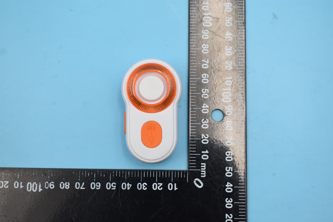
N9KSMARTMD328E
Jan 11, 2020Bluetooth Personal Alarm
Equipment Class
DTS - Digital Transmission System
N9KSMARTMA0136
Dec 10, 2015MaceAlert Smart Panel
Equipment Class
DTS - Digital Transmission System
N9KSMARMA136TX
Dec 10, 2015Keychain Remote Control
Equipment Class
DSC - Part 15 Security/Remote Control Transmitter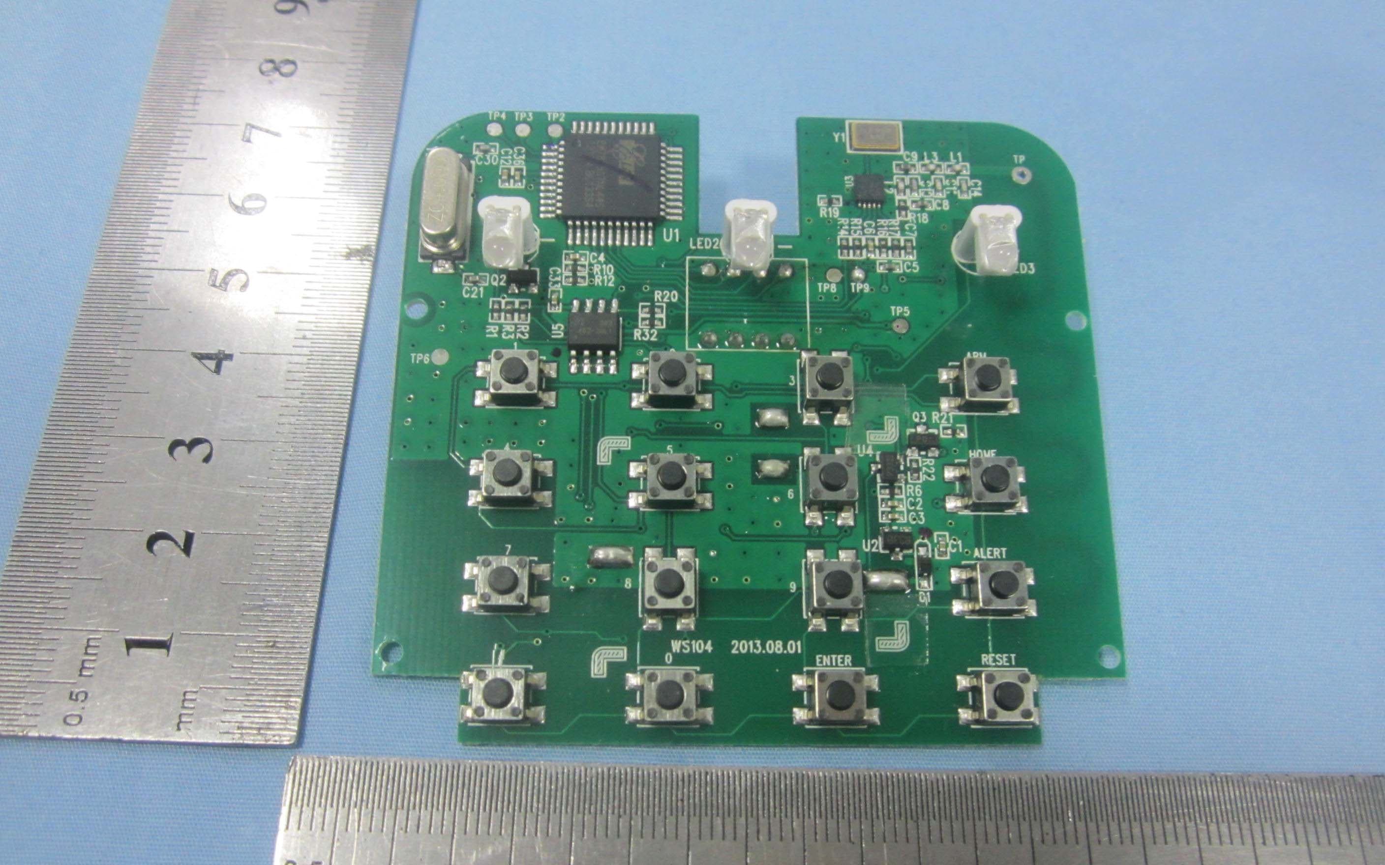
N9KSMARTWS104
Nov 14, 2013KEY PAD CONTROL
Equipment Class
DSC - Part 15 Security/Remote Control Transmitter
N9KGTOF3100
Jul 08, 2013GTO ACCESS WIRELESS ESTATE INTERCOM
Equipment Class
DXX - Part 15 Low Power Communication Device Transmitter