N9KSMARTWS210Wireless GSM dialer (Smart Control)
Smart Technologies & Investment Ltd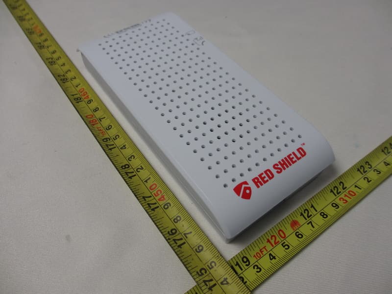
Click to zoom
Application Details
- Equipment Class
- DSC - Part 15 Security/Remote Control Transmitter
- Date of Grant
- Apr 24, 2013
- Application Purpose
- Original Equipment
- Date of Application
- Apr 24, 2013
- Equipment Note
- Wireless GSM dialer (Smart Control)
- Frequency Range
- 433.92000000 - 433.92000000
- Country
- Hong Kong
Documents & Files
Document Text
Text extracted from the exhibit documents filed with the FCC. Open a document above to read the original.
Users Manual
RED SHIELD GSM SMART CONTROL – INSTALLATION AND OPERATING INSTRUCTIONS For use with RedShield Wire-free Home Protection System Type of product: GSM Smart Control Keep this manual safe for reference and future maintenance 1. Introduction The GSM Smart Control works just like a security system keypad allowing you to access and operate your system remotely from anywhere in the world when using your Smartphone or other compatible wireless handheld devices. It's never been easier to stay in the know and stay in control. • Manage up to three premises • Alert up to 8 specific individuals using GSM network to manage the system • Listen to immediate vicinity using built in microphone • Activate, deactivate or home security system from afar • Applicable for universal 850/900/1800/1900Mhz GSM frequency 2. Choosing a Location To ensure that installation proceeds smoothly please select a suitable location. This location would ideally be close to a mains power outlet that is accessible to the user and yet not accessible to unauthorized personnel. • Fasten the device on a smooth, dry and secure foundation. Ensure that a clear GSM signal reception is present at the point of installation prior to assembly. • Avoid locations near extreme temperature sources (radiators, ovens, stoves) and large metal objects that could interfere with radio signals. 3. Installation The easiest way to get to know the system and get it up and running quickly is to have all the devices and accessories laid out before mounting them. You will need following devices to complete the set up: 1 x GSM Smart Control 1 x AC Adaptor 2 x series of screws (WS210B GSM Smart Control) Smart Panel does not come with this kit. You may contact the local distributor to purchase the full security kit) 3.1 First time installation: a. Remove the front covers of the GSM Smart Control b. Push the SIM card holder backwards as illustrated and then unfold the slot forwards. c. Insert the SIM card. Push the SIM card holder back again upwards. d. Replace and secure both covers. e. Insert batteries ensuring that they are correctly oriented and connect the AC adaptor. f. The Battery LED & Signal LED lights will light up. g. After a while they will both go out indicating that the GSM Smart Control has connected with the GSM network. The signal LED light will light up every 10 seconds to indicate the GSM Smart Control is linked to the GSM network. h. Enroll GSM Smart Control with a Smart Panel. Please refer to section 3.2 for enrolling the GSM Smart Control into a Smart Panel. i. Replace and secure cover for the battery compartment. j. Mount at intended location. 3.2 Enrolling GSM Smart Control with the Smart Panel In order to use the GSM Smart Control with the Smart Panel you will need to enroll the components. This will allow the Smart Panel to recognize and interact with the GSM Smart Control. The enrolling procedure must be completed in order for the GSM Smart Control to work properly. If the procedure is not completed then the GSM Smart Control will not respond to system input. IMPORTANT: In most cases the factory settings of the House security Code will NOT need to be changed. However if the Smart Panel and sensors activate intermittently or are unresponsive this may be due to interference with other radio frequency systems. You may wish to change the house codes ensuring that they are identically arranged in both the Smart panel and Smart Control. There are 4 jumpers/dip-switches on each device. They can be found when you remove the battery compartment cover. When the jumpers are present the circuit is ‘ON’. If absent the circuit is ‘OFF’. Ensure that these settings are identical if you need to make modifications to the panel, sensors and any remote control device. a. Enter the 4 digit pin on the Smart Panel and press the SETTING button and ‘2’ (Enrollment mode). b. Simultaneously hold down the RECORD and RESET button on the back of the GSM Smart Control for two seconds c. Several beeps from the Smart Panel will indicate that the enrollment is successful d. Press ENTER on the Smart Panel to exit the enrollment mode 3.3. Voice messages The user is able to pre-record a voice message up to 20 seconds long. The device has an integrated microphone and loudspeaker for recording and playing voice messages. Messages should be recorded so that they reflect the circumstances and provides key details. IMPORTANT: We recommend adding a note at the end of the message to remind the owner of the system to disarm the system. Otherwise, the next programmed telephone number is dialed until the dialing cycle is finished. After the last number has been dialed the Smart Control will then proceed to call the first recipient and proceed as before. The GSM Smart Control houses a sensitive microphone. This allows the user to record a short message intended for specific individuals or the emergency services. To record a message: • Hold (RECORD/PLAY) left button on the rear until BATTERY LED is continuously lit • Release (RECORD/PLAY) button • Speak into the microphone for up to 20 seconds • Press the (RECORD/PLAY) button to cut the recording if less than 20 seconds • Press the same (RECORD/PLAY) button for playback 4. Factory settings reset In order to ensure that all existing settings are deleted, a factory settings reset is recommended after a new installation. Press and hold the “RESET” button for 5 seconds. It will restore the factory default settings. 5.Setting up your Smart Control using Smart Phone Application (App) Use of the Smart Phone allows the user a convenient and readily accessible means to remotely interact with their Red Shield Security system across long distances. Search for ‘RedShield’ to find the app on your Apple® App store or Android® Google Play to download the app to your iPhone, or other applicable device. After installation of the application (App.) you will need to set it up as follows: a.) On the first time after installation determine your personali…
Text truncated - open the document above for the full version.
External Photos
Neutron Engineering Inc. Project No.: 1301C260 Page 2 of 11 Neutron Engineering Inc. Project No.: 1301C260 Page 3 of 11
Internal Photos
Neutron Engineering Inc. Project No.: 1301C260 Page 4 of 11 Neutron Engineering Inc. Project No.: 1301C260 Page 5 of 11 Neutron Engineering Inc. Project No.: 1301C260 Page 6 of 11 Neutron Engineering Inc. Project No.: 1301C260 Page 7 of 11 Neutron Engineering Inc. Project No.: 1301C260 Page 8 of 11 Neutron Engineering Inc. Project No.: 1301C260 Page 9 of 11 Neutron Engineering Inc. Project No.: 1301C260 Page 10 of 11 Neutron Engineering Inc. Project No.: 1301C260 Page 11 of 11
Test Report
Neutron Engineering Inc. Report No.: NEI-FCCP-1-1301C260 Page 1 of 38 FCC Radio Test Report FCC ID: N9KSMARTWS210 This report concerns (check one) : Original Grant Copy Report Issued Date : Feb. 26, 2013 Project No. : 1301C260 Equipment : Wireless GSM dialer (Smart Control) Model Name : WS210 Applicant : Smart Technologies & Investment Ltd. Address : Units C & D, 18/F Spectrum Tower, No. 53 Hung To Road, Kwun Tong, Kowloon, Hong Kong Tested by: Neutron Engineering Inc. EMC Laboratory Date of Receipt: Jan. 24, 2013 Date of Test: Jan. 24, 2013 ~ Feb. 25, 2013 Testing Engineer : (David Mao) Technical Manager : (Leo Hung) Authorized Signatory : (Steven Lu) Neutron Engineering Inc. No.3,Jinshagang 1st Road, ShiXia, Dalang Town, Dong Guan, China. TEL : (0769) 8318-3000 FAX : (0769) 8319-6000 Neutron Engineering Inc. Report No.: NEI-FCCP-1-1301C260 Page 2 of 38 Declaration Neutron represents to the client that testing is done in accordance with standard procedures as applicable and that test instruments used has been calibrated with the standards traceable to National Measurement Laboratory (NML) of R.O.C., or National Institute of Standards and Technology (NIST) of U.S.A. Neutron's reports apply only to the specific samples tested under conditions. It is manufacture’s responsibility to ensure that additional production units of this model are manufactured with the identical electrical and mechanical components. Neutron shall have no liability for any declarations, inferences o r generalizations drawn by the client or others from Neutron issued reports. Neutron’s reports must not be used by the client to claim product endorsement by the authorities or any agency of the Government. This report is the confidential property of the client. As a mutual protection to the clients, the public and Neutron-self, extracts from the test report shall not be reproduced except in full with Neutron’s authorized written approval. Neutron’s laboratory quality assurance procedures are in compliance with the ISO Guide 17025 requirements, and accredited by the conformity assessment authorities listed in this test report. Limitation For the use of the authority's logo is limited unless the Test Standard(s)/Scope(s)/Item(s) mentioned in this test report is (are) included in the conformity assessment authorities acceptance respective. Neutron Engineering Inc. Report No.: NEI-FCCP-1-1301C260 Page 3 of 38 Table of Contents Page 1 . CERTIFICATION 5 2 . SUMMARY OF TEST RESULTS 6 2.1 TEST FACILITY 7 2.2 MEASUREMENT UNCERTAINTY 7 3 . GENERAL INFORMATION 8 3.1 GENERAL DESCRIPTION OF EUT 8 3.2 DESCRIPTION OF TEST MODES 9 3.3 BLOCK DIGRAM SHOWING THE CONFIGURATION OF SYSTEM TESTED 10 3.4 DESCRIPTION OF SUPPORT UNITS 11 4 . EMC EMISSION TEST 12 4.1 CONDUCTED EMISSION MEASUREMENT 12 4.1.1 POWER LINE CONDUCTED EMISSION LIMITS 12 4.1.2 MEASUREMENT INSTRUMENTS LIST 12 4.1.3 TEST PROCEDURE 13 4.1.4 DEVIATION FROM TEST STANDARD 13 4.1.5 TEST SETUP 13 4.1.6 EUT OPERATING CONDITIONS 13 4.1.7 TEST RESULTS 14 4.2 RADIATED EMISSION MEASUREMENT 17 4.2.1. FIELD STRENGTH OF FUNDAMENTAL EMISSIONS MEASUREMENT LIMIT 17 4.2.2. MEASURING INSTRUMENTS AND SETTING (FIELD STRENGTH OF FUNDAMENTAL 17 EMISSIONS) 17 4.2.3 RADIATED EMISSIONS MEASUREMENT 18 4.2.4. DWELL TIME OF PERIODIC OPERATION MEASUREMENT 19 4.2.5. MEASUREMENT INSTRUMENTS LIST 20 4.2.6. TEST PROCEDURE 20 4.2.7. DEVIATION FROM TEST STANDARD 20 4.2.8. TEST SETUP 21 4.2.9. EUT OPERATING CONDITIONS 22 4.3.0TEST RESULTS ((BELOW 30MHz)) 23 4.3.1 TEST RESULTS (BETWEEN 30 – 1000 MHz) 24 4.3.2 TEST RESULTS (ABOVE 1000 MHz) 27 5. 20dB SPECTRUM BANDWIDTH MEASUREMENT 30 5.1.MEASURING INSTRUMENTS AND SETTING 30 5.2.TEST PROCEDURES 30 5.3. TEST SETUP LAYOUT 30 Neutron Engineering Inc. Report No.: NEI-FCCP-1-1301C260 Page 4 of 38 Table of Contents Page 5.4. TEST DEVIATION 30 5.5. EUT OPERATION DURING TEST 30 5.6. TEST RESULT 31 6. TIMING TESTING 32 6.1.MEASURING INSTRUMENTS AND SETTING 32 6.2.TEST PROCEDURES 32 6.3. TEST SETUP LAYOUT 32 6.4. TEST DEVIATION 32 6.5. EUT OPERATION DURING TEST 32 6.6. TEST RESULT 33 7. EUT TEST PHOTO 35 Neutron Engineering Inc. Report No.: NEI-FCCP-1-1301C260 Page 5 of 38 1. CERTIFICATION Equipment : Wireless GSM dialer (Smart Control) Trade Name : Smartec Model Name : WS210 Applicant : Chaney Instrument Co. Factory : Smart Electronic Industrial (Dongguan) Co., Ltd. Address : Qing Long Road, Long Jian Tian-Cun, Huang Jiang-Zhen, Dong Guan, Guang Dong, China Date of Test : Jan. 24, 2013 ~ Feb. 25, 2013 Test Item : ENGINEERING SAMPLE Standards : FCC Part15, Subpart C(15.231)/ ANSI C63.4 : 2009 The above equipment has been tested and found compliance with the requirement of the relative standards by Neutron Engineering Inc. EMC Laboratory. The test data, data evaluation, and equipment configuration contained in our test report (Ref No. NEI-FCCP-1-1301C260) were obtained utilizing the test procedures, test instruments, test sites that has been accredited by the Authority of NVLAP and TAF according to the ISO-17025 quality assessment standard and technical standard(s). Neutron Engineering Inc. Report No.: NEI-FCCP-1-1301C260 Page 6 of 38 2. SUMMARY OF TEST RESULTS Test procedures according to the technical standards: FCC Part15, Subpart C (15.231) Standard Section Test Item Judgment Remark 15.207 Conducted Emission PASS 15.209 & 15.231(e) Radiated Spurious EmissionPASS 15.231(c) 20dB Occupied Bandwidth Measurement PASS NOTE: (1)” N/A” denotes test is not applicable in this test report. Neutron Engineering Inc. Report No.: NEI-FCCP-1-1301C260 Page 7 of 38 2.1 TEST FACILITY The test facilities used to collect the test data in this report is DG-C02/DG-CB03 at the location of No.3,Jinshagang 1st Road, ShiXia, Dalang Town, Dong Guan, China.523792 Neutron's test firm number for FCC 319330 2.2 MEASUREMENT UNCERTAINTY Where relevant, the following measurement uncertainty levels have been estimated for tests performed on the EUT as specified in CISPR 16-4-2: The reported uncertainty of…
Text truncated - open the document above for the full version.
Test Setup Photos
Neutron Engineering Inc. Report No.: NEI-FCCP-3-1301C260 Page 48 of 51 6. EUT TEST PHOTO Conducted Measurement Photos Neutron Engineering Inc. Report No.: NEI-FCCP-3-1301C260 Page 49 of 51 Radiated Measurement Photos 9KHz~30MHz Neutron Engineering Inc. Report No.: NEI-FCCP-3-1301C260 Page 50 of 51 Radiated Measurement Photos 30MHz~1000MHz Neutron Engineering Inc. Report No.: NEI-FCCP-3-1301C260 Page 51 of 51 Radiated Measurement Photos Above 1G
Contact Information
Applicant
Ling Li(Sales Admin. Manager)
Test Firm
BTL Inc.Daisy Dai
Technical Specifications
| # | Rule Parts | Frequency Range | Power Output |
|---|---|---|---|
| 1 | 15.231(e) | 433.92 MHz - 433.92 MHz | - |
Other Applications from Smart Technologies & Investment Ltd
N9KSMARTMD328E
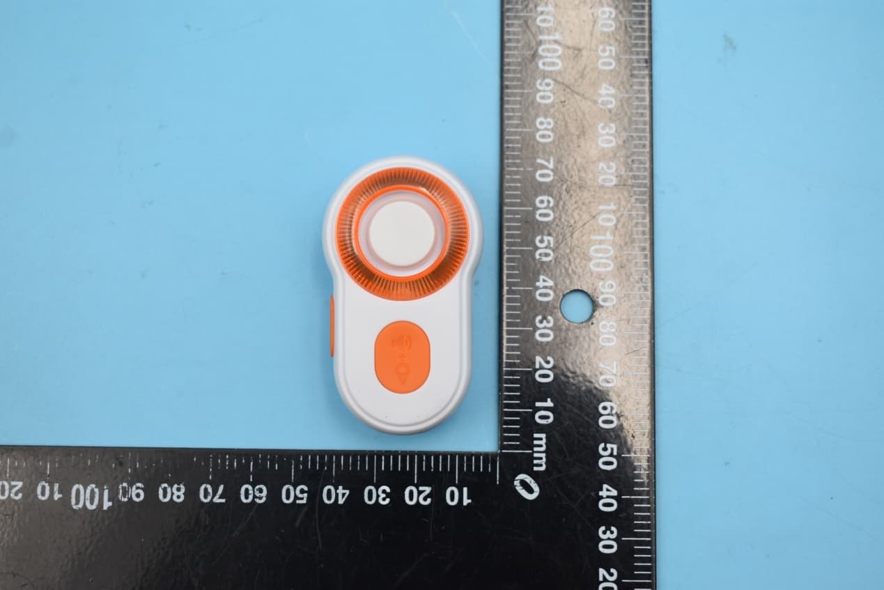
Jan 11, 2020Bluetooth Personal Alarm
Equipment Class
DTS - Digital Transmission System
N9KSMARTMA0136
Dec 10, 2015MaceAlert Smart Panel
Equipment Class
DTS - Digital Transmission System
N9KSMARMA136TX
Dec 10, 2015Keychain Remote Control
Equipment Class
DSC - Part 15 Security/Remote Control Transmitter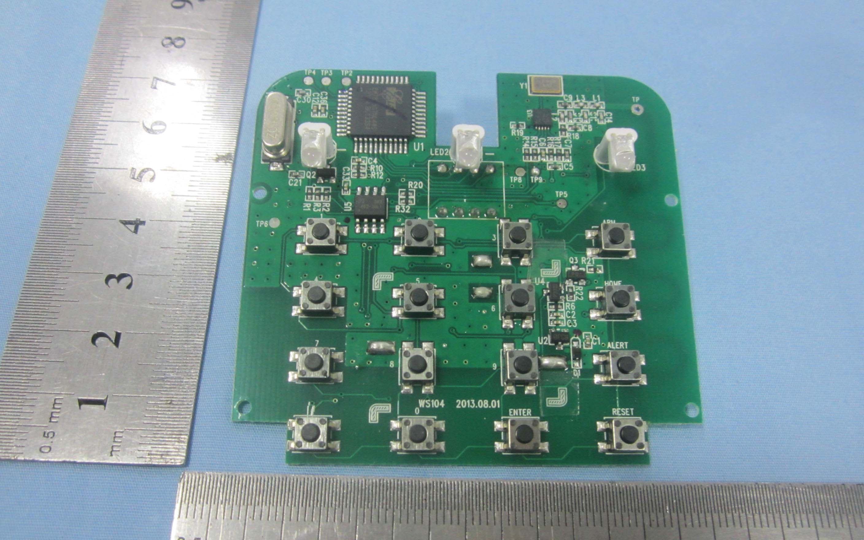
N9KSMARTWS104
Nov 14, 2013KEY PAD CONTROL
Equipment Class
DSC - Part 15 Security/Remote Control Transmitter
N9KGTOF3100
Jul 08, 2013GTO ACCESS WIRELESS ESTATE INTERCOM
Equipment Class
DXX - Part 15 Low Power Communication Device Transmitter