N9N-QD-7168Car Audio and Video Navigation System
Shenzhen QIAN Electronics Technology Co., Ltd.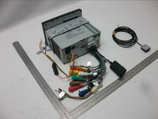
Click to zoom
Application Details
- Equipment Class
- DXX - Part 15 Low Power Communication Device Transmitter
- Date of Grant
- May 29, 2012
- Application Purpose
- Original Equipment
- Date of Application
- May 29, 2012
- Equipment Note
- Car Audio and Video Navigation System
- Frequency Range
- 2402.00000000 - 2480.00000000
- Country
- China
Documents & Files
Document Text
Text extracted from the exhibit documents filed with the FCC. Open a document above to read the original.
Users Manual
Operation and Installation Manual Models: M3-LCD and M4-LCD AM / FM / WB Stereo Receiver with Disc Player and Touch Screen Controls N A V Please carefully read all of the information in this manual. Familiarity with operation and installation proce- dures will help you obtain the best possible performance from your new AM/FM/WB Stereo Receiver and Disc Player with Touch Screen Controls. WARNING! To prevent fire or electrical shock hazard, do not expose this product to moisture or remove its cover or bottom screws. No user-serviceable parts inside. Refer servicing to qualified personnel. Introduction 2 Index Warnings and Cautions 3 Button Locations and Functions 4 Remote Control Button Locations and Functions 4-5 Basic Operation 5-6 System Setup Language 6 Setting the Clock 6-7 Radio Setup 7 GPS Setup 7 Brightness Adjustment 7 System Setup 7-8 Calibration Setup 8 Audio Setup 8 Wallpaper Setup (Background) 8 Reset 9 Sound Controls 9-10 Screen Dimmer 10 Wallpaper 10 Radio Operation AM/FM Radio Operations 11-13 Weather Band Operations 14 Disc Operation Disc Warnings 14 Music Disc Operation 15-16 MP3 Operation (DISC, USB and SD CARD) 17-19 Movie Disc Operation 20-23 Movie Disc Setup Menu 24 GPS Navigation GPS Navigation Operation (M4-LCD Only) 25-34 Operation Bluetooth Operation Bluetooth Operation 35-37 Satellite Radio Satellite Radio Setup 38 Satellite Radio Operation 39-43 IPOD Operation IPOD Operation 44-46 Camera Operation Camera Operation 47 Auxiliary Inputs Auxiliary Audio/Video Inputs Operation 48 Operation Installation 49 Speaker Connections 50 Input and Output Connections 51-53 Camera Connections 54 Restart Button 55 Replaceable Fuse 55 Rear SD Card Holder 55 Warranty 56 3 Warnings • The driver should neither watch the display nor operate the system while driving. Watching the display or operating the system will distract the driver from looking ahead of the vehicle and can cause accidents. Always stop the vehicle in a safe location and use the parking brake before watching the display or operating the system. In some states and countries, passengers are also prohibited from watching the display. • Never install the product in a location where it interferes with your field of vision. • This unit has a cooling fan to decrease the internal tem- perature. Do not mount the unit in a place where the cool- ing fan on the unit is blocked. Blocking these openings will inhibit the cooling of the internal temperature and result in damage to the unit. • Use the proper power supply. This product is designed for operation with a negative grounded 12V DC battery system. Never operate this product with other battery systems, especially a 24V DC battery system. If the prod- uct is used with the improper system it may cause a fire or an accident. • Thi s product must be installed and used in accordance with this manual. Any alterations to this product that enables it to be used in any way other than intended or designed could distract the driver and result in an accident causing injury or death. Magnadyne Corporation disclaims any and all liability that may result from failure to install and operate in any other manner in which this unit was intended. •FCC REGULATIONS STATE THAT ANY UNAUTHORIZED CHANGES OR MODIFICATIONS TO THIS EQUIPMENT MAY VOID THE USER’S AUTHORITY TO OPERATE IT. • TO REDUCE THE RISK OF FIRE OR ELECTRIC SHOCK, DO NOT EXPOSE THIS EQUIPMENT TO RAIN OR MOISTURE. • THIS DEVICE IS INTENDED FOR CONTINUOUS OPERATION. • TO REDUCE THE RISK OF FIRE OR ELECTRIC SHOCK AND ANNOYING INTERFERENCE, USE ONLY THE RECOMMENDED ACCESSORIES. Caution • Do not disassemble, modify the unit or attempt to repair the product yourself. If the product needs to be repaired, consult your dealer. • Do not install the unit in a place exposed to direct sunlight or excessive heat or humidity. Avoid places with too much dust or the possibility of water splashing. • Backing Up Your Vehicle Do not backup your vehicle while looking at the monitor. Always look in the direction of your vehicle’s motion. Use the monitor only as an aid in safety confirmation. The actual distance may be different than it appears in the monitor. The range of the image in the monitor is limited. Always be aware that blind spots may exist and not appear at all times on your monitor. The product is intended to assist in safe driving and allows the driver to have a broader field of vision dur- ing backup. You, as the driver, are solely responsible for the safe operation of your vehicle and the safety of your passengers and pedestrians, and abiding all state and local traffic regulations. Do not use any features of this system to the extent it distracts you from safe driving. Your first priority while driving should always be the safe operation of your vehicle. Magnadyne will not accept any responsibility whatsoever for accidents and/or injuries resulting from failure to observe these precautions or safety instructions. Liquid Crystal Panel • Any harsh impacts may damage the liquid crystal panel. • Usage temperature range: 32 0 F to 104 0 F. When the temperature is very cold or very hot, the image may not appear clearly or may move slowly. Also, movement of the image may seem to be out of synchronization or the image quality may decline in such environments. Note that this is not a malfunction or problem. • Sudden changes in the temperature inside the vehicle such as those which occur immediately after the vehicle’s air conditioner or heater has been turned on may cause the inside of the liquid crystal panel to cloud over due to water vapor or it may cause condensation (droplets of water) to form and, as a result, the panel may not work properly. Do not use the unit while these symptoms are evident. Instead, leave the unit standing for about an hour, and then resume or start use. • If the screen of this unit is dirty, wipe the dirt off with a cloth moistened with a mild cleaner. Note: Applying spray cleaner directly to the unit may affect its mech…
Text truncated - open the document above for the full version.
External Photos
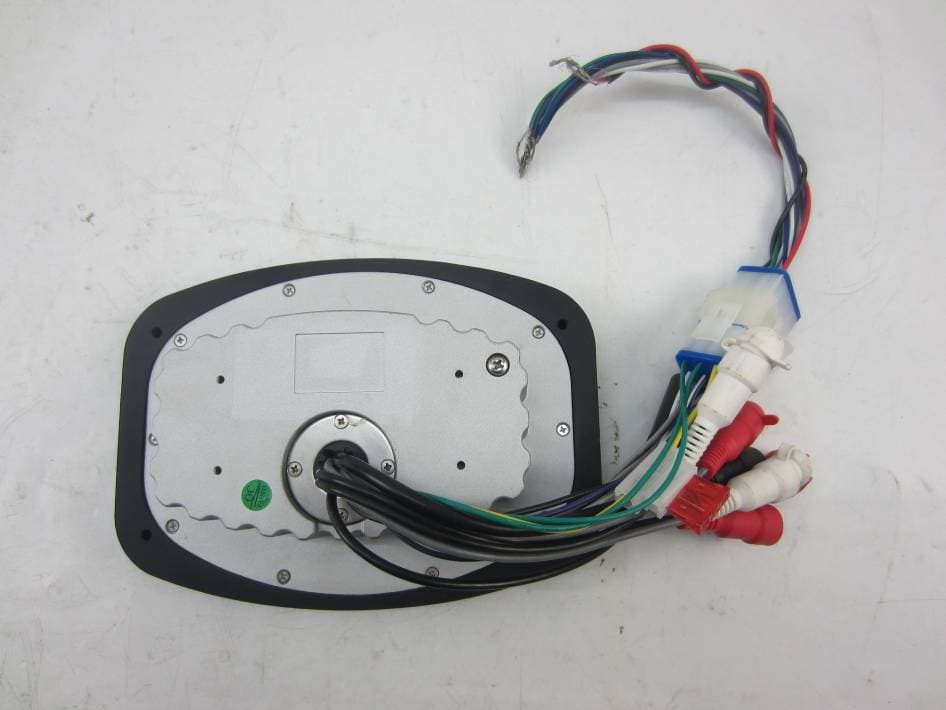
FRONT VIEW OF SAMPLE BACK VIEW OF SAMPLE UP VIEW OF SAMPLE DOWN VIEW OF SAMPLE LEFT VIEW OF SAMPLE RIGHT VIEW OF SAMPLE PHOTO OF THE ENTIRE SAMPLE-1 PHOTO OF THE ENTIRE SAMPLE-2
ID Label/Location Info
FCC ID: N9N-QD-7168 This device complies with Part 15 of the FCC Rules. Operation is subject to the following two conditions: (1) this device may not cause harmful interference, and (2) this device must accept any interference received, including interference that may cause undesired operation.
Internal Photos
INTERNAL PHOTO OF SAMPLE – 1 INTERNAL PHOTO OF SAMPLE – 2 INTERNAL PHOTO OF SAMPLE – 3 INTERNAL PHOTO OF SAMPLE –4 INTERNAL PHOTO OF SAMPLE –5 INTERNAL PHOTO OF SAMPLE –6 INTERNAL PHOTO OF SAMPLE –7 INTERNAL PHOTO OF SAMPLE –8 INTERNAL PHOTO OF SAMPLE –9 INTERNAL PHOTO OF SAMPLE –10 INTERNAL PHOTO OF SAMPLE –11 INTERNAL PHOTO OF SAMPLE –12 INTERNAL PHOTO OF SAMPLE –13 INTERNAL PHOTO OF SAMPLE –14 INTERNAL PHOTO OF SAMPLE –15 INTERNAL PHOTO OF SAMPLE –16 INTERNAL PHOTO OF SAMPLE –17 INTERNAL PHOTO OF SAMPLE –18 INTERNAL PHOTO OF SAMPLE –19 INTERNAL PHOTO OF SAMPLE –20 INTERNAL PHOTO OF SAMPLE –21 INTERNAL PHOTO OF SAMPLE –22 INTERNAL PHOTO OF SAMPLE –23 INTERNAL PHOTO OF SAMPLE –24
Test Report
FCC 47 CFR PART 15 SUBPART C TEST REPORT For Applicant: Shenzhen QIAN Electronics Technology Co., Ltd. Address: Building 5, High Technology Hong-Erh Industrial, Shengping Road, Longgang District, Shenzhen, China Product Name: Car Audio and Video Navigation System Model Name: QD-7168 Brand Name: N/A FCC ID: N9N-QD-7168 Report No.: MTE/DAL/D12050537 Date of Issue: May 16, 2012 Issued by : Most Technology Service Co., Ltd. Address : No.5, Langshan 2nd Road, North District, Hi-tech Industrial Park, Nanshan, Shenzhen, Guangdong, China Tel : 86-755-8617 0306 Fax : 86-755-8617 0310 The report consists 28 pages in total. It may be duplicated completely for legal use with the approval of the applicant. It should not be reproduced except in full, without the written approval of our laboratory. The client should not use it to claim product endorsement by MOST. The test results in the report only apply to the tested sample. The test report shall be invalid without all the signatures of testing engineers, reviewer and approver. FCC ID: N9N-QD-7168 Report No.: MTE/DAL/D12050537 Page 2 of 28 TABLE OF CONTENTS 1. VERIFICATION OF CONFORMITY ............................................................................................................... 3 2. GENERAL INFORMATION ............................................................................................................................ 4 2.1 Product Information ...................................................................................................................................... 4 2.2 Objective ...................................................................................................................................................... 5 2.3 Test Standards and Results .......................................................................................................................... 5 2.4 Environmental Conditions............................................................................................................................. 5 3. TEST FACILITY.............................................................................................................................................. 6 3.1TEST FACILITY............................................................................................................................................. 6 3.2 GENERAL TEST PROCEDURES ................................................................................................................ 6 3.3 FCC PART 15.205 RESTRICTED BANDS OF OPERATIONS..................................................................... 7 4. SETUP OF EQUIPMENT UNDER TEST ....................................................................................................... 8 4.1 SUPPORT EQUIPMENT.............................................................................................................................. 8 4.2 TEST EQUIPMENT LIST ............................................................................................................................. 9 5. 47 CFR Part 15C 15.249 Requirements....................................................................................................... 10 5.1 Spurious Emission Test .............................................................................................................................. 10 5.1.1 Requirement............................................................................................................................................ 10 5.1.2 Test Description ........................................................................................................................................11 5.1.3 Test Description ....................................................................................................................................... 12 5.1.4 Test Result............................................................................................................................................... 13 5.2 Band Edge ................................................................................................................................................. 19 5.2.1 Requirement............................................................................................................................................ 19 5.2.2 Test Description ....................................................................................................................................... 19 5.2.3Test Result................................................................................................................................................ 19 5.3 LINE CONDUCTED EMISSION TEST (NOT APPLICABLE) ..................................................................... 22 5.3.1. LIMITS OF LINE CONDUCTED EMISSION TEST ................................................................................ 22 5.3.2. BLOCK DIAGRAM OF TEST SETUP..................................................................................................... 22 5.3.3. PRELIMINARY PROCEDURE OF LINE CONDUCTED EMISSION TEST ............................................ 23 5.3.4. FINAL PROCEDURE OF LINE CONDUCTED EMISSION TEST .......................................................... 23 5.3.5. Test result ............................................................................................................................................... 23 5.4 20 dB Bandwidth ........................................................................................................................................ 24 5.4.1 Definition ................................................................................................................................................. 24 5.4.2 Block Diagram Of Test Setup .................................................................................................................. 24 5.4.3 Test Result...............................................…
Text truncated - open the document above for the full version.
Test Setup Photos
RE TEST SETUP SPURIOUS EMISSION TEST SETUP
Contact Information
Applicant
Li Gang(Manager)
Test Firm
Most Technology Service Co., Ltd.Mark Wen
Technical Specifications
| # | Rule Parts | Frequency Range | Power Output |
|---|---|---|---|
| 1 | 15C | 2.40 GHz - 2.48 GHz | - |
Other Applications from Shenzhen QIAN Electronics Technology Co., Ltd.
N9N-SP3
Jan 27, 2016SPA DOCK SP3
Equipment Class
DTS - Digital Transmission System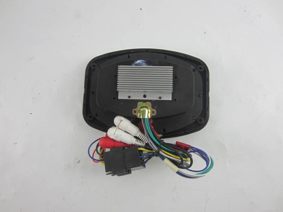
N9N-SP1
Nov 22, 2015SPA DOCK SP1
Equipment Class
DTS - Digital Transmission System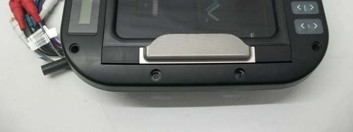
N9N-QU-1209
Jul 04, 2013Media Center
Equipment Class
DXX - Part 15 Low Power Communication Device Transmitter