N9N-SP1SPA DOCK SP1
Shenzhen QIAN Electronics Technology Co., Ltd.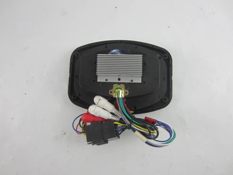
Click to zoom
Application Details
- Equipment Class
- DTS - Digital Transmission System
- Date of Grant
- Nov 22, 2015
- Application Purpose
- Original Equipment
- Date of Application
- Nov 22, 2015
- Equipment Note
- SPA DOCK SP1
- Frequency Range
- 2402.00000000 - 2480.00000000
- Country
- China
Documents & Files
Document Text
Text extracted from the exhibit documents filed with the FCC. Open a document above to read the original.
Users Manual
Operation / Installation Manual Bluetooth AM/FM Entertainment Center SP-1 MUTEAPS FM/AM MODE VOLVOL 1 23456 ALARM CLOCK DIMMER SET MENU 3 Please take the time to read all of the information in this manual. Familiarity with operation and installation procedures will help you obtain the best possible performance from your new Entertainment Center. WARNING! • FCC REGULATIONS STATE THAT ANY UNAUTHORIZED CHANGES OR MODIFICATIONS TO THIS EQUIPMENT MAY VOID THE USER’S AUTHORITY TO OPERATE IT. • THIS DEVICE IS INTENDED FOR CONTINUOUS OPERATION. • TO REDUCE THE RISK OF FIRE OR ELECTRIC SHOCK AND ANNOYING INTERFERENCE, USE ONLY THE RECOMMENDED ACCESSORIES. Introduction Index Button Locations and Functions ..................................................... 4-5 General Operation ................................................................ 6 Sound Controls .................................................................. 7-8 Speaker Selection ................................................................ 8 Clock and Alarm Operations ........................................................ 9 Radio Operations ................................................................. 10-11 External AUX Rear Audio Input ...................................................... 11 Bluetooth Operations .............................................................. 12 Installation ...................................................................... 13 Wiring ......................................................................... 14 4 MUTEAPS FM/AM MODE VOLVOL 1 23456 ALARM CLOCK DIMMER SET MENU Button Locations and Functions 1. Power and Mute Button: Power Button: Press to turn the entertainment center on. Press and hold the button for 3 seconds to turn the unit off. Mute Button: Press to mute sound. Press again to restore. 2. Bluetooth and APS Button: Bluetooth Selection Button: Press to choose Bluetooth input mode. Bluetooth device must be paired prior to use. APS Button: Press and hold for radio Automatic Preset Scan and Storage. 3. Mode Button and Alarm Button: Mode Button: Press to toggle between RADIO, BT AUDIO (Bluetooth) and AUX. Alarm Button: Press and hold to enter set Alarm mode. (See Setting the Alarm section for details). 4. FM/AM Radio Selection: Press to choose Radio mode. Sequential presses will select radio bands: FM1, FM2, FM3, AM1 and AM2. 5. Radio Station Recall Buttons (1-3): Press and release to recall preset radio stations. Press and hold to memorize a selected station as a numbered preset. Bluetooth mode (available functions are dependent upon the specific Bluetooth audio device and the audio application): : Press to pause track, press again to resume. 6. Clock and Dimmer Button: DIMMER Button: Short press to toggle between LED High, LED Mid and LED Low. CLOCK Button: Press and hold to enter set clock mode. (See Setting the Clock section for details). 7. Radio Station Recall Buttons (4-6): Press and release to recall preset radio stations. Press and hold to memorize a selected station as a numbered preset. 8. Volume Down Button: Press to decrease volume level. Also use for selection down through adjustments within the SET/MENU options: sound controls, display, area location, speaker selection and alarm. 9. Volume Up Button: Press VOL to increase volume level. Also use for selection up through adjustments within the SET/MENU options: sound controls, display, area location, speaker selection and alarm. 10. Seek Down Button : Radio Mode: Short press to automatically seek for next lower tunable frequency. Press and hold to move into manual tuning mode. Bluetooth Mode: Press to search for the beginning of the previous track. 7 12 3 8 10 5 12 13 4 6 9 11 5 11. Seek Up Button : Radio Mode: Short press to automatically seek for next higher tunable frequency. Press and hold to move into manual tuning mode. Bluetooth Mode: Press to search for the beginning of the next track. 12. SET / MENU Button: Short press to enter and then short presses to toggle between sound adjustments: Bass, Treble, Balance, Fader then DSP: Pop/Rock/ Classic, Boost On/Off and then back to Volume. Use the VOL or VOL to make adjustments. Press and hold to enter 2nd menu and then short press to toggle between Area USA1/ AREA USA2/AREA EUR, Speaker A & B Selection, STEREO / MONO, ALARM ON/ OFF and DISP ON/OFF. Use the VOL or VOL to make adjustments. See desired feature adjustment selection for operation details. 13. Reset Button: To reset the unit to its factory settings use a pointed object like a ball point pen to press the RESET button. Button Locations and Functions (Continued) 6 MUTEAPS FM/AM MODE VOLVOL 1 23456 ALARM CLOCK DIMMER SET MENU MUTEAPS FM/AM MODE VOLVOL 1 23456 ALARM CLOCK DIMMER SET MENU MUTEAPS FM/AM MODE VOLVOL 1 23456 ALARM CLOCK DIMMER SET MENU MUTEAPS FM/AM MODE VOLVOL 1 23456 ALARM CLOCK DIMMER SET MENU MUTEAPS FM/AM MODE VOLVOL 1 23456 ALARM CLOCK DIMMER SET MENU General Operations Power On: Press the / MUTE button to turn the unit on. Power Off: Press the / MUTE button for 3 seconds to turn the unit off. Mute: A short press of the / MUTE button will mute the audio. Selecting a Play Source: Press the MODE button to selected either: “RADIO”, “AUX” or “BT AUDIO” Dimming the Display: Press the DIMMER button to select from the 3 levels of brightness for the display area: “LED LOW”, “LED MID” or “LED HIGH” Priority Clock Display Selection: Press and hold the SET/MENU button until A_SPK ON appears. Short press the same button until “DISP OFF” or “DISP ON” appears on the screen. Immediately press Volume buttons to toggle to either of the 2 desired screen appearances: 1. DISP ON: Screen will remain on current time display. 2. DISP OFF: Screen will display current radio station in RADIO mode, track information in BT Audio mode or “AUX” in AUX mode. 7 MUTEAPS FM/AM MODE VOLVOL 1 23456 ALARM CLOCK DIMMER SET MENU Sound Controls Bass: Press the SET/MENU. The first sound mode adjustment displayed will be “BAS…
Text truncated - open the document above for the full version.
Cover Letter(s)
MET Laboratories TCB - Samples Agent Authorization Letter 2015-11-09 MET Laboratories, Inc. 914 West Patapsco Avenue Baltimore, MD 21230 RE: LETTER OF AGENT AUTHORIZATION To Whom It May Concern: We, the undersigned, hereby authorize Most Technology Service Co., Ltd. to act on our behalf in all matters relating to application for equipment authorization, including the signing of all documents relating to these matters. We also hereby certify that no party to the application authorized hereunder is subject to the denial of benefits, including FCC benefits, pursuant to Section 5301 of the Anti-Drug Abuse Act of 1988, 21 U.S.C.853(a). This agreement expires one year from the current date. Sincerely, Name: Gang Li Position: Manager Company Name: Shenzhen QIAN Electronics Technology Co., Ltd. Address: Building 5, High Technology Hong-Erh Industrial, Sheng Ping Road, Long Gang District, Shenzhen, Guangdong, China E-Mail: [email protected]
Cover Letter(s)
MET Laboratories TCB - Samples Long Term Confidentiality Request Letter 2015-11-09 MET Laboratories, Inc. 914 West Patapsco Avenue Baltimore, MD 21230 RE: CONFIDENTIALITY REQUEST FOR (SPA DOCK SP1/ SP1) To Whom It May Concern: This letter serves as an official request for confidentiality under sections 0.457 and 0.459 of CFR 47. We have requested that the - e.g. Block diagram - e.g. SCH - e.g. Operational Description required to be submitted with this application be permanently withheld from public review. SPECIFY REASON FOR REQUEST (i.e. the above documents are company proprietary information that could never get into the possession of your competition). Please contact me if there is any information you may need. Sincerely, Name: Gang Li Position: Manager Company Name: Shenzhen QIAN Electronics Technology Co., Ltd. Address: Building 5, High Technology Hong-Erh Industrial, Sheng Ping Road, Long Gang District, Shenzhen, Guangdong, China E-Mail: [email protected]
External Photos
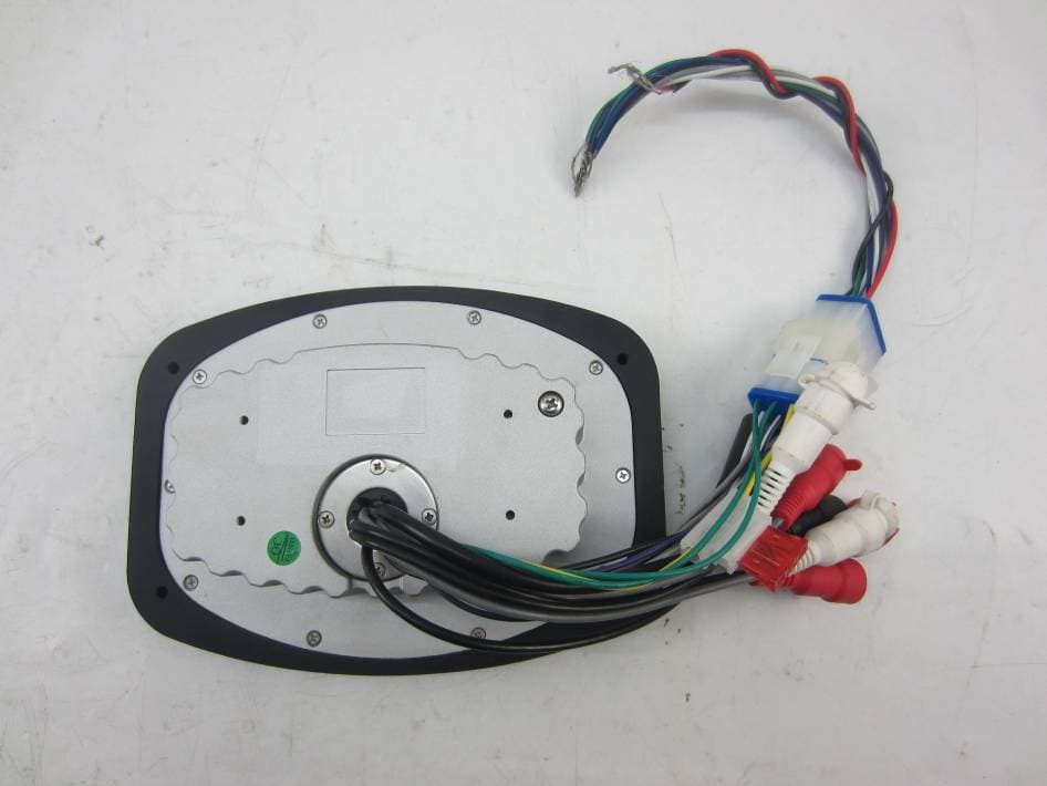
Model No.: SP1 FRONT VIEW OF SAMPLE BACK VIEW OF SAMPLE Model No.: SP1 LEFT VIEW OF SAMPLE RIGHT VIEW OF SAMPLE Model No.: SP1 TOP VIEW OF SAMPLE BOTTOM VIEW OF SAMPLE
ID Label/Location Info
Label Label location
Test Report
Report No.: MTE/HNZ/A15101405 Page 1 of 36 TEST REPORT For Applicant : Shenzhen QIAN Electronics Technology Co., Ltd. Address : Building 5, High Technology Hong-Erh Industrial Sheng Ping Road, Long Gang District ,Shenzhen, China. Product Name : SPA DOCK SP1 Model Name: SP1 Brand Name : Linear series FCC ID : N9N-SP1 Report No. : MTE/HNZ/A15101405 Date of Issue : Nov. 03, 2015 Issued by :Most Technology Service Co., Ltd. Address : No.5, 2nd Langshan Road, North District, Hi-tech Industrial Park, Nanshan, Shenzhen, Guangdong, China Tel : 86-755-8602 6850 Fax : 86-755-2601 3350 The report consists 36 pages in total. It may be duplicated completely for legal use with the approval of the applicant. It should not be reproduced except in full, without the written approval of our laboratory. The clien t should not use it to claim product endorsement by MOST. The test results in the report only apply to the tested sample. The test report shall be invalid without all the signatures of testing engineers, reviewer and approver. Report No.: MTE/HNZ/A15101405 Page 2 of 36 TABLE OF CONTENTS 1. VERIFICATION OF CONFORMITY.......................................................................................... 4 2. GENERAL INFORMATION....................................................................................................... 5 2.1 Product Information ................................................................................................................ 5 2.2 Objective ................................................................................................................................ 5 2.3 Test Standards and Results .................................................................................................... 6 2.4 Environmental Conditions....................................................................................................... 6 3. TEST METHODOLOGY ........................................................................................................... 7 3. 1TEST FACILITY...................................................................................................................... 7 3.2 GENERAL TEST PROCEDURES .......................................................................................... 7 4. SETUP OF EQUIPMENT UNDER TEST.................................................................................. 8 4.1 SETUP CONFIGURATION OF EUT....................................................................................... 8 4.2 SUPPORT EQUIPMENT ........................................................................................................ 8 4.3 TEST EQUIPMENT LIST........................................................................................................9 5. 47 CFR Part 15 C Requirements............................................................................................ 10 5.1 RF EXPOSURE.................................................................................................................... 10 5.1.1 Applicable Standard........................................................................................................... 10 5.1.2 Result: ............................................................................................................................... 10 5.2 ANTENNA REQUIREMENT ..................................................................................................11 5.2.1 Applicable Standard............................................................................................................11 5.2.2 Evaluation Criteria ..............................................................................................................11 5.2.3 Result: Compliance. ...........................................................................................................11 5.3 AC Power Line Conducted Emission .................................................................................... 12 5.3.1Requirement....................................................................................................................... 12 5.3.2 Block Diagram of Test Setup ............................................................................................. 12 5.3.3 Test procedure................................................................................................................... 12 5.3.4 Test Result......................................................................................................................... 12 5.4 Radiated Emission ............................................................................................................... 13 5.4.1Requirement....................................................................................................................... 13 5.4.2 Test Configuration.............................................................................................................. 13 5.4.3 Test Procedure: ................................................................................................................. 14 5.4.4 Test Result.............................................................................................................. ........... 15 5.5 Conducted Peak Output Power ............................................................................................ 22 5.5.1 Requirement...................................................................................................................... 22 5.5.2 Block Diagram of Test Setup ............................................................................................. 22 5.5.3 Test Procedure .................................................................................................................. 22 5.5.4 Test Result......................................................................................................................... 22 5.6 6dB Emission Bandwidth................................................................…
Text truncated - open the document above for the full version.
Test Setup Photos
Model No.: SP1 CONDUCTED EMISSION TEST SETUP RE TEST SETUP Model No.: SP1 RE TEST SETUP
Contact Information
Applicant
Li Gang(Manager)
Non-Technical Contact
Most Technology Service Co.,Ltd.Mark Wen
[email protected]86-755-86026850
Test Firm
Most Technology Service Co., Ltd.Mark Wen
Technical Specifications
| # | Rule Parts | Frequency Range | Power Output |
|---|---|---|---|
| 1 | 15C | 2.40 GHz - 2.48 GHz | 3.20 mW |
Other Applications from Shenzhen QIAN Electronics Technology Co., Ltd.
N9N-SP3
Jan 27, 2016SPA DOCK SP3
Equipment Class
DTS - Digital Transmission System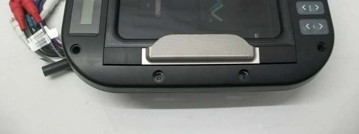
N9N-QU-1209
Jul 04, 2013Media Center
Equipment Class
DXX - Part 15 Low Power Communication Device Transmitter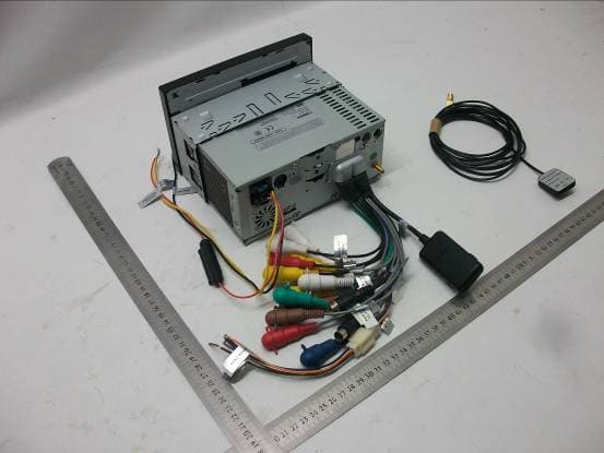
N9N-QD-7168
May 29, 2012Car Audio and Video Navigation System
Equipment Class
DXX - Part 15 Low Power Communication Device Transmitter