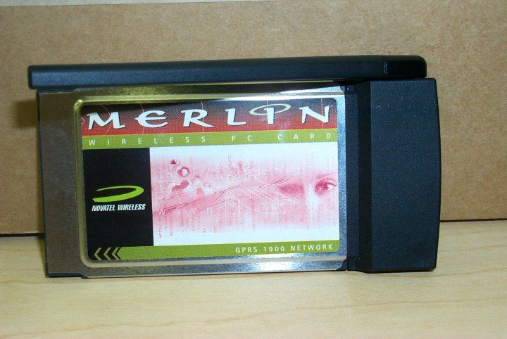
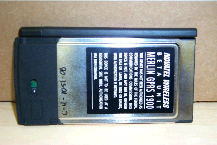
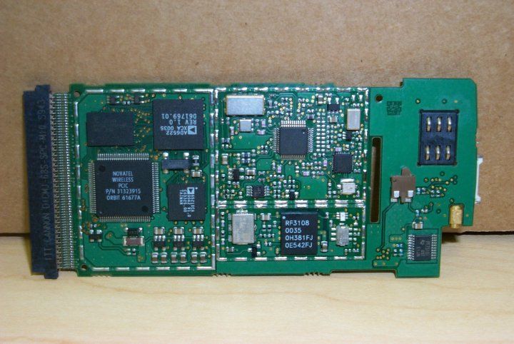
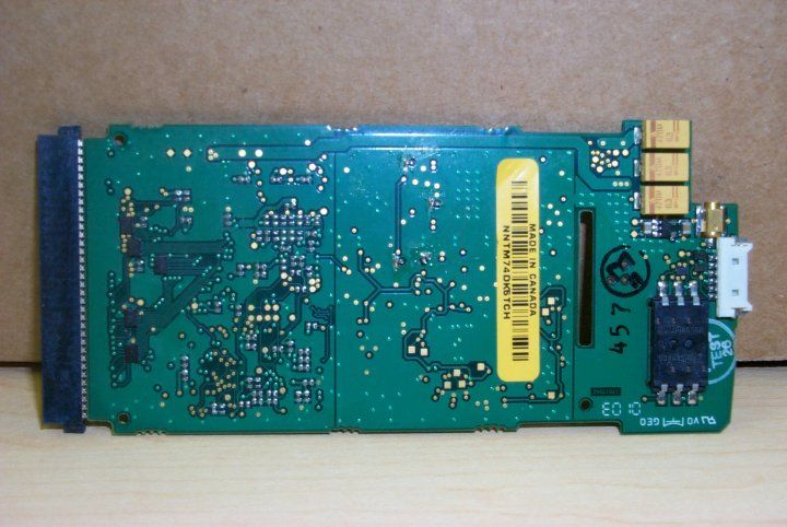
NBZNRM-G2000PCMCIA card for use with Laptop computers
Novatel Wireless, Inc.
Click to zoom
Application Details
- Equipment Class
- TNB - Licensed Non-Broadcast Station Transmitter
- Date of Grant
- May 09, 2001
- Application Purpose
- Original Equipment
- Date of Application
- Mar 03, 2001
- Equipment Note
- PCMCIA card for use with Laptop computers
- Frequency Range
- 1850.00000000 - 1910.00000000
- Company
- Novatel Wireless, Inc.
- Country
- United States
Documents & Files
Document Text
Text extracted from the exhibit documents filed with the FCC. Open a document above to read the original.
Users Manual
Revision 0.A 1 GPRS for Voicestream User’s Manual Revision 0.A 2 Table of Contents Purpose 4 Overview 4 Mouse-Over 4 Right-Click 5 Shortcut and Accelerator Keys 6 The Modem Manager Components 6 About GPRS Modem Manager Dialog Box.................................................6 Basic View...............................................................................................7 Connect To Dialog Box 9 Connecting Using GPRS Modem Manager 9 Detailed Status Report Dialog Box 10 Detailed View 11 Error Messages 14 GPRS Connect Confirmation Dialog Box 14 GSM Connect Confirmation Dialog Box 15 Menu Bar 15 Modem Configuration Dialog Box 21 Modem Properties Dialog Box 22 Title Bar 23 Tray Icon 24 User Interaction During Connection 24 Connecting Using Dial-Up Networking Connection Icons 24 Revision 0.A 3 Safety and Regulatory Notices SAFETY WARNING This product is not to be used in any environment where radio frequency equipment is prohibited or restricted in its use. This includes aircraft/airports, hospitals, and other sensitive electronic areas. To ensure that your modem is deactivated you should remove it from your computer under the above conditions. SAFETY WARNING Under extended operation the Merlin for GPRS modem will generate a noticeable amount of heat. Like all PC Cards, the modem generates heat during normal operations and is also heated by the host computer. For this reason it is recommended that you allow the modem to cool down after extensive operation so that it is cool to the touch when you remove it from your computer. REGULATORY NOTICES Federal Communications Commission Radio Frequency Interference Statement This equipment has been certified to comply within the limits of a class B digital device pursuant to part 15 of the FCC Rules. These limits are designed to provide reasonable protection against harmful interference in residential situations. This equipment generates, uses, and can radiate radio frequency energy, and, if not properly installed and used in accordance with the instructions, may cause harmful interference to radio or television reception, which can be determined by turning the equipment on and off. You are encouraged to try to correct the interference by one or more of the following measures: • Reorient or relocate the receiving antenna of the television, radio or cordless telephone. • Increase the separation between the equipment and the receiver. • Connect the equipment to an outlet on a circuit different from that to which the receiver is connected. • Consult the dealer or an experienced radio/television technician for additional suggestions. FCC guidelines state that the antenna should be more than 17 mm (0.7 “) from all persons. FCC ID: NBZNRM-G2000 Revision 0.A 4 Purpose This main window is intended to allow the user, during normal operation, to immediately and definitively determine the state of the modem. This will allow the user to confirm the modem is in the expected state or trigger the user to take action to change the state of the modem as required. Any fields that are only required for diagnostics or troubleshooting will be found deeper in the application to avoid creating an overly complex main interface. The purpose of this document is to provide detailed information regarding the appearance and operation of the user interface for the GPRS Modem Manager application developed for Windows 95, 98, NT, ME, and 2000. The Software Engineering group will attempt to meet the specifications outlined in this document when developing the application. Overview The GPRS Modem Manager application provides the user with both control over the modem’s operation and feedback about the status of the modem. The basic information and controls needed during day-to-day operation will be quickly and easily accessible. Less frequently used functionality will still be easy to access but should not get in the way or obstruct the user’s view of essential status information. The main window will be split into two sections, one that provides information about and control over the modem’s connection to the network, and another section that displays other necessary status information. The second section will have two views, which the user will be able to switch between using the button provided. The first, basic view will provide the minimal amount of status information required by the user. This view is provided to help keep the application simple, but also to keep its dimensions small for users who wish to leave the GPRS Modem Manager program open all the time. The second, detailed view will display the fields that a more advanced user may find useful. Whenever the application is re-launched, the most recently used view will be displayed. Mouse-Over When the user leaves the cursor over the icon, a small tool tip type window will be displayed showing the connection status. The possible strings to display for the connection status are listed in a later section. Revision 0.A 5 Right-Click For a DUN connection, right-clicking on the icon will open the following menu. For a NIC connection, right-clicking on the icon will open this menu. The operation of the menu commands is detailed in the table below. Command Implementation Open Modem Manager When selected, the GPRS Modem Manager’s main window is opened with the most recently used view displayed. This command can be accessed by using Alt+o. Connect When selected, the modem attempts to intiate a data session. When a data session is already open, this command is disabeled. This command is only displayed for a DUN connection. This command can be accessed by using Alt+c. Disconnect When selected, the modem closes the data session. When a data session is not open, this command is disabled. This command in only displayed for a DUN connection. This command can be accessed by using Alt+d. Suspend When selected, the data session is closed. When a data session is open, this command is disabled. Resume When selected, the modem attempt…
Text truncated - open the document above for the full version.
Users Manual
Revision 0.A 3 Safety and Regulatory Notices SAFETY WARNING This product is not to be used in any environment where radio frequency equipment is prohibited or restricted in its use. This includes aircraft/airports, hospitals, and other sensitive electronic areas. To ensure that your modem is deactivated you should remove it from your computer under the above conditions. SAFETY WARNING Under extended operation the Merlin for GPRS modem will generate a noticeable amount of heat. Like all PC Cards, the modem generates heat during normal operations and is also heated by the host computer. For this reason it is recommended that you allow the modem to cool down after extensive operation so that it is cool to the touch when you remove it from your computer. REGULATORY NOTICES Federal Communications Commission Radio Frequency Interference Statement This equipment has been certified to comply within the limits of a class B digital device pursuant to part 15 of the FCC Rules. These limits are designed to provide reasonable protection against harmful interference in residential situations. This equipment generates, uses, and can radiate radio frequency energy, and, if not properly installed and used in accordance with the instructions, may cause harmful interference to radio or television reception, which can be determined by turning the equipment on and off. You are encouraged to try to correct the interference by one or more of the following measures: • Reorient or relocate the receiving antenna of the television, radio or cordless telephone. • Increase the separation between the equipment and the receiver. • Connect the equipment to an outlet on a circuit different from that to which the receiver is connected. • Consult the dealer or an experienced radio/television technician for additional suggestions. FCC ID: NBZNRM-G2000
Cover Letter(s)
March 4, 2001 Federal Communicatio ns Co mmission 7435 Oakland Mills Road Columbia, MD 21036 Re: Novatel Application for Certification Gentle me n: Submitted herewith is an application for a Novatel Wireless pcmcia modem card for use in laptop computers. It provides a wireless connection to service providers operating under Part 24 of the FCC Rules using the GS M for mat. Sincerely, Phillip Inglis TRP/Cetecom bvba
Cover Letter(s)
May 1, 2001 RF Exposure This transmitter has a nominal power output of slightly less the 1-Watt. In this application (pcmcia card to be inserted in a laptop computer), the Commission considers it to be a mobile device and typically requests information be provided to the user that he should maintain an operating distance of 20 cm from the body. Novatel has decided that in lieu of placing this warning statement in the manual they are providing two SAR test reports showing the equipment does not exceed the RF exposure limits for distances less than 20 cm spacing. The transmitter has two modes of operation. Nominal GSM operation uses 1 time slot per frame for transmission. An SAR report has been provided for this type of operation. In order to increase data throughput, this transmitter can operate in a mode that uses two time slots. A test report for this mode of operation is also provided. Phillip Inglis Age nt for Novatel
ID Label/Location Info
M GPRS 1900 MHz FCC ID: NBZNRM-G2000 MODEL: NRM-G2000 THIS PRODUCT COMPLIES WITH PART 15 OF THE FCC RULES. OPERATION IS SUBJECT TO THE CONDITION THAT THIS DEVICE DOES NOT CAUSE HARMFUL INTERFERENCE
RF Exposure Info
March 4, 2001 RF Exposure This transmitter has a nominal power output of slightly less the 1 Watt. In this application (pcmcia card to be inserted in a laptop computer), the Commission considers it to be a mobile device and typically requests information be provided to the user that he should maintain an operating distance of 20 cm from the body. Novatel has decided that in lieu of placing this warning statement in the manual, they will provide SAR information to the FCC and is now in the process of having the test conducted. The SAR data will be available shortly and will be provided as soon as it arrives. Phillip Inglis Age nt for Novatel
RF Exposure Info
A 1365 Adams Court, Menlo Park, CA 94025 Novatel Wireless Technologies, LTD Model No: NRM-G2000Date of Test: February 28, 2001 FCC ID: NBZNRM-G2000 Report # 204219811FCC Part 2 SAR Evaluation Table of Contents 1.0Job description...........................................................................................................2 1.1......Client Information.............................................................................................2 1.2......Equipment under test (EUT).............................................................................2 2.0Test plan reference.....................................................................................................3 2.1......System test configuration..................................................................................3 2.1.1System block diagram & Support equipment.........................................3 2.2......Test Position.....................................................................................................4 2.3......Test Condition..................................................................................................6 2.4......Modifications required for compliance..............................................................6 2.5......Additions, deviations and exclusions from standards.........................................6 3.0SAR EVALUATION..................................................................................................7 3.1...... SAR Limits......................................................................................................7 3.2......Configuration Photographs...............................................................................8 3.3......System Verification........................................................................................12 3.4......Evaluation Procedures....................................................................................12 4.0 Test Results................................................................................................................13 5.0EQUIPMENT...........................................................................................................15 5.1 Equipment List...............................................................................................15 5.2......Tissue Simulating Liquid................................................................................16 5.3......E-Field Probe Calibration...............................................................................18 5.5......Measurement Uncertainty...............................................................................18 5.5......Measurement Traceability...............................................................................18 6.0WARNING LABEL INFORMATION - USA.........................................................19 7.0.....REFERENCES.........................................................................................................20 APPENDIX A - SAR Evaluation Data................................................................................21 APPENDIX B - E-Field Probe Calibration Data................................................................23 8.0Document History.....................................................................................................29 A 1365 Adams Court, Menlo Park, CA 94025 Novatel Wireless Technologies, LTD Model No: NRM-G2000Date of Test: February 28, 2001 FCC ID: NBZNRM-G2000 Report # 204219812FCC Part 2 SAR Evaluation 1.0 Job description 1.1 Client Information The EUT has been tested at the request of: Company:Novatel Wireless Technologies, LTD. Address:Suite 200, 6715 – 8 th Street NE Calary, Alberta Zip T2E7H7 Canada Name of contact:Mr. Kevin Goodfellow Telephone: +1 (404) 2954809 1.2 Equipment under test (EUT) Product Descriptions: Equipment PC Card Trade NameNovatel Wireless Technologies, LTD Model No.NRM-G2000 FCC IDNBZNRM-G2000S/N No. Not Labeled Category Portable RF Exposure Uncontrolled Environment Frequency Band (uplink) 1850-1910 System GSM EUT Antenna Description TypeMonopoleConfiguration Removeable 360° Rotation Dimensions10 cm (Length)Gain1 dBi LocationRight Use of Product:Portable personal communications Manufacturer:SAME as above. Production is planned:[X] Yes, [ ] No EUT receive date:February 18, 2001 EUT received condition:Good condition prototype Test start date:February 28, 2001 Test end date:February 28, 2001 A 1365 Adams Court, Menlo Park, CA 94025 Novatel Wireless Technologies, LTD Model No: NRM-G2000Date of Test: February 28, 2001 FCC ID: NBZNRM-G2000 Report # 204219813FCC Part 2 SAR Evaluation 2.0Test plan reference FCC rule part 2.1093, FCC Docket 96-326 & Supplement C to OET Bulletin 65 2.1System test configuration 2.1.1System block diagram & Support equipment EUT IBM Laptop A 1365 Adams Court, Menlo Park, CA 94025 Novatel Wireless Technologies, LTD Model No: NRM-G2000Date of Test: February 28, 2001 FCC ID: NBZNRM-G2000 Report # 204219814FCC Part 2 SAR Evaluation 2.2Test Position Three test configurations were used to show compliance with the FCC RF human exposure requirements. In all configurations, the NRM-G2000 was configured for testing in a typical fashion (as a customer would normally use it). Due to the application and usage of the product, SAR measurements with the human head region are not necessary. Table 1 below describes the setup and condition: Table 1, Equipment Setup ConfigurationDescription A • Antenna in horizontal position, 17 mm distance from antenna to Phantom. • Simulating close proximity of human body. B • Antenna in horizontal position, 17 mm distance from antenna to Phantom. EUT is in vertical position. • Simulating close proximity of human body. A 1365 Adams Court, Menlo Park, CA 94025 Novatel Wireless Technologies, LTD Model No: NRM-G2000Date of Test: February 28, 2001 FCC ID: NBZNRM-G2000 Report # 204219815FCC Part 2 SAR Evaluation 2.2Test Position (Continued) Configurati…
Text truncated - open the document above for the full version.
Test Report
CETECOM CETECOM Inc . 411 Dixon Landing Road, Milpitas, CA-95035, USA Phone: +1 408 586 6200 Fax: +1 408 586 6299 CETECOM ICT Services GmbH Radio Satellite Communication Untertürkheimer Straße 6-10 . D-66117 Saarbrücken Telefon: +49 (0)681 598-9100 Telefax: -9075 I ssued test report consist of 60 PagesPage 1 (60 ) Test report no.: 125/2001 FCC Part 24 / 15.209 Accredited Testing Laboratory DAR-Registration number: TTI-P-G 166/98-00 CETECOM Inc. Test report no. : 125/2001Issue date: 2001.03.02Page 2 (60) Table of Contents 1 General information 1.1 Notes 1.2 Testing laboratory 1.3 Details of applicant 1.4 Application details 1.5 Test item 1.6 Test standards 2 Technical test 2.1 Summary of test results 2.2 Test report 1 General information 1.1 Notes The test results of this test report relate exclusively to the test item specified in 1.5. The CETECOM Inc. does not assume responsibility for any conclusions and generalisations drawn from the test results with regard to other specimens or samples of the type of the equipment represented by the test item. The test report may only be reproduced or published in full. Reproduction or publication of extracts from the report requires the prior written approval of the CETECOM Inc. 1.2Testing laboratory CETECOM Inc . 411 Dixon Landing Road, Milpitas, CA-95035, USA Phone: +1 408 586 6200 Fax: +1 408 586 6299 E-mail: [email protected] Internet: www.cetecomusa.com CETECOM ICT Services GmbH Radio Satellite Communication CETECOM Inc. Test report no. : 125/2001Issue date: 2001.03.02Page 3 (60) Untertürkheimer Straße 6-10 . D-66117 Saarbrücken Telefon: +49 (0)681 598-9100 Telefax: -9075Internet 1.3Details of applicant Name : Novatel Wireless Technologies Ltd. Street Add.: Suite 200, 6715-8 th Street N.E City/State : Calgary, Alberta T2E 7H7 Country : Canada Contact: Kevin Goodfellow Telephone : 403 295 4800 Telefax : 403 295 4801 e-mail : [email protected] 1.4Application details Date of receipt of application : 2001-01-20 Date of receipt of test item : 2001-02-26 Date of test : 2001-02-26/27/28 1.5Test item Manufacturer:applicant Type of equipment :GPRS Wireless Modem Model No. :PCS-1900 Serial number:C-87 Additional informations: : Frequency:PCS-1900 Type of modulation:GSM/PCS Number of channels :298 Antenna:Dipole Power supply:PC Host Power Supply Output power:29.60dBm Peak / ERP : 27.66dBm (Burst); EIRP: 29.76dBm (Burst) EUT Temp. Tolerance:Temperature range : -30°C - +50°C 1.6Test standards: FCC Part 24 / 15.209 CETECOM Inc. Test report no. : 125/2001Issue date: 2001.03.02Page 4 (60) 2 Technical test 2.1Summary of test results No deviations from the technical specification(s) were ascertained in the course of the tests performed. Technical responsibility for area of testing: 2001-03-02 EMC & Radio Lothar Schmidt DateSection NameSignature CETECOM Inc. Test report no. : 125/2001Issue date: 2001.03.02Page 5 (60) 2.2Test report TEST REPORT Test report no.: 125/2001 CETECOM Inc. Test report no. : 125/2001Issue date: 2001.03.02Page 6 (60) TEST REPORT REFERENCE LIST OF MEASUREMENTS PARAMETER TO BE MEASURED ParagraphPAGE POWER OUTPUT SUBCLAUSE § 24.232 7 FREQUENCY STABILITY SUBCLAUSE § 24.235 12 EMISSIONS LIMITS §24.238 14 CONDUCTED SPURIOUS EMISSIONS31 OCCUPIED BANDWIDTH §2.989 38 CONDUCTED EMISSIONS § 15.107/207 45 RECEIVER SPURIOUS RADIATION § 15. 209 47 TEST EQUIPMENT AND ANCILLARIES USED FOR TESTS 53 TEST SITE 54 PHOTOGRAPHS OF THE EQUIPMENT 58 CETECOM Inc. Test report no. : 125/2001Issue date: 2001.03.02Page 7 (60) POWER OUTPUT SUBCLAUSE § 24.232 Summary: This paragraph contains both average , peak output powers and EIRP measurements for the EUT. In all cases, the peak output power is within the required mask (this mask is specified in the JTC standards, TIA PN3389 Vol. 1 Chap 7, and is no FCC requirement). Method of Measurements: The EUT was set up for the max. output power with pseudo random data modulation. The power was measured with R&S Spectrum Analyzer FSEM 30 ( peak and average) This measurements were done at 3 frequencies, 1850.2 MHz, 1880.0 MHz and 1909.8 MHz (bottom, middle and top of operational frequency range) Limits: Power StepNominal Peak Output Power (dBm) Tolerance (dB) 0+30 ± ±± ± 2 Power Measurements: Conducted: F requency (MHz) Power Step Peak Output P ower (dBm) Average Output P ower (dBm) 1850.2029.6027.5 1880.0029.5527.45 1909.8029.4127.31 Measurement uncertainty ± ±± ± 0.5 dB CETECOM Inc. Test report no. : 125/2001Issue date: 2001.03.02Page 8 (60) EIRP Measurements Description: This is the test for the maximum radiated power from the EUT. Rule Part 24.232(b) specifies that "Mobile/portable stations are limited to 2 watts e.i.r.p. peak power..." and 24.232(c) specifies that "Peak transmit power must be measured over any interval of continuous transmission using instrumentation calibrated in terms of an rms-equivalent voltage." Method of Measurement: 1. In an anechoic antenna test chamber, a half-wave dipole antenna for the frequency band of interest is placed at the reference center of the chamber. An RF Signal source for the frequency band of interest is connected to the dipole with a cable that has been constructed to not interfere with the radiation pattern of the antenna. A known (measured) power (Pin) is applied to the input of the dipole, and the power received (Pr) at the chamber's probe antenna is recorded. 2. A "reference path loss" is established as Pin + 2.1 - Pr. 3. The EUT is substituted for the dipole at the reference center of the chamber. The EUT is put into CW test mode and a scan is performed to obtain the radiation pattern. 4. From the radiation pattern, the co-ordinates where the maximum antenna gain occurs is identified. 5. The EUT is then put into pulse mode at its maximum power level (Power Step 0). 6. "Gated mode" power measurements are performed with the receiving antenna placed at the coordinates determined in Step 3 to determine the output power as defined in FCC Rule 24.232 (b) a…
Text truncated - open the document above for the full version.
Contact Information
Applicant
Bill Babbitt(Manager- Regulatory Engineering)
Technical Contact
TRP/Cetecom bvbaPhillip Inglis
[email protected]410-531-3439
14085 Howard Rd · Dayton, Maryland · United States
Non-Technical Contact
TRP/Cetecom bvbaPhillip Inglis
[email protected]410 531 3439
Technical Specifications
| # | Rule Parts | Frequency Range | Power Output | Emission | Tolerance |
|---|---|---|---|---|---|
| 1 | 24E | 1.85 GHz - 1.91 GHz | 946.00 mW | 318KDXW | 0.1000000000 ppm |
Other Applications from Novatel Wireless, Inc.

NBZNRM-CC208
Aug 02, 2011Cellular/ PCS CDMA and WiMAX PC Card/ Express Card Transceiver
Equipment Class
PCB - PCS Licensed Transmitter
NBZNRM-MC545
Nov 23, 2010MC545High-Speed Data Modem
Equipment Class
PCB - PCS Licensed Transmitter
NBZNRM-MC547
Nov 09, 2010MC545/MC547 HSPA+ Dual- Carrier High-Speed Data Modem
Equipment Class
PCB - PCS Licensed Transmitter
NBZNRM-MIFI2372R
Feb 21, 2010GSM/WCDMA USB WWAN Modem w/WLAN
Equipment Class
PCB - PCS Licensed Transmitter
NBZNRM-MIFI2352R
Jan 26, 2010GSM/WCDMA USB WWAN Modem w/WLAN
Equipment Class
DTS - Digital Transmission System