NCT12CT8Industrial Radio Remote Controller
Gain Electronic Co Ltd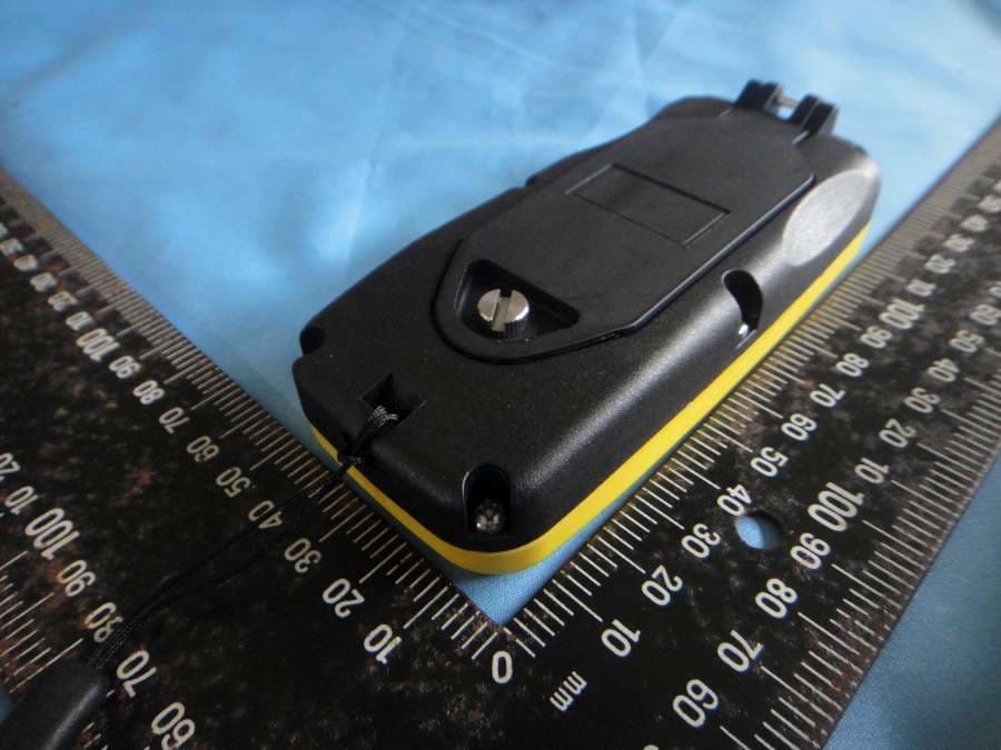
Click to zoom
Application Details
- Equipment Class
- DXX - Part 15 Low Power Communication Device Transmitter
- Date of Grant
- Feb 10, 2013
- Application Purpose
- Original Equipment
- Date of Application
- Feb 10, 2013
- Equipment Note
- Industrial Radio Remote Controller
- Frequency Range
- 904.03300000 - 925.87300000
- Company
- Gain Electronic Co Ltd
- Country
- Taiwan
Documents & Files
Document Text
Text extracted from the exhibit documents filed with the FCC. Open a document above to read the original.
Users Manual
Industrial Radio Remote Controller SAGA1-T Series User Manual Gain Electronic Co., Ltd. www.sagaradio.com.tw S S A A F F E E T T Y Y / / R R E E L L I I A A B B I I L L I I T T Y Y / / U U S S E E R R - - F F R R I I E E N N D D L L Y Y Warning and Caution The following symbols may be found on the product or throughout the documentation. Symbol Description Refer to Manual Refer the user manual for additional information when product marked with this sign. Dangerous Voltage Indicates presence of hazardous voltage. Unsafe practice could result in severe personal injury. Warning Denotes a hazard. Included text gives proper procedures. Failure to follow instructions could result in severe personal injury and/or property damage. Caution Denotes a hazard. Included text gives proper procedures.Failure to follow instructions could result in minor personal injury and/or properly damage. FCC Compliance Statement This device complies with Part 15 of the FCC Rules. Operation is subject to the following two conditions: (1) This device may not cause harmful interference, and (2) This device must accept any interference received, including interference that may cause undesired operation. (3) Changes or modifications not expressly approved by the party responsible for compliance could void the user's authority to operate the equipment. Industry Canada Notice Operation is subject to the following two conditions: (1) this device may not cause interference and (2) this device must accept any interference, including interference that may cause undesired operation of the device. Industry Canada Caution This device complies with Industry Canada licence-exempt RSS standard(s). Operation is subject to the following two conditions: (1) this device may not cause interference, and (2) this device must accept any interference, including interference that may cause undesired operation of the device. Le présent appareil est conforme aux CNR d'IndustrieCanadaapplicables aux appareils radio exempts de licence. L'exploitation est autorisée aux deux conditions suivantes : (1) l'appareil ne doit pas produire de brouillage, et (2) l'utilisateur de l'appareil doit accepter tout brouillage radioélectrique subi, même si le brouillage est susceptible d'en compromettre le fonctionnement. Limited Warranty Warranty Gain Electronic Co., Ltd. guarantees that this equipment meets its published specifications at the time of shipment from the factory. This equipment will perform as described if installed properly. However, Gain cannot guarantee that operation in SAGA product is absolutely error-free, or without interruption. Warranty Period This equipment is warranted against defects in materials and workmanship for a period of one year from the date of shipment. During the warranty period, Gain is responsible for necessary repairs as long as the product can be proved to be defective. For warranty service or repair, this equipment must be returned to the service facility designated by Gain. Customer is responsible for shipping charges to Gain, while Gain will bear return shipping charges. Excluded Items This warranty does not include consumable parts such as batteries, fuses, buttons and relays. Also this warranty does not cover failure or damage resulting from misuse, accident, unauthorized modification, unsuitable operating environment, natural disasters, improper software setting or improper maintenance. Limitation of liability and remedy If your SAGA product fails to work as warranted above, Gain's maximum liability under this limited warranty is expressly limited to the lesser of the price you have paid for the product. Gain disclaims any liability as a result of any direct/indirect, special, incidental or consequential damages. Remarks No other warranty is expressed or implied, except for the above mentioned. Important Information before You Start Important 1. Read this manual carefully before operating and installation. 2. Due to the complex nature of equipment, it is necessary to read the entire manual before installation. 1. 2. 3. 4. 5. 6. 7. 8. 9. 10. Never allow any unauthorized personnel to dismantle equipment as this may cause the equipment damage. The equipment has been stringently tested for quality assurance before delivery from factory. However, it must not be used in extremely dangerous situations, or where damage may result. After operation, switch off crane main power as well as receiver unit and remove rotary key from transmitter unit. The transmitter should keep in a safe place when not in use to avoid any unintentionally operation. The crane should be equipped with main power relay, limit switch and other safety devices required. Do not use this device during electrical storm or where there are conditions of high electrical interference. Always check transmitter battery and receiver input power condition before operation. The installation and maintenance service is allowed only when the crane and receiver power are off to avoid electrical shock. The contents of the manual may be amended by the manufacturer without notice. The specification and function is subjected to change without notice by manufacturer. Precautions 1. 2. 3. 4. 5. 6. 7. 1. 2. 3. Press EMS button and switch off main power of crane and receiver after operation. The following situations may cause receiver response delay and stop operation immediately when situation occurs. (a) Beyond operating range (b) During severe radio interference Remove transmitter batteries when not in use for long period of time. To extend product life, please follow the standard operating procedure and maintain system regularly. Check EMS button and other system main functions before operation. Press EMS button during system failure or any abnormal conditions occur. The operator must be familiar with emergency procedures before operate the system. Emergency Procedures In case of emergency, please follow the procedure below: Press EMS button and stop operation. Switch off…
Text truncated - open the document above for the full version.
Cover Letter(s)
Date: February 5, 2013 Product: Industrial Radio Remote Conrtoller Model : SAGA1-T8 FCC ID: NCT12CT8 IC: 2802A-12CT8 Model Difference To whom it may concern, Due to the business consideration, we hereby declare that our product of Industrial Radio Remote Controller , model: SAGA1-T8 / SAGA1-T6 / SAGA1-T4have as following difference Model Description: To add a series model for business necessary. (Single-speed push-button: SKQ1ADA010) Model Different Item SAGA1-T4 SAGA1-T6 SAGA1-T8 Brand SAGA SAGA GAIN Transmitter PCB Same Same Same Transmitter Power Supply Same Same Same Transmitter RF Circuit Design Same Same Same Transmitter Key Numbers & Spec. Four units of single-speed push-button Six units of single-speed push-button Eight units of single-speed push-button The Products between these models are all the same except for Transmitter Key number. ISO 9001 Any questions regarding this declaration, please don’t hesitate to contact us. Sincerely yours,
External Photos
Compliance Certification Services Inc. Report No.:T121222N02-RP1 Page A1 / 6 External Photo (SAGA1-T8) Compliance Certification Services Inc. Report No.:T121222N02-RP1 Page A2 / 6 Compliance Certification Services Inc. Report No.:T121222N02-RP1 Page A6 / 6 Series Photo (SAGA1-T6) Series Photo (SAGA1-T4)
ID Label/Location Info
g Company : Gain Electronic Co., Ltd. Model: SAGA1-T8 Product : Industrial Radio Remote Controller Label Here Model No: SAGA1-T8 FCC ID: NCT12CT8 This device complies with part 15 of the FCC Rules. Operation is subject to the following two conditions: (1) this device may not cause harmful interference and (2) this device must accept any interference received, including interference that may cause undesired operation. REMOTE CONTROL Model No: SAGA1-T8 FCC ID:NCT12CT8 This device complies with part 15 of the FCC Rules. Operation is subject to the following two conditions: [1] this device may not cause harmful interference and [2] this device must accept any interference received, including interference that may cause undesired operation. S/N: Made in Taiwan
Internal Photos
Compliance Certification Services Inc. Report No.:T121222N02-RP1 Page A3 / 6 Internal Photo (SAGA1-T8) Compliance Certification Services Inc. Report No.:T121222N02-RP1 Page A4 / 6 Antenna Compliance Certification Services Inc. Report No.:T121222N02-RP1 Page A5 / 6
Parts List/Tune Up Info
ISO 9001 Model No.: SAGA1-T8 TYPE: Planar inverted-F antenna (PIFA) FREQUENCY: 904MHz ~ 926.1MHz GAIN(dBi) ≦0 V.S.W.R. ≦1.2 POLARIZATION Elliptical Polarization Power Capability ≦0.3W INPUT CONNECTOR on Pcb Radiation Element Material Copper Dimension(mm) See Figure1 Impedance 50Ω Weight <1g Figure1 44mm
Test Report
Compliance Certification Services Inc. FCC ID: NCT12CT8 Report No.: T121222N02-RP1 Note: This report shall not be reproduced except in full, without the written approval of Compliance Certification Services Inc. This document may be altered or revised by Compliance Certification Services Inc. personnel only, and shall be noted in the revision section of the document. Page 1/ 32 FCC 47 CFR PART 15 SUBPART C ANSI C63.4: 2003 TEST REPORT For Industrial Radio Remote Controller MODEL: SAGA1-T8 DATA APPLIES TO: SAGA1-T6; SAGA1-T4 BRAND: SAGA Issued to GAIN ELECTRONIC CO., LTD 4F-1, NO.288-5, HSIN YA RD, CHIEN CHEN ZONE (806), KAOHSIUNG, TAIWAN, ROC Issued by Compliance Certification Services Inc. Tainan Lab. No.8,Jiucengling, Xinhua Dist., Tainan City 712, Taiwan (R.O.C.) TEL: (06) 580-2201 FAX: (06) 580-2202 Issued Date: January 29, 2013 Compliance Certification Services Inc. FCC ID: NCT12CT8 Report No.: T121222N02-RP1 Page 2 / 41 REVISION HISTORY Rev. Issue Date Revisions Effect Page Revised By 00 January 29, 2013 Initial Issue ALL Eva Lin Compliance Certification Services Inc. FCC ID: NCT12CT8 Report No.: T121222N02-RP1 Page 3 / 41 TABLE OF CONTENTS 1. TEST RESULT CERTIFICATION .........................................................................4 2. EUT DESCRIPTION..............................................................................................5 3. TEST METHODOLOGY........................................................................................7 3.1 EUT CONFIGURATION ...................................................................................7 3.2 EUT EXERCISE ...............................................................................................7 3.3 GENERAL TEST PROCEDURES ....................................................................7 3.4 FCC PART 15.205 RESTRICTED BANDS OF OPERATIONS ........................8 3.5 DESCRIPTION OF TEST MODES...................................................................8 4. INSTRUMENT CALIBRATION .............................................................................9 4.1 MEASURING INSTRUMENT CALIBRATION ..................................................9 4.2 MEASUREMENT EQUIPMENT USED ............................................................9 4.3 MEASUREMENT UNCERTAINTY .................................................................10 5. FACILITIES AND ACCREDITATIONS ...............................................................11 5.1 FACILITIES ....................................................................................................11 5.2 EQUIPMENT ..................................................................................................11 5.3 LABORATORY ACCREDITATIONS LISTING ...............................................11 5.4 TABLE OF ACCREDITATIONS AND LISTINGS............................................12 6. SETUP OF EQUIPMENT UNDER TEST ............................................................13 6.1 SETUP CONFIGURATION OF EUT ..............................................................13 6.2 SUPPORT EQUIPMENT................................................................................13 6.3 CENTER FREQUENCY CHECK....................................................................14 7. FCC PART 15.249 REQUIREMENTS ................................................................16 7.1 20 DB BANDWIDTH.......................................................................................16 7.2 BAND EDGES MEASUREMENT ...................................................................19 7.3 DUTY CYCLE.................................................................................................20 7.4 SPURIOUS EMISSION..................................................................................22 7.5 POWERLINE CONDUCTED EMISSIONS .....................................................38 APPENDIX I - PHOTOGRAPHS OF TEST SETUP .................................................39 APPENDIX II - PHOTOGRAPHS OF EUT .............................................................. A1 Compliance Certification Services Inc. FCC ID: NCT12CT8 Report No.: T121222N02-RP1 Page 4 / 41 1. TEST RESULT CERTIFICATION Product: Industrial Radio Remote Controller Model: SAGA1-T8 Data Applies To: SAGA1-T6; SAGA1-T4 Brand Name: SAGA Applicant: GAIN ELECTRONIC CO., LTD 4F-1, NO.288-5, HSIN YA RD, CHIEN CHEN ZONE (806), KAOHSIUNG, TAIWAN, ROC Manufacturer: GAIN ELECTRONIC CO., LTD 4F-1, NO.288-5, HSIN YA RD, CHIEN CHEN ZONE (806), KAOHSIUNG, TAIWAN, ROC Tested: January 4, 2013 – January 22, 2013 APPLICABLE STANDARDS STANDARD TEST RESULT FCC 47 CFR Part 15 Subpart C ANSI C63.4 : 2003 No non-compliance noted We hereby certify that: The above equipment was tested by Compliance Certification Services Inc. The test data, data evaluation, test procedures, and equipment configurations shown in this report were made in accordance with the procedures given in ANSI C63.4: 2003 and the energy emitted by the sample EUT tested as described in this report is in compliance with the requirements emission limits of FCC Rules Part 15.107, 15.109,15.207, 15.209 and 15.249. The test results of this report relate only to the tested sample identified in this report. Approved by: Reviewed by: Jeter Wu Assistant Manager Eric Huang Assistant Section Manager Compliance Certification Services Inc. FCC ID: NCT12CT8 Report No.: T121222N02-RP1 Page 5 / 41 2. EUT DESCRIPTION Product Industrial Radio Remote Controller Model Number SAGA1-T8 Data Applies To SAGA1-T6; SAGA1-T4 Brand Name SAGA Received Date December 22, 2012 Frequency Range 904 MHz to 926.1 MHz Transmit Peak Power 93.38 dBμV/m Data Rate 4.8 kbps Number of Channels 160 Channels Type of Modulation FSK Power Supply 3Vdc Antenna Type PIFA antenna Gain: 0 dBi≦ Temperature Range -15°C ~ +60°C Remark: 1. Client consigns only one model sample to test (Model Number: SAGA1-T8). Therefore, the testing Lab. just guarantees the unit, which has been tested. 2. This submitta…
Text truncated - open the document above for the full version.
Test Setup Photos
Compliance Certification Services Inc. FCC ID: NCT12CT8 Report No.: T121222N02-RP1 Page 39 / 41 APPENDIX I - PHOTOGRAPHS OF TEST SETUP RADIATED RF EMISSION MEASUREMENT SETUP Compliance Certification Services Inc. FCC ID: NCT12CT8 Report No.: T121222N02-RP1 Page 40 / 41 Compliance Certification Services Inc. FCC ID: NCT12CT8 Report No.: T121222N02-RP1 Page 41 / 41 RADIATED EMISSION SETUP
Contact Information
Applicant
Mr.Danny Lin(Marketing Director)
Technical Contact
Compliance Certification Services Inc.Daphne Liang
[email protected](06) 580-2201
No.8,Jiucengling, Xinhua Dist. · Tainan City · Taiwan
Non-Technical Contact
Compliance Certification Services Inc.Daphne Liang
[email protected](06) 580-2201
Test Firm
Compliance Certification Services Inc.Tommy WU
Technical Specifications
| # | Rule Parts | Frequency Range | Power Output |
|---|---|---|---|
| 1 | 15C | 904.033 MHz - 925.873 MHz | - |
Other Applications from Gain Electronic Co Ltd
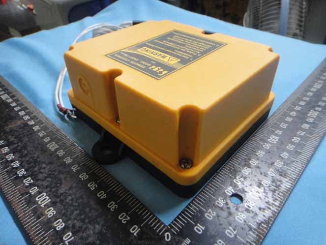
NCT137V6R
Aug 25, 2013Industrial Radio Remote Controller
Equipment Class
DXX - Part 15 Low Power Communication Device Transmitter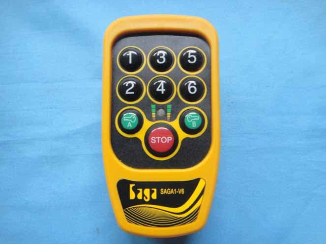
NCT137V6T
Aug 25, 2013Industrial Radio Remote Controller
Equipment Class
DXX - Part 15 Low Power Communication Device Transmitter
NCT12CP40
Feb 10, 2013Industrial Radio Remote Controller
Equipment Class
DXX - Part 15 Low Power Communication Device Transmitter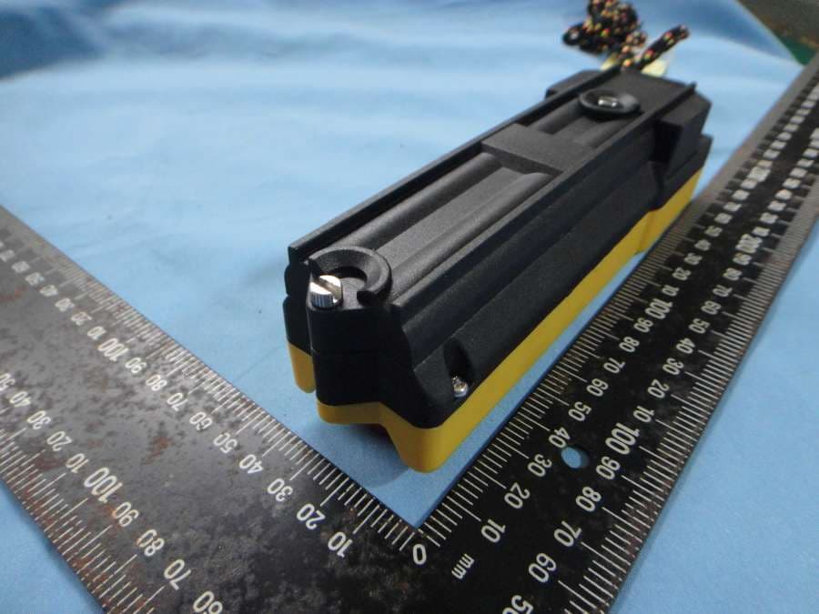
NCT12BP10
Dec 19, 2012Industrial Radio Remote Controller
Equipment Class
DXX - Part 15 Low Power Communication Device Transmitter
NCT12BP12
Dec 19, 2012Industrial Radio Remote Controller
Equipment Class
DXX - Part 15 Low Power Communication Device Transmitter